SlideShare a Scribd company logo
1 of 2
Download to read offline
CAMLift hydraulic pumping units.
14-64 30-120 30-144 40-192
CAMLIFT Linear Lifting System
CAMLIFT 14-64 CAMLIFT 30-120 CAMLIFT 30-144 CAMLIFT
Cameron’s CAMLIFT Linear Lifting Systems
As a compact, lighter weight alternative to the traditional
beam pumping unit, Cameron offers a series of CAMLIFT™
linear lifting systems to operators interested in:
• Minimizing installation costs
• Reducing operating costs
• Improving production efficiency
• Eliminating ground site preparation and installation time
• The efficient design of these CAMLIFTs uses le
the footprint of a conventional pumping unit
• Maximizing production efficiency as a result o
to quickly complete adjustments (such as stro
stroke length, placing the well on/off tap)
• Retaining operator control as the need for sp
crews and equipment to make system adjustm
eliminated
CAMLIFT Linear Lifting System
CAMLIFT 14-64 CAMLIFT 30-120 CAMLIFT 30-144 CAMLIFT 40
Cameron’s CAMLIFT Linear Lifting Systems
As a compact, lighter weight alternative to the traditional
beam pumping unit, Cameron offers a series of CAMLIFT™
linear lifting systems to operators interested in:
• Minimizing installation costs
• Reducing operating costs
• Improving production efficiency
• Eliminating ground site preparation and installation time
• The efficient design of these CAMLIFTs uses less t
the footprint of a conventional pumping unit
• Maximizing production efficiency as a result of th
to quickly complete adjustments (such as stroke s
stroke length, placing the well on/off tap)
• Retaining operator control as the need for specia
crews and equipment to make system adjustmen
eliminated
CAMLIFT Linear Lifting System
CAMLIFT 14-64 CAMLIFT 30-120 CAMLIFT 30-144 CAMLIFT 40-192
Cameron’s CAMLIFT Linear Lifting Systems
As a compact, lighter weight alternative to the traditional
beam pumping unit, Cameron offers a series of CAMLIFT™
linear lifting systems to operators interested in:
• Minimizing installation costs
• Reducing operating costs
• Improving production efficiency
• Eliminating ground site preparation and installation time
• The efficient design of these CAMLIFTs uses less than 1/10
the footprint of a conventional pumping unit
• Maximizing production efficiency as a result of the ability
to quickly complete adjustments (such as stroke speed,
stroke length, placing the well on/off tap)
• Retaining operator control as the need for specialized
crews and equipment to make system adjustments is
eliminated
The CAMLift* hydraulic pumping unit is a compact, lighter weight alternative to the traditional beam
pumping unit. Schlumberger offers a series of CAMLift units to operators interested in reducing
operating costs, maximizing efficiency, and reducing wellsite footprint.
APPLICATIONS
■■ Conventional oil
■■ Gas well dewatering
■■ Heavy oil
■■ Horizontal wells
■■ Steam-assisted gravity drainage (SAGD)
■■ Shale gas deliquification
■■ Shale oil
BENEFITS
■■ Minimizes installation costs associated
with transportation, ground preparation,
jack alignment, and installation service
■■ Reduces operating costs by increasing
system run life and reducing well service
and equipment service frequencies
■■ Improves production uptime through faster
installation, operator adjustments, and
local service
■■ Reduces wellsite footprint by requiring
only 1/10 the footprint of most beam
pumping units at the wellhead
■■ Retains operator control by eliminating the
need for specialized crews and equipment
to make system adjustments
■■ Maximizes production efficiency through
quick system adjustments (such as stroke
speed, stroke length, placing the well on/
off tap) and independent up and down
stroke speeds
■■ Reduces HSE risk by eliminating large
rotating equipment and guide wires
FEATURES
■■ Direct mount to wellhead
■■ Easy stroke and speed adjustment
■■ Independent up and down
stroke equipment
CAMLift
Hydraulic pumping units
­*Mark of Schlumberger
Copyright © 2016 Schlumberger. All rights reserved. 16-AL-139851
CAMLift
slb.com/rodlift
CAMLift Hydraulic Pumping Unit Specifications
14-64 30-120 CamLift 30-144 CamLift 40-192
Applications Shallow gas/coalbed
methane dewatering
Light or medium crude
Light to heavy crude
Dewatering natural gas and
coalbed methane
Light to heavy crude
Dewatering natural gas and
coalbed methane
Horizontal completions
Light to heavy crude
High volume
Depths to 13,000 ft
Horizontal completions
Vertical, slant, or deviated well application
Lift capacity, lbm 14,000 30,000 30,000 40,000
Max. stroke length, in 64 120 144 192
Max. speed†, strokes per minute 8 5.5 5.5 6.5
Min. speed†, strokes per minute 0.5 0.5 0.5 1.5
Jack dimensions (L×W×H) 20” × 18”× 7’5” 49”× 30”× 12’4” 49”× 30”× 14’4” 51”× 31”× 19’9”
Jack shipping weight, lbm 675 1100 1250 2250
Skid dimenstions (L×W×H), 9’7”× 3’10”× 8’ 9’7”× 3’10”× 8’ 9’7”× 3’10”× 8’ 13’× 8’× 7’3”
Skid shipping weight, lbm 3,300 3,300 3,300 12,000
Installation time, h <3 <3 <3 <6
Replaces 114s
80s
57s
456s
320s
228s
456s
320s
228s
PCPs
912s
640s
456s
ESPs
PCPs
† Maximum speed is dependent on many variables. Please review application with us for accurate production range.
Conventional Pumping Units vs. CAMLift Hydraulic Pumping Units
Conventional Units CAMLift Hydraulic Pumping Unit
Ships in 1 to 3 trailer loads,
depending on size
Ship up to four units on one trailer
Site preparation with gravel,
concrete slab, and piles
No mandatory site preparation, bolts directly
to the wellhead; skid fully contained
Installs in 2–5 days Installs in  6 hours
Footprint of 10 ft × 10 ft or larger Minimal footprint next to well
Installation and all adjustments
require special crew, cranes, pickers
Simple installation process, operators can
make speed and stroke length adjustments
Requires VFD for production
optimization
Independent up and down stroke speeds to
allow for optimization
Takes hours to treat gas lock—
shutting down production
Taps well in seconds to clear gas lock with
no production downtime
Requires crane to remove pump
that is on tap, leading to premature
pump failure
Operator can take pump off tap with no
production downtime
All limitations for oil production are
the same for dewatering
All benefits on oil production are the same
for dewatering
Key Features
320-256-120 30-120
Lift capacity, lbm 25,600 30,000
Stroke length, in 90, 105, 120 40 to 120
Dimensions (L × W × H) 33.3 ft × 7.6 ft × 25 ft 49”× 30”× 12’4”
Total weight, lbm 32,550 4,350
Footprint, ft 22 × 7 N/A (bolts to wellhead)
Drawn to scale.

More Related Content

What's hot

Best practices day 2 afternoon
Best practices day 2 afternoonBest practices day 2 afternoon
Best practices day 2 afternoonAhmed Radwan
 
Plunger Pumps Pulsation Dampener Designs
Plunger Pumps Pulsation Dampener DesignsPlunger Pumps Pulsation Dampener Designs
Plunger Pumps Pulsation Dampener DesignsAbdulrahman Alkhowaiter
 
MANUALS FOR FLUID MECHANICS LAB.pdf
MANUALS FOR FLUID MECHANICS LAB.pdfMANUALS FOR FLUID MECHANICS LAB.pdf
MANUALS FOR FLUID MECHANICS LAB.pdfamgothusandeep
 
Best practices day one new morning
Best practices day one new morningBest practices day one new morning
Best practices day one new morningAhmed Radwan
 
Positive displacement pumps
Positive displacement pumpsPositive displacement pumps
Positive displacement pumpsKarnav Rana
 
رضا مصطفوی طباطبایی, hydraulic workover and snubbing solutions
رضا مصطفوی طباطبایی, hydraulic workover and snubbing solutionsرضا مصطفوی طباطبایی, hydraulic workover and snubbing solutions
رضا مصطفوی طباطبایی, hydraulic workover and snubbing solutionsReza Mostafavi Tabatabaei
 
Well Testing Surface safety Valve (SSV), Well Test Valves - WOM Group
Well Testing Surface safety Valve (SSV), Well Test Valves - WOM GroupWell Testing Surface safety Valve (SSV), Well Test Valves - WOM Group
Well Testing Surface safety Valve (SSV), Well Test Valves - WOM Groupwomgroup
 
1 b. pneumatic components
1 b. pneumatic components1 b. pneumatic components
1 b. pneumatic componentsDr.R. SELVAM
 

What's hot (20)

Best practices day 2 afternoon
Best practices day 2 afternoonBest practices day 2 afternoon
Best practices day 2 afternoon
 
Centrifugal pumps
Centrifugal pumpsCentrifugal pumps
Centrifugal pumps
 
Plunger Pumps Pulsation Dampener Designs
Plunger Pumps Pulsation Dampener DesignsPlunger Pumps Pulsation Dampener Designs
Plunger Pumps Pulsation Dampener Designs
 
MANUALS FOR FLUID MECHANICS LAB.pdf
MANUALS FOR FLUID MECHANICS LAB.pdfMANUALS FOR FLUID MECHANICS LAB.pdf
MANUALS FOR FLUID MECHANICS LAB.pdf
 
Compressor
CompressorCompressor
Compressor
 
Best practices day one new morning
Best practices day one new morningBest practices day one new morning
Best practices day one new morning
 
Positive displacement pumps
Positive displacement pumpsPositive displacement pumps
Positive displacement pumps
 
رضا مصطفوی طباطبایی, hydraulic workover and snubbing solutions
رضا مصطفوی طباطبایی, hydraulic workover and snubbing solutionsرضا مصطفوی طباطبایی, hydraulic workover and snubbing solutions
رضا مصطفوی طباطبایی, hydraulic workover and snubbing solutions
 
Well Testing Surface safety Valve (SSV), Well Test Valves - WOM Group
Well Testing Surface safety Valve (SSV), Well Test Valves - WOM GroupWell Testing Surface safety Valve (SSV), Well Test Valves - WOM Group
Well Testing Surface safety Valve (SSV), Well Test Valves - WOM Group
 
How does a pump stroke counter work
How does a pump stroke counter workHow does a pump stroke counter work
How does a pump stroke counter work
 
Shuttle valve
Shuttle valveShuttle valve
Shuttle valve
 
Maxing Energy Jar
Maxing Energy JarMaxing Energy Jar
Maxing Energy Jar
 
Discharge Dampeners for Pulsation Control
Discharge Dampeners for Pulsation ControlDischarge Dampeners for Pulsation Control
Discharge Dampeners for Pulsation Control
 
Hidraulik
HidraulikHidraulik
Hidraulik
 
Modul 8 hydraulic
Modul 8 hydraulicModul 8 hydraulic
Modul 8 hydraulic
 
blow out preventer system
blow out preventer systemblow out preventer system
blow out preventer system
 
Basic Coiled Tubing Ops.pptx
Basic Coiled Tubing Ops.pptxBasic Coiled Tubing Ops.pptx
Basic Coiled Tubing Ops.pptx
 
1 b. pneumatic components
1 b. pneumatic components1 b. pneumatic components
1 b. pneumatic components
 
Casing_Design(1).ppt
Casing_Design(1).pptCasing_Design(1).ppt
Casing_Design(1).ppt
 
Servo Valves
Servo Valves Servo Valves
Servo Valves
 

Similar to camlift-hydraulic-pumping-unit-ps

Centrifugal compressors-brochure
Centrifugal compressors-brochureCentrifugal compressors-brochure
Centrifugal compressors-brochureR.V Koushik
 
Hydro_Jetting_Machine_Catalogue.PDF
Hydro_Jetting_Machine_Catalogue.PDFHydro_Jetting_Machine_Catalogue.PDF
Hydro_Jetting_Machine_Catalogue.PDFPressure Jet
 
PressureJet - Manufacturer Of High Pressure Hydro Test Pump, Hydro Jetting Ma...
PressureJet - Manufacturer Of High Pressure Hydro Test Pump, Hydro Jetting Ma...PressureJet - Manufacturer Of High Pressure Hydro Test Pump, Hydro Jetting Ma...
PressureJet - Manufacturer Of High Pressure Hydro Test Pump, Hydro Jetting Ma...sewerjettingpumps
 
Global Perspective on the Future of Subsea Technology
Global Perspective on the Future of Subsea TechnologyGlobal Perspective on the Future of Subsea Technology
Global Perspective on the Future of Subsea TechnologyConference_Presentations
 
New Wave Energy Services Ltd. Presentation 2016 US
New Wave Energy Services Ltd. Presentation 2016 USNew Wave Energy Services Ltd. Presentation 2016 US
New Wave Energy Services Ltd. Presentation 2016 USKristopher Vardell
 
A&W series Presentation.ppt
A&W series Presentation.pptA&W series Presentation.ppt
A&W series Presentation.pptJayeshChand2
 
Portable Compressor Manufacturer
Portable Compressor ManufacturerPortable Compressor Manufacturer
Portable Compressor Manufacturerrotairspa
 
Authorised Pumpset Original Equipment Menufacturer
Authorised Pumpset Original Equipment MenufacturerAuthorised Pumpset Original Equipment Menufacturer
Authorised Pumpset Original Equipment MenufacturerVijayEngineeringandM1
 
Masters Distributors of KBL Process Pumps.
Masters Distributors of KBL Process Pumps.Masters Distributors of KBL Process Pumps.
Masters Distributors of KBL Process Pumps.VijayEngineeringandM1
 
Hydro_Jetting_Machine_Catalogue.pptx
Hydro_Jetting_Machine_Catalogue.pptxHydro_Jetting_Machine_Catalogue.pptx
Hydro_Jetting_Machine_Catalogue.pptxsewerjettingpumps
 
Cylinder-and-synchronous-lifting-system.pdf
Cylinder-and-synchronous-lifting-system.pdfCylinder-and-synchronous-lifting-system.pdf
Cylinder-and-synchronous-lifting-system.pdffurqankhatri5
 
Cylinder and synchronous lifting system
Cylinder and synchronous lifting systemCylinder and synchronous lifting system
Cylinder and synchronous lifting systemtorcstark
 
Escavadeira hidraulica cat 390 dl
Escavadeira hidraulica cat 390 dlEscavadeira hidraulica cat 390 dl
Escavadeira hidraulica cat 390 dl85283081
 

Similar to camlift-hydraulic-pumping-unit-ps (20)

Centrifugal compressors-brochure
Centrifugal compressors-brochureCentrifugal compressors-brochure
Centrifugal compressors-brochure
 
Hydro_Jetting_Machine_Catalogue.PDF
Hydro_Jetting_Machine_Catalogue.PDFHydro_Jetting_Machine_Catalogue.PDF
Hydro_Jetting_Machine_Catalogue.PDF
 
PressureJet - Manufacturer Of High Pressure Hydro Test Pump, Hydro Jetting Ma...
PressureJet - Manufacturer Of High Pressure Hydro Test Pump, Hydro Jetting Ma...PressureJet - Manufacturer Of High Pressure Hydro Test Pump, Hydro Jetting Ma...
PressureJet - Manufacturer Of High Pressure Hydro Test Pump, Hydro Jetting Ma...
 
Brochure sinamics-siemens
Brochure sinamics-siemensBrochure sinamics-siemens
Brochure sinamics-siemens
 
Global Perspective on the Future of Subsea Technology
Global Perspective on the Future of Subsea TechnologyGlobal Perspective on the Future of Subsea Technology
Global Perspective on the Future of Subsea Technology
 
INTRODUCTION TO VEMC.pptx
INTRODUCTION TO VEMC.pptxINTRODUCTION TO VEMC.pptx
INTRODUCTION TO VEMC.pptx
 
aci.online
aci.onlineaci.online
aci.online
 
390 d
390 d390 d
390 d
 
New Wave Energy Services Ltd. Presentation 2016 US
New Wave Energy Services Ltd. Presentation 2016 USNew Wave Energy Services Ltd. Presentation 2016 US
New Wave Energy Services Ltd. Presentation 2016 US
 
APOEM PLANT LAUNCH
APOEM PLANT LAUNCHAPOEM PLANT LAUNCH
APOEM PLANT LAUNCH
 
A&W series Presentation.ppt
A&W series Presentation.pptA&W series Presentation.ppt
A&W series Presentation.ppt
 
Portable Compressor Manufacturer
Portable Compressor ManufacturerPortable Compressor Manufacturer
Portable Compressor Manufacturer
 
Authorised Pumpset Original Equipment Menufacturer
Authorised Pumpset Original Equipment MenufacturerAuthorised Pumpset Original Equipment Menufacturer
Authorised Pumpset Original Equipment Menufacturer
 
Masters Distributors of KBL Process Pumps.
Masters Distributors of KBL Process Pumps.Masters Distributors of KBL Process Pumps.
Masters Distributors of KBL Process Pumps.
 
Hydro_Jetting_Machine_Catalogue.pptx
Hydro_Jetting_Machine_Catalogue.pptxHydro_Jetting_Machine_Catalogue.pptx
Hydro_Jetting_Machine_Catalogue.pptx
 
Qsk95 genset overview
Qsk95 genset overviewQsk95 genset overview
Qsk95 genset overview
 
Amtech-Variable-Frequency-drive-Motor-Control.pdf
Amtech-Variable-Frequency-drive-Motor-Control.pdfAmtech-Variable-Frequency-drive-Motor-Control.pdf
Amtech-Variable-Frequency-drive-Motor-Control.pdf
 
Cylinder-and-synchronous-lifting-system.pdf
Cylinder-and-synchronous-lifting-system.pdfCylinder-and-synchronous-lifting-system.pdf
Cylinder-and-synchronous-lifting-system.pdf
 
Cylinder and synchronous lifting system
Cylinder and synchronous lifting systemCylinder and synchronous lifting system
Cylinder and synchronous lifting system
 
Escavadeira hidraulica cat 390 dl
Escavadeira hidraulica cat 390 dlEscavadeira hidraulica cat 390 dl
Escavadeira hidraulica cat 390 dl
 

camlift-hydraulic-pumping-unit-ps

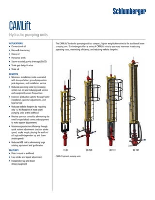
  • 1. CAMLift hydraulic pumping units. 14-64 30-120 30-144 40-192 CAMLIFT Linear Lifting System CAMLIFT 14-64 CAMLIFT 30-120 CAMLIFT 30-144 CAMLIFT Cameron’s CAMLIFT Linear Lifting Systems As a compact, lighter weight alternative to the traditional beam pumping unit, Cameron offers a series of CAMLIFT™ linear lifting systems to operators interested in: • Minimizing installation costs • Reducing operating costs • Improving production efficiency • Eliminating ground site preparation and installation time • The efficient design of these CAMLIFTs uses le the footprint of a conventional pumping unit • Maximizing production efficiency as a result o to quickly complete adjustments (such as stro stroke length, placing the well on/off tap) • Retaining operator control as the need for sp crews and equipment to make system adjustm eliminated CAMLIFT Linear Lifting System CAMLIFT 14-64 CAMLIFT 30-120 CAMLIFT 30-144 CAMLIFT 40 Cameron’s CAMLIFT Linear Lifting Systems As a compact, lighter weight alternative to the traditional beam pumping unit, Cameron offers a series of CAMLIFT™ linear lifting systems to operators interested in: • Minimizing installation costs • Reducing operating costs • Improving production efficiency • Eliminating ground site preparation and installation time • The efficient design of these CAMLIFTs uses less t the footprint of a conventional pumping unit • Maximizing production efficiency as a result of th to quickly complete adjustments (such as stroke s stroke length, placing the well on/off tap) • Retaining operator control as the need for specia crews and equipment to make system adjustmen eliminated CAMLIFT Linear Lifting System CAMLIFT 14-64 CAMLIFT 30-120 CAMLIFT 30-144 CAMLIFT 40-192 Cameron’s CAMLIFT Linear Lifting Systems As a compact, lighter weight alternative to the traditional beam pumping unit, Cameron offers a series of CAMLIFT™ linear lifting systems to operators interested in: • Minimizing installation costs • Reducing operating costs • Improving production efficiency • Eliminating ground site preparation and installation time • The efficient design of these CAMLIFTs uses less than 1/10 the footprint of a conventional pumping unit • Maximizing production efficiency as a result of the ability to quickly complete adjustments (such as stroke speed, stroke length, placing the well on/off tap) • Retaining operator control as the need for specialized crews and equipment to make system adjustments is eliminated CAMLIFT Linear Lifting System CAMLIFT 14-64 CAMLIFT 30-120 CAMLIFT 30-144 CAMLIFT 40-192 Cameron’s CAMLIFT Linear Lifting Systems As a compact, lighter weight alternative to the traditional beam pumping unit, Cameron offers a series of CAMLIFT™ linear lifting systems to operators interested in: • Minimizing installation costs • Reducing operating costs • Improving production efficiency • Eliminating ground site preparation and installation time • The efficient design of these CAMLIFTs uses less than 1/10 the footprint of a conventional pumping unit • Maximizing production efficiency as a result of the ability to quickly complete adjustments (such as stroke speed, stroke length, placing the well on/off tap) • Retaining operator control as the need for specialized crews and equipment to make system adjustments is eliminated The CAMLift* hydraulic pumping unit is a compact, lighter weight alternative to the traditional beam pumping unit. Schlumberger offers a series of CAMLift units to operators interested in reducing operating costs, maximizing efficiency, and reducing wellsite footprint. APPLICATIONS ■■ Conventional oil ■■ Gas well dewatering ■■ Heavy oil ■■ Horizontal wells ■■ Steam-assisted gravity drainage (SAGD) ■■ Shale gas deliquification ■■ Shale oil BENEFITS ■■ Minimizes installation costs associated with transportation, ground preparation, jack alignment, and installation service ■■ Reduces operating costs by increasing system run life and reducing well service and equipment service frequencies ■■ Improves production uptime through faster installation, operator adjustments, and local service ■■ Reduces wellsite footprint by requiring only 1/10 the footprint of most beam pumping units at the wellhead ■■ Retains operator control by eliminating the need for specialized crews and equipment to make system adjustments ■■ Maximizes production efficiency through quick system adjustments (such as stroke speed, stroke length, placing the well on/ off tap) and independent up and down stroke speeds ■■ Reduces HSE risk by eliminating large rotating equipment and guide wires FEATURES ■■ Direct mount to wellhead ■■ Easy stroke and speed adjustment ■■ Independent up and down stroke equipment CAMLift Hydraulic pumping units
  • 2. ­*Mark of Schlumberger Copyright © 2016 Schlumberger. All rights reserved. 16-AL-139851 CAMLift slb.com/rodlift CAMLift Hydraulic Pumping Unit Specifications 14-64 30-120 CamLift 30-144 CamLift 40-192 Applications Shallow gas/coalbed methane dewatering Light or medium crude Light to heavy crude Dewatering natural gas and coalbed methane Light to heavy crude Dewatering natural gas and coalbed methane Horizontal completions Light to heavy crude High volume Depths to 13,000 ft Horizontal completions Vertical, slant, or deviated well application Lift capacity, lbm 14,000 30,000 30,000 40,000 Max. stroke length, in 64 120 144 192 Max. speed†, strokes per minute 8 5.5 5.5 6.5 Min. speed†, strokes per minute 0.5 0.5 0.5 1.5 Jack dimensions (L×W×H) 20” × 18”× 7’5” 49”× 30”× 12’4” 49”× 30”× 14’4” 51”× 31”× 19’9” Jack shipping weight, lbm 675 1100 1250 2250 Skid dimenstions (L×W×H), 9’7”× 3’10”× 8’ 9’7”× 3’10”× 8’ 9’7”× 3’10”× 8’ 13’× 8’× 7’3” Skid shipping weight, lbm 3,300 3,300 3,300 12,000 Installation time, h <3 <3 <3 <6 Replaces 114s 80s 57s 456s 320s 228s 456s 320s 228s PCPs 912s 640s 456s ESPs PCPs † Maximum speed is dependent on many variables. Please review application with us for accurate production range. Conventional Pumping Units vs. CAMLift Hydraulic Pumping Units Conventional Units CAMLift Hydraulic Pumping Unit Ships in 1 to 3 trailer loads, depending on size Ship up to four units on one trailer Site preparation with gravel, concrete slab, and piles No mandatory site preparation, bolts directly to the wellhead; skid fully contained Installs in 2–5 days Installs in 6 hours Footprint of 10 ft × 10 ft or larger Minimal footprint next to well Installation and all adjustments require special crew, cranes, pickers Simple installation process, operators can make speed and stroke length adjustments Requires VFD for production optimization Independent up and down stroke speeds to allow for optimization Takes hours to treat gas lock— shutting down production Taps well in seconds to clear gas lock with no production downtime Requires crane to remove pump that is on tap, leading to premature pump failure Operator can take pump off tap with no production downtime All limitations for oil production are the same for dewatering All benefits on oil production are the same for dewatering Key Features 320-256-120 30-120 Lift capacity, lbm 25,600 30,000 Stroke length, in 90, 105, 120 40 to 120 Dimensions (L × W × H) 33.3 ft × 7.6 ft × 25 ft 49”× 30”× 12’4” Total weight, lbm 32,550 4,350 Footprint, ft 22 × 7 N/A (bolts to wellhead) Drawn to scale.