Engineering drawing practice questions first semester - 2019-2020 (1)
Modeling and Simulating Milwaukee Aviation Snips in NX
1. 1
Richard Horta
Ri419651
EML4535C CAD/CAM Spring 2015
Final Project
1. Overall Introduction
The purpose of this project was to model a pair of Milwaukee Long Cut Aviation Snips in a
CAD environment and run simulations on the model. Individual components of the aviation
snips were modeled as separate parts and assembled in Siemens’ NX 8.5 CAD suite. Finite
elements were applied to the model as 1D, 2D, and 3D elements. Loading and support
conditions were applied. The end result of this project is to develop an accurate representation
of the snips and obtain the reaction forces, displacements, and stresses on the snips.
2. Backgound/Desciption
Long cut straight avaiation snips are shears that can be operated with one hand and are used to
cut through copper, aluminum, vinyl siding, cold rolled steel etc. The snips feature rubberized
grips for comfort and serrated forged steel alloy blades for maximum cutting strength. The
blades’ chrome plating also resists corrosion.
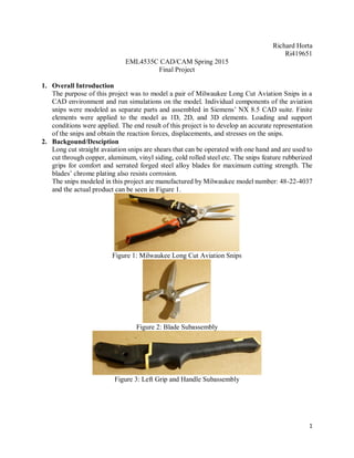
The snips modeled in this project are manufactured by Milwaukee model number: 48-22-4037
and the actual product can be seen in Figure 1.
Figure 1: Milwaukee Long Cut Aviation Snips
Figure 2: Blade Subassembly
Figure 3: Left Grip and Handle Subassembly
2. 2
Figure 4: Right Grip and Handle Subassembly
3. CAD Model
3.1 Handle
Figure 5: Handle
3. 3
Step H-1: Sketch Handle
The outline of the handle was created by
making a sketch on the X-Y plane and
replicating the geometry in Figure H-1.
Figures H-2 through H-4 give a more
detailed view of the sketch.
Figure H-1: Sketch of Handle
5. 5
Step H-2: Extrude
Geometry
The outer profile and holes
of the sketch were extruded
symmetrically 5/16’’ in each
direction. This keeps the
plane of the sketch in-line
with the center of the
extrusion.
Figure H-5: Extruded Sketch
Step H-3: Sketch Geometry
An origin was specified on the extrusion and sketch was created on a face with the dimensions in
Figure H-6.
Figure H-6: Sketch Dimensions
6. 6
Step H-4:
Extrude the sketch and apply a
Boolean Subtract condition.
Figure H-7
Figure H-8: Post Subtraction
Step H-5:
Apply 4” edge blends on the two
edges on the left and 0.4” edge
blends on the right two.
Figure H-9
7. 7
Step H-6:
Mirror the two edge
blends to make the part
symmetrical.
Figure H-10: Mirroring of edge blends
Step H-7:
Subtract the unused
triangular section in
Sketch 1 from the
geometry.
See Figure H-12 for
the result.
Figure H-11: Triangular Subtraction
8. 8
Figure H-12: Post Subtraction
Step H-8: Edge
Blends
Edge blend the curves
in the following figures
with the dimensions
provided in the
descriptions.
Figure H-13: Edge blends with a radius of 0.8”
11. 11
Step H-9 Variable Edge Blends:
The following edge blends were made along the length of the handle and varied from 0.125” to
5/16” as shown in Figure H-16.
Figure H-16: Variable Edge Blends
12. 12
Step H-10: Mirroring the
Variable Edge Blends
Mirror the edge blends to
the other side of the part as
in Figure H-17
Figure H-17: Mirrored Variable Edge Blends
Step H-11: Using the Shell
Command
Shell out the inside of the
handle with a thickness of
0.08”. Make sure to select
the cylindrical faces as well.
Figure H-18: Shelled Handle
13. 13
Step H-12: Edge Blends
Create the edge blends as in the
following figures.
Figure H-19: 0.1” Edge Blends
Figure H-20: 0.5” Edge Blends
15. 15
3.2 Left Grip
Figure LG-1: Left Grip
Figure LG-2: Left Grip Model
Step LG-1:
Save As Part 1 (Handle) in order to
create the Grip on top of the Handle.
Figure LG-3: Imported Handle
16. 16
Step LG-2:
Deactivate the Shell component.
Figure LG-4: Deactivated Shell
Step LG-3:
Hide the 3D model, create a sketch on the X-Y plane on top of
Sketch 1. Project the following curves from Sketch 1 and
convert to reference.
Figure LG-5: Sketch 1 & Projected Curves
Step LG-4:
17. 17
Create the Grip profile as seen in Figure LG-6.
Figure LG-6: Left Grip Profile
Step LG-5:
Extrude the profile 0.31875” in order
to make the Grip 0.1” thick.
Figure LG-7: Left Grip Profile Extrusion
18. 18
Step LG-6:
Create a Sketch on the Y-Z
Plane. Form the geometry
in Figure LG-8 and Subtract
to angle the surface.
Figure LG-8: Subtraction
Step LG-7:
Edge blend the left border
with a radius of 0.28”.
Edge Blend the sharp
finger grip edge with a
radius of 0.02”.
Edge Blend the right and
bottom borders with a
radius of 0.05”
Figure LG-9: 0.28” & 0.02” Edge Blends
Figure LG-10: 0.05” Edge Blend
19. 19
Step LG-8:
Reactivate the Handle and Subtract the
Handle from the Grip.
Figure LG-11: Handle Subtraction
Step LG-9
Make an Asymmetric Chamfer on the
edge in Figure LG-12 with distances of
0.2” & 0.1”.
Figure LG-12: Asymmetric Chamfer
20. 20
Step LG-10:
Use the Instance Geometry
command to mirror the half of
the Grip across the X-Y plane.
Figure LG-13: Instance Geometry
Step LG-11:
Combine the two halves using the
Unite command.
Figure LG-14: Unite
Step LG-12:
Create a Datum Plane On Curve. This Plane will
be tangent to the large arc on Figure LG-6
(Dimension: p220). Start the datum 0.45” down
the curve.
Create a rectangular profile with dimensions as
seen in Figure LG-15.
Figure LG-15: Rectangular Profile
21. 21
Step LG-13
Subtract the rectangle made in
the previous step to cut a notch
into the handle.
Figure LG-16: Rectangular Notch Subtraction
Finished Part
Figure LG-17: Finish Left-Hand Grip
22. 22
Figure B-1: Blade Subassembly
Figure B-2: Blade Subassembly Model
3.3 Blade
Step B-1
Create a New Part and form a Sketch on the
X-Y plane. Draw the base of the blade on the
sketch with the dimensions in Figure B-18.
Be sure to include the line perpendicular to
the arc on Dimension Rp6. This will be used
to create a plane later.
23. 23
Figure B-18: Blade Profile Sketch
Figure B-19: Completed Sketch
Step B-2:
Make the following
extrusions: Extrude the
outer boundary 0.27”
Symmetrically. Extrude the
inner circle with start and
end distances of 0.17” &
0.27” respectively.
24. 24
Figure B-20: Outer Extrusion
Figure B-21: Inner Circle Extrusion
Step B-3:
Create a Plane On Curve, Perpendicular
to the line jutting out from the initial
sketch.
Figure B-21: Datum Plane
25. 25
Step B-4:
Create a sketch on the
datum plane and create the
geometry in Figure B-22.
Extrude/Intersect the sketch
through the base of the
blade. (See Figure B-23)
Figure B-22
Figure B-23
Step B-5:
Edge blend the lines in Figure B-24 with a
radius of .1”.
Figure B-24
26. 26
Step B-6
Use the draft command with an angle of 15
degrees on the bottom edge of the base.
Figure B-25
Figure B-26: Post Draft
27. 27
Step B-7
Create a sketch on the X-Y Plane and create the
profile of the blade.
Figure B-27: Blade Profile Sketch
Step B-8
Create the following edge blends.
Blend the edge on Figure B-28 0.1”
Blend the edges on Figure B-29 0.2”
Figure B-28
Figure B-29
36. 36
Start new assembly. Import 2 blades
Use a Fit constraint on the cylindrical faces
Use a Touch Align for the faces in contact. Assembly 1 complete
Create new subassembly. Import Left grip and handle
Bond Components. Subassembly complete
37. 37
Start New Subassembly. Import Right grip and Handle.
Bond Components. Subassembly complete
Create new Assembly. Import the two subassemblies. Import 2 blades
Move parts apart. Rotate right grip 180 degrees. Fix Left grip
40. 40
5. FEM
5.1 Overview
Summary
Siemens NX 8.5 software enabled accurate simulations of the snips by modeling the
geometry with 1D, 2D, and 3D elements and providing loading and support conditions. The results
were accurate for the loading at the pin joints and bending stresses when compared to the hand
calculations. This model successfully represented the snips.
FE Model
Deflected Plot- Displacement
41. 41
5.2 FE Model (Idealized Part)
Step FE-1
Right click on assembly_snip.prt and select New FEM and Simulation.
Leave everything on default.
Step FE-2
Promote parts
Step FE-3
Mid-Surface handles
48. 48
Step FE-11
Copy and reflect meshes
Step FE-12
Use duplicate nodes and merge them together
Step FE-13
Use element edges to verify that the halves form one part
49. 49
Step FE-14
Go to 3D tetrahedral mesh and apply CTETRA(10) to each of the blades separately.
Mesh Type Size [in.] Thickness [in.] Material
Handle CQUAD4 0.05 0.08 Steel
2D Blade CQUAD4 0.05 0.26 Steel
3D Blade CTETRA10 0.1 N/A Steel
CQUAD4 was selected to model the handles and part of the blades to made an idealized part that
was not overly stiff and could model the geometry accurately without using up too much
processing power.
The CTETRA10 for the blades were selected to give an accurate representation of the model’s
complex geometry.
50. 50
5.4 FE Assembly (RBE2, CBUSH, CBAR)
Step FE-15
Create a node between nodes on the tips of the blades
Step FE-16
Create CBAR elements between nodes on the tip
Step FE-17
Initial meshes
51. 51
Step FE-18
Create 2 Nodes at the center of the holes for the pins on the handle. Create 2 RBE2 Elements.
Step FE-19
Create a third node and RBE2 Element for the blade.
52. 52
Step FE-20
Create a Bar Element to weld the two RBE2 elements for the handle together. Create a CBUSH
element at the center RBE2.
Step FE-21
Create 2 RBE2 1D connections for the Yellow handle
53. 53
Step FE-22
Create a CBAR Element to connect the RBE2’s.
Step FE-23
Create 2 RBE2 Connections for the red handle.
Step FE-24
Add CBUSH elements.
54. 54
Step FE-25
Edit the properties of the bushings to only allow rotation about the z-axis.
Step FE-26
Edit Mesh Associated Data for all bushings and Enable CSYS Override to incorporate the
coordinate system.
Step FE-27
Create two RBE2 Connections, one for each blade. Use the feature angle node method to select
multiple nodes.
55. 55
Step FE-28
Create a CBUSH Element to connect the two RBE2’s.
Mesh Type Radius [in.] Material
Polyurethane Bar CBAR 0.1 Polyurethane
Bar 1 CBAR 0.09375 Steel
Bar 2 CBAR 0.118 Steel
56. 56
5.5 FE Model Check:
Use the Show Adjacent command to find the elements directly connected to the upper RBE2.
6. Simulation
6.1 Glue
Step SIM-1
Create 4 New Regions in the Simulation to glue the 2D blade elements to the 3D ones.
Step SIM-2
Use the Edge-to-Surface Gluing command and glue the respective regions together.
58. 58
6.2 Loading and Support
Step SIM-3
Apply 10 lb forces to the handles.
Step SIM-4
Apply User Defined Constraint to eliminate DOF 3 motion.
Step SIM-5
Apply a Fixed Constraint to the center of the Nylon bar.
Step SIM-6
Create a New Group for the bushings and the Nylon bar.
59. 59
Step SIM-7
Modify the Solution attributes and change SPC Forces and Forces to print. Use the bushing
group to narrow down the results.
Step SIM-8
Run the Solution.
Change the material of the nylon bar to polyurethane.
Step SIM-9
Set up a new Coordinate system for the polyurethane bar.
Step SIM-10
Use the Assign Nodal CSYS command. Select all nodes and set them to Cartesian and to follow
the new Coordinate System.
60. 60
d4 = 6.6340in
d3 = 1.0463in
d2 = 1.8618in
d1 = 3.8428in
Step SIM-11
Split the handle in order to make a section by using the Split Body command.
61. 61
Sectioned Handle
Step SIM-12
Create a New Beam Section by using the face of the geometry. Define the coordinate system and
the horizontal orientation.
62. 62
Checking the YY Stress at the section shows a stress of 3967.162 psi
Investigating the part of the handle in compression shows a stress of -3941.204 psi
64. 64
Stress Element Nodal- YY for Handle
From F06 File:
F O R C E S I N B A R E L E M E N T S (C B A R)
ELEMENT BEND-MOMENT END-A BEND-MOMENT END-B - SHEAR - AXIAL
ID. PLANE 1 PLANE 2 PLANE 1 PLANE 2 PLANE 1 PLANE 2 FORCE TORQUE
25499 -1.151965E-17 8.326673E-17 1.720995E-04 -6.008815E-02 -4.797879E-04 1.675168E-01 -3.070636E+01 5.421011E-20
25500 -1.585387E-04 6.014295E-02 -5.153033E-12 1.572764E-09 -4.419823E-04 1.676696E-01 -3.070638E+01 -2.032879E-20
F O R C E S I N B U S H E L E M E N T S (C B U S H)
ELEMENT-ID FORCE-X FORCE-Y FORCE-Z MOMENT-X MOMENT-Y MOMENT-Z
0 25506 6.339595E+01 -9.262472E-02 -1.058724E+00 3.384903E-01 5.803779E-01 0.0
0 25512 2.658252E+01 -1.436692E+00 -1.471523E+00 7.017227E-01 1.460913E-01 0.0
0 25513 2.681345E+01 1.358670E+00 4.471477E-01 -1.273036E-01 -7.364157E-02 0.0
0 25516 9.410229E+01 -1.371416E-01 -1.226394E+00 1.664132E+00 1.879049E-02 0.0
0 25523 -6.339598E+01 9.266259E-02 1.058877E+00 -3.359801E-01 5.390553E-01 0.0
68. 68
N [lb] Dx [lb] Dy [lb] Cx [lb] Cy [lb] Bx [lb] By[lb]
Bending
Stress
Compression
[psi]
Bending
Stress
Tension
[psi]
Hand
Calculation 30.7200 94.1230 0.0000 -53.4040 0.0000 -63.4040 0.0000 -4017.06 3175.08
NX Calculation 30.7060 94.1020 -0.1371 -53.3890 0.1593 -63.3960 0.0927 -3941.20 3967.16
% Error 0.046% 0.022% - 0.0281% - 0.0126% - 1.89% 24.95%
7. Question
7.1
Why is the “User defined constraints” that kill DOF3 on both handles needed?
3D elements do not have rotational stiffness. DOF 3 for both handles is fixed to prevent the
handles, and therefore the snip assembly, from twisting about the axis of the polyurethane
CBAR.
What DOFs can be transferred from the polyurethane CBAR to the 3D tetra elements?
Only translational degrees of freedom. (DOF 1, 2, 3)
7.2
In the sim, what “method” is used to pick the nodes on a flat face for the surface region?
Surface Region- Feature Angle Element Face.
And the nodes on the edge region?
Edge Region- Feature Element Edges
8. Summary
This project was to demonstrate the viability of Siemens NX 8.5 software in modeling a pair
of aviation grade snips. The geometry was developed in a CAD environment and finite elements
were applied to simplify the simulation. The results of the simulations accurately modeled the
forces, displacements, and stresses on the snips when compared to hand calculations. This project
also increased familiarity in NX 8.5’s vast suite of commands and options. Applications of this
knowledge could be utilized in developing other complex computer models in the engineering
field.
69. 69
9. Appendix
Original dimensions and figures were obtained from resources posted by Shenghong Zhang and
Richard Zarda Ph.D.
PowerPoint Presentations:
https://webcourses.ucf.edu/courses/1077548/files/folder/Lab%2520Handout?preview=42752544
https://webcourses.ucf.edu/courses/1077548/files/folder/Lab%2520Handout?preview=42914087
https://webcourses.ucf.edu/courses/1077548/files/folder/Lab%2520Handout?preview=43079820
https://webcourses.ucf.edu/courses/1077548/files/folder/Lab%2520Handout?preview=43194629
https://webcourses.ucf.edu/courses/1077548/files/folder/Lab%2520Handout?preview=43595855
https://webcourses.ucf.edu/courses/1077548/files/folder/Lab%2520Handout?preview=43903522
https://webcourses.ucf.edu/courses/1077548/files/folder/Lab%2520Handout?preview=44008328
https://webcourses.ucf.edu/courses/1077548/files/folder/Lab%2520Handout?preview=44221643
https://webcourses.ucf.edu/courses/1077548/files/folder/Lab%2520Handout?preview=44467580
Youtube Videos:
https://www.youtube.com/watch?v=0mnygnnZNWI&list=PLQPYjyAxkS8jntb-
APS4BqA9lPLifu8NK&index=1
https://www.youtube.com/watch?v=606Uxjgd3co&list=PLQPYjyAxkS8jntb-
APS4BqA9lPLifu8NK&index=2
https://www.youtube.com/watch?v=a70iwWUX1bw&list=PLQPYjyAxkS8jntb-
APS4BqA9lPLifu8NK&index=3
https://www.youtube.com/watch?v=qPz6IiRoxvc&list=PLQPYjyAxkS8jntb-
APS4BqA9lPLifu8NK&index=4
https://www.youtube.com/watch?v=GJ6uQYJSUdY&list=PLQPYjyAxkS8jntb-
APS4BqA9lPLifu8NK&index=5
https://www.youtube.com/watch?v=ZbhBIBclVmM&list=PLQPYjyAxkS8jntb-
APS4BqA9lPLifu8NK&index=6
https://www.youtube.com/watch?v=6bLA3y_EJJM&list=PLQPYjyAxkS8jntb-
APS4BqA9lPLifu8NK&index=7
https://www.youtube.com/watch?v=K8T-UC8lWgI&list=PLQPYjyAxkS8jntb-
APS4BqA9lPLifu8NK&index=8
https://www.youtube.com/watch?v=EfLvrVfNuig&list=PLQPYjyAxkS8jntb-
APS4BqA9lPLifu8NK&index=9
https://www.youtube.com/watch?v=xZ5hs6Pyzqo&list=PLQPYjyAxkS8jntb-
APS4BqA9lPLifu8NK&index=10
https://www.youtube.com/watch?v=7jzpImoQlmk&list=PLQPYjyAxkS8jntb-
APS4BqA9lPLifu8NK&index=11
------------------------------------------------------------
SECTION INFORMATION
------------------------------------------------------------
Section name: User Defined Solid
Type of section: Face of Solid
70. 70
Section properties:
Area = 0.10650508136 (in^2)
Centroid, Z = 0.00000253080 (in)
Centroid, Y = -0.37434713928 (in)
Shear Center, Z = 0.00000000000 (in)
Shear Center, Y = 0.00000000000 (in)
Eccentricity, Z = -0.00000253080 (in)
Eccentricity, Y = 0.37434713928 (in)
Principal Angle, Beta = 0.00000000000 (degree)
Moment of Inertia, Iz = 0.00279771791 (in^4)
Moment of Inertia, Iy = 0.00543780352 (in^4)
Moment of Inertia, Iyz = 0.00000000000 (in^4)
Principal Moment of Inertia, Izz = 0.00543780352 (in^4)
Principal Moment of Inertia, Iyy = 0.00279771791 (in^4)
Torsional Constant, K = 0.00021863218 (in^4)
Warping Constant, Cw = 0.00008246472 (in^6)
Shear Factor along y axis, K1 = 0.60199019879
Shear Factor along z axis, K2 = 0.29279996192
Location of stress recovery points (extreme fibers):
Stress Recovery Point, C(z) = 0.00000038249 (in)
Stress Recovery Point, C(y) = -0.13111800000 (in)
Stress Recovery Point, D(z) = 0.31250000000 (in)
Stress Recovery Point, D(y) = -0.68207500000 (in)
Stress Recovery Point, E(z) = -0.31250000000 (in)
Stress Recovery Point, E(y) = -0.68207500000 (in)
Stress Recovery Point, F(z) = -0.31250000000 (in)
Stress Recovery Point, F(y) = -0.44361800000 (in)