1. TEAM 7
MAE 263A Project 2 - Making DARwIn mini Move
By -
Vishank Bhatia (304758488), Wudhidham Prachumsri (204004866)
Agraj Sobti (6468587240), Gacia Kekejian (304759614)
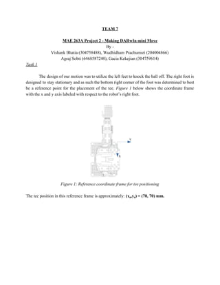
Task 1
The design of our motion was to utilize the left feet to knock the ball off. The right foot is
designed to stay stationary and as such the bottom right corner of the foot was determined to best
be a reference point for the placement of the tee. Figure 1 below shows the coordinate frame
with the x and y axis labeled with respect to the robot’s right foot.
Figure 1: Reference coordinate frame for tee positioning
The tee position in this reference frame is approximately: (x0,y0) = (70, 70) mm.
2. During the trial runs of our motion, a piece of white paper was utilized to accurately place the tee
(Figure 2).
Figure 2: Tee positioning with pre-marked paper
Task 2
The left foot of the DARWIN Mini will knock off the ball by doing a back kick . This
motion requires the robot to balance on its right feet while extending its left leg backwards.
Using the reference plane shown in Figure 1,. The angle at which the ball will be knocked off,
projected onto the floor plane, is approximately 90 degrees from the X-axis. Figure 3 below
shows a projected view of the knock off angle. Also shown is the approximate angle shown in a
three-dimensional model of the robot motion generated in Solidworks CAD software.
3. (a)
(b)
Figure 3: (a)Direction of the ball’s motion projected onto the floor view (b)Direction of ball’s
motion projected onto a side view
Task 3
SolidWorks:
The motion of the robot was created using multiple techniques. Firstly, the robot was
modeled in Solidworks 3D CAD including accurate link lengths and joint coordinate frames such
that the full motion of the robot could be easily visualized. Figure 4 below shows the modeled
DARwIn mini robot in its initial position.
Figure 4: 3D CAD model representing DARwIn mini
4. The 3D model allowed for easy manipulation of the joints as well as easy extraction of the
necessary joint angles. The model also allowed for approximation of the center of mass (shown
in Figure 4 above) which aided in determining how to properly balance the robot on one feet. Figure 5
below shows the motion of the robot from initial position to its kick, the robot then reverses these position
to return to initial position.
Figure 5: (Clockwise from top left) Motion profile for the kick
To verify the Solidworks motion profile, the link angles were extracted for each of the motion
position. A Matlab code was written to calculate the forward kinematics of the motion: the
resulting position vector of the left foot was used to verify that the motion modeled in
Solidworks was correct. To create the matlab code transformation matrices generated in Project 1
was used. Below shows the process for determining the transformation matrix of the left foot
during the final kick motion. This matrix produced the position and coordinate angles that
matched those from the Solidworks motion simulation.
5. Matlab:
The general transformation matrix from the base frame {0} to the left foot frame {LF} is a chain
product of the transformation matrices for all adjacent joints along this chain . It is given by:
The transformation matrix from the base frame {0} to the left foot frame {LF} for the left foot
back kick is also the chain product of the transformation matrices for all the adjacent joints along
this chain, however at specific joint angles for each of the transformation matrix . It is given by:
The matrix given below shows the transformation required to knock off the ball using a back
kick with respect to the base frame.
R+ Motion:
Our configurations also were simulated on the R+ Motion 2.0 software, to visualize the
collective motion profile of the robot and also to serve as a cross check. One of the
configurations as simulated on the software is shown in Figure 6. While creating the
configurations it was made sure that none of the joint angles exceeded the range of motion of the
robot.
Using these three techniques - Solidworks, Matlab, and R+ Motion - we were able to accurately
create the motion profile necessary for kicking the ball while balancing on one foot, as well as
generate the entertaining celebratory dance moves that follows the kick.
6. Figure 6 : One of the configurations as simulated on R+ Motion 2.0
Task 4
The full motion profile for the robot kick and it’s dance moves has been copied below in
Appendix A. The robot performs the kick between time step 0.0 and time step 11.5, the rest of
the profile constitutes the bow and the belly dance motion. The robot is very happy to have
knocked the ball off the tee! (Note: the motion profile below was entered with t instead of ‘tab’
to save space, a full motion profile will also be uploaded)