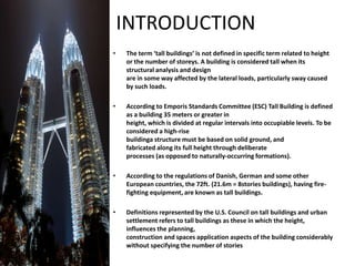
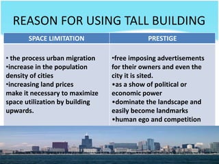
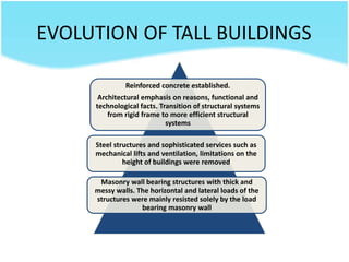
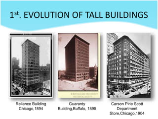
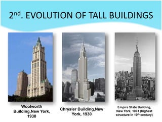
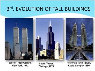
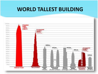
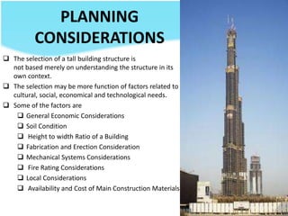
SlideShare a Scribd company logo
TALL BUILDING
LECT 3
INTRODUCTION
• The term ‘tall buildings’ is not defined in specific term related to height
or the number of storeys. A building is considered tall when its
structural analysis and design
are in some way affected by the lateral loads, particularly sway caused
by such loads.
• According to Emporis Standards Committee (ESC) Tall Building is defined
as a building 35 meters or greater in
height, which is divided at regular intervals into occupiable levels. To be
considered a high-rise
buildinga structure must be based on solid ground, and
fabricated along its full height through deliberate
processes (as opposed to naturally-occurring formations).
• According to the regulations of Danish, German and some other
European countries, the 72ft. (21.6m = 8stories buildings), having fire-
fighting equipment, are known as tall buildings.
• Definitions represented by the U.S. Council on tall buildings and urban
settlement refers to tall buildings as these in which the height,
influences the planning,
construction and spaces application aspects of the building considerably
without specifying the number of stories
THE FACTS ABOUT TALL
BUILDING…
REASON FOR USING TALL BUILDING
SPACE LIMITATION PRESTIGE
• the process urban migration
•increase in the population
density of cities
•increasing land prices
make it necessary to maximize
space utilization by building
upwards.
•free imposing advertisements
for their owners and even the
city it is sited.
•as a show of political or
economic power
•dominate the landscape and
easily become landmarks
•human ego and competition
EVOLUTION OF TALL BUILDINGS
Reinforced concrete established.
Architectural emphasis on reasons, functional and
technological facts. Transition of structural systems
from rigid frame to more efficient structural
systems
Steel structures and sophisticated services such as
mechanical lifts and ventilation, limitations on the
height of buildings were removed
Masonry wall bearing structures with thick and
messy walls. The horizontal and lateral loads of the
structures were mainly resisted solely by the load
bearing masonry wall
1st. EVOLUTION OF TALL BUILDINGS
Reliance Building
Chicago,1894
Guaranty
Building,Buffalo, 1895
Carson Pirie Scott
Department
Store,Chicago,1904
2nd. EVOLUTION OF TALL BUILDINGS
Woolworth
Building,New York,
1930
Chrysler Building,New
York, 1930
Empire State Building,
New York, 1931 (highest
structure in 19th century)
3rd. EVOLUTION OF TALL BUILDINGS
World Trade Centre,
New York,1972
Sears Tower,
Chicago,1974
Petronas Twin Tower,
Kuala Lumpur,1996
WORLD TALLEST BUILDING
TRY TO GET LISTS OF A WORLD
TALLEST BUILDINGS
PLANNING
CONSIDERATIONS
 The selection of a tall building structure is
not based merely on understanding the structure in its
own context.
 The selection may be more function of factors related to
cultural, social, economical and technological needs.
 Some of the factors are
 General Economic Considerations
 Soil Condition
 Height to width Ratio of a Building
 Fabrication and Erection Consideration
 Mechanical Systems Considerations
 Fire Rating Considerations
 Local Considerations
 Availability and Cost of Main Construction Materials
GENERAL ECONOMIC CONSIDERATIONS
 How much the projects costs to build.
 How much the finished project costs to operate
(e.g
expenses associated with utilities, maintenance,
insurance, taxes, interest on borrowed money)
 As the height of the building increases, more
and more space is needed for structure,
mechanical systems and elevators, leaving less
rental space.
 The costs of elevators and mechanical systems
increase with height.
 Cost for sophisticated construction equipment
as building get taller
SOIL CONDITION
 The performance of a building is dependent on t
he strength of the soil which it is founded.
 The foundation or substructure binds the
superstructure to the soil.
 If the bearing capacity of the soil is rather low,
piles or caissons may be required to reach the
proper foundation support.
HEIGHT TO WIDTH RATIO
OF A BUILDING
• As the minimum height-to-
width ratio increases, so
should the building’s inherent
stiffness
• The stiffness of the building
structure is dependent on
size and number of bays,
structural systems and
rigidity of members and
connections.
• The general height-to-width for a
plane frame structure in the range
of 5 to 7
FABRICATION AND ERECTION
CONSIDERATION
 The planning of fabrication and
erection procedures may indicate
important factors concerning structural
systems selection.
 Should be a minimum number of structural pie
ces to shorten construction time, complicated
closed form shapes should be avoided and
field welding should be minimized.
Mechanical Systems
Considerations
 Average more than one-third of
total tall building costs.
 Effects on the building overall
appearance and economic
selection of a structural systems
FIRE RATING
CONSIDERATIONS
 Almost all floors are beyond the reach of fire truck ladders, firefighting and rescue
action are from the inside of a building.
 Total emergency evacuation is impossible within a reasonably short period of time.
 Must be able to ensure the following:
 structural integrity for a certain period of time.
 confinement of the fire, to prevent it from spreading to certain building areas.
 adequate exit systems.
 effective smoke and fire detection systems.
 sprinklers and necessary smoke and heat venting
LOCAL
CONSIDERATIONS
For example, height limitation, zoning regulations
AVAILABILITY AND COST OF
MAIN CONSTRUCTION
MATERIALS
If a desired material is hard to acquire,
it may delay the building schedule and
add significantly to building costs
DESIGN CONSIDERATION
METHOD OF CONSTRUCTION
• CONVENTIONAL?
– In Malaysia, in-situ reinforced concrete is the norm for
constructing tall buildings. Skilled and unskilled workers
experienced in such work and the associated machinery
and materials are readily available. Pre-cast concrete is
sometimes used in low and medium rise residential
buildings. Concrete is either mixed on site or ready-mixed.
The concrete is poured into a hopper and usually lifted by
crane to the final position. The concrete is emptied in the
formwork, vibrated and cured.
• INDUSTRIALISED?
– Prefabrication do not necessary has to be in a factory located away
from the site. The prefabricated components could be built on a
production line on site. But if the high rise building has limited space,
this approach is not suitable.
– The principle of prefabrication is that the components should be made
at a place where workers could work safely and comfortably, thus
ensuring better quality and then transported to the site to be
assembled in their final positions. This principle could be used for
many types of components that are normally associated with in-situ
production. It is safer and better quality work is provided if these
components could be assembled on site and then lifted in its
assembled form to its final position rather than the normal practice of
in situ production. For example, reinforcement cages for the columns
and beams could be fabricated on the ground and then lifted by lift to
be placed at their final positions.
• STEEL OR REINFORCED CONCRETE?
– Reinforced concrete is the normal way of constructing high rise buildings in Malaysia.
This is partially due to the abundance of limestone and the setting up of several large
cement factories around Malaysia. Steel rebar is manufactured in Malaysia but hot
rolled structural steel has to be imported. One often quoted advantage of using
structural is that unlike reinforced concrete, it is a ‘dry’ form of construction involving
only assembly of the steel thus a shorter period of time. However, the use of steel
structural members for the structural frame of the building in Malaysia requires a period
of preplanning and takes account of transport times as these have to be sourced from
India, South Korea, China and Japan where there are hot rolled steel producers. This
consumes some of the so-called time savings. In addition, the assembly of the steel
structural frame needs the involvement of teams of highly skilled structural steel
workers and crane operators. These persons are mostly found in North America and
Europe. Their wages are relatively higher than the imported Indonesian, Bangadeshi and
Vietnamese workers. Furthermore, there is an available pool of foreign workers who
have had sufficient experience and some measure of skill in concreting despite them not
having any formal training in concreting. The major drawback of reinforced concrete is
that it is a wet process and needs more working space.
• SPECIAL TECHNIQUES?
– Sometimes the architects of tall buildings wish to create
exclusivity of their designs by employing innovative
construction techniques and structural systems.
– The use of innovation construction techniques must take
into account the economic availability of local and foreign
workers and consultants who are skilled and capable of
handling the technology. It must be remembered that new
systems will have teething problems and time will be spent
solving these problems during the construction period.
ARCHITECTURAL CONSIDERATION
• The shape of a tall building is basically a long vertical
box or cylinder. There is limited scope to create
innovative building shapes .
• Architects give tall buildings their identity by the way
they design the facade or outside appearance of the
building. They also design the interior finishes of the
building.
• When an architect designs the floor plan of the
building, he has to aim for maximum floor area to
sell or rent to possible tenants.
• He has to leave aside space on the floor plan for the service
core area and the building occupiers’ circulation paths. In
the building service core area, the architect allocate space
for the:-
– toilets,
– the riser cables for electricity and telecommunication
– lift shafts
– staircases
– plumbing pipes for drainage, sewerage and water supply
– airconditioning and ventilation riser ducts
– airconditioning chilled water pipes
BUILDING SERVICES
CORE AREA
• With so many things to put in the core area, the
architects try to reduce the amount of core areas.
• In addition, the architect may leave aside certain
floors to house the airconditioning plant, the water
tanks for water supply, airconditioning and fire
fighting systems, and the electicity distribution
equipment.
• These floors are usually in the basement, at the roof
or in floors where giant internal beams or girders
called outriggers are located.
Air Conditioning System
TIME CONSUMING
• Tenants in tall buildings make the journey from their
top floor offices to the outside the building at
ground level to eat. This will be too time consuming
and tiring, especially in a supertall building.
• Thus the architect will try to provide areas for
canteens, restaurants, shops and other facilities
within the building plan especially if it is a tall or
supertall building.
• In this way, people do not have to leave the building
for lunch or to shop or for leisure. In some supertall
buildings such as the Sears Tower, ‘sky lobbies’ are
provided at certain floors to house shops, eating and
recreational places.
• Thus, a supertall building is normally a city with a
city. We can see that the more taller a building is, the
more space is used for the building services and the
less the usable floor space per level.
Service core area
Tenant’s usable
space area
Circulation space
The floor plan of the 78 storey Central Plaza in
Hong Kong
STRUCTURAL CONSIDERATION
• The structural system is an integrated system
of the arrangement of members of the
structure so that it can withstand several
types of loads such as below:-
– Live and Dead Load
– Wind Load
– Differential Temperature Load
– Vibration Load
– Impact Load
Designing for Live and Dead Loads
• The loads exerted on a building are generally vertical due to
dead and live gravity loads. The structure transfers the vertical
loads as well as the horizontal loads to the ground. The
building can be structurally divided into two parts :-
i. Superstructure.
This consists of the floors, walls and roof that are generally above ground
level. In addition to the loads of the superstructure, there are the loads of
equipment, machinery, M&E services and people inside the
superstructure that have to be transferred to the substructure.
ii. Substructure.
This consists of the foundations that lay below ground level. The
foundations may be piles, caissons, rafts, pads or even strips. The
materials used are generally reinforced concrete or concrete encased
steel members.
Superstructure
Walls
Suspension system
Frame cages
SUPERSTRUCTURE
Hanger Bridge Catenary
System
• The main function of the vertical loading subsystem
is to transfer the dead and live loads of the
superstructure to the substructure. There are many
ways of transferring the loads.
• Walls
– Most walls in a tall building are non-load bearing. The self-
weights of these non-load bearing walls are transmitted to
the ground via the floor slab and then the columns
– Load bearing walls in tall buildings are generally made of
reinforced concrete. They are normally used as shear walls
and together with a frame cage.
FRAME CAGES
• Known as a framed structure, skeleton structure and
moment resisting frames
• The “frame cage” consisted of rolled iron beams and
stanchions arranged in square or rectangular grid.
The loads of the walls and floors are transferred to
the beams and column grid to the ground. Most
modern buildings use the frame cage system. Iron
have been superseded by high strength structural
steel and reinforced concrete.
• In order to transfer lateral loads to the ground, mega-bracing
is sometimes used in the steel frame. These are giant diagonal
members that span between giant mega columns. The mega
braces transfer the loads of the floors to the mega columns.
The mega columns transfer the loads to the foundations.
• Compared to load bearing walls, the self-weight of the frame
cage is less although the point loads at the base of the
columns may be rather high. Frame cage construction is also
relatively faster to erect especially when structural steel is the
material used. The frame cage structural members also
occupies a smaller area of the building footprint. This allows
more usable floor space for the building.
• Steel frame cages are more
susceptible to wind loads due to
their relatively lighter self-weight.
Thus expensive damping
mechanisms have to be
incorporated into the structure.
• Reinforced concrete frame cages
are more rigid and thus are less
likely to sway in the wind.
However, excessive wind loads
may cause tensile cracks in the
structure and thus additional
measures must be taken to
increase the R.C. frame cage’s
tensile strength.
DIAGRID
• The latest innovation to the
frame system is the diagrid.
Instead of box-like grid
arrangements of beams and
columns, a building with a
diagrid structure uses diagonal
members that function as both
the beam and column.. The
most famous example of the
diagrid frame structure is that
of the London’s Swiss Re
building.
DIAGRID
• Diagrid system
• The diagrid is often used for
the perimeter exterior wall.
It is usually part of a tube-
within-tube structural
system.
• Examples IBM building,
Pittsburgh
SUSPENSION SYSTEM
• As the name implies, the floors of the buildings are
suspended over a long span. The supports for these floors
may be towers, hangers or catenaries. The main advantage
of these systems is the ability to provide a column free
ground floor which could then be used as a public space,
exhibition areas etc. The other floors also enjoy column
free space which allows an infinite number of space
partitioning options.
• There are three main types of suspension system:
• Hanger
• Bridge
• Catenary systems:-
Hanger systems
• In this system, the floor and wall loads are
transmitted upwards through vertical tensile
members to outrigger arms. The loads are then
transferred from the outriggers to one or more
pier towers that transmit the loads to the
ground. The tensile members can be hangers or
cables. The pier towers are either monolithic
reinforced concrete load bearing walls or a steel
framed tower.
• There are few buildings using
this system. These buildings
are difficult to design and
construct.
• Examples of buildings with
hanger systems are Hong
Kong and Shanghai Bank
building in Hong Kong, Sabah
Foundation Building in Kota
Kinabalu and the AAP building
in Sydney.
Catenary system
• The catenary system usually consisted of a pair of catenary
members that span between two towers of the building.
Both catenary members lie on the long facades of the
building. The catenary spans in a U-shaped configuration
somewhat like a suspension bridge between the towers.
Each catenary member supports hangers and columns.
These hangers and columns support the floor structure.
• There are two examples of this catenary system. This is the
10 story Federal Reserve Bank of Minneapolis in USA and
the 10 story First Exchange House, London.
The original design of the catenary structural system of the
Minneapolis Federal Reserve Bank (right) and photo of as-
built building (left)
• The higher the building, the more exposed it is
to wind forces. The wind exerts horizontal
loads on the building that causes the building
to sway. This is normally felt in medium rise
and tall buildings that have steel structural
frames.
• Buildings that have reinforced concrete
structural frames do not suffer this problem.
Designing For Horizontal Forces
• Another horizontal force that has to be considered
by engineers is the force due to earthquakes.
• The type of movement due to an earthquake is
actually up and down, and from side to side. In other
words, during an earthquake, the building feels like it
is on a boat.
• Buildings in earthquake areas are normally fitted
with shock absorbers in their foundations and
structural frames.
• There are three main ways of preventing
swaying (or oscillation) of tall buildings due to
wind forces
– STRUCTURAL METHOD
– DAMPING METHOD
– AERODYNAMIC METHOD
STRUCTURAL
METHOD
DAMPING
METHOD
AERODYNAMIC METHOD
Shear Wall
Brace frame and moment
resistant frame systems
Tubes systems
Composite systems
Passive Dampers
Active dampers
Friction dampers
Passive tuned mass dampers
Passive pendulum dampers
Tuned Liquid Dampers (aka Tuned
Sloshing Water Dampers (TSWD)
aka Tuned Liquid Column Dampers
(TLCD))
Structural Method
• The oscillation is minimized or removed
increased stiffening the structural frame.
Four ways can be used :
• making the building stiffer by using increasing its
weight
• fixing structural tie members (braces) in the building
structural frame
• reducing the size of the vertical bays in the frame and
• guying the structure to the ground by structural ties
Structural Method (Shear Walls)
• Monolithic shear walls of reinforced concrete are used to
provide stiffness. By using a monolithic wall, the wall will
be more heavier and thus stiffer. Yet increasing weight has
a disadvantage. It means that the foundations have to be
stronger and this in turn means more cost.
• Therefore heavy shear walls may not be the suitable
solution. Stiff but relatively slender shear walls are
preferable. Shear walls can be pre-stressed to increase
stiffness yet give a relatively thin wall.
• By the way, shear walls do not have to be of reinforced
concrete, it may be made of reinforced steel plate and
even reinforced masonry.
• Shear walls are located in one or more of
the following locations on the building
footprint plan.
• Central core of building
• Ends or corners of building
• As vertical fins for a tower
• As the vertical tubular wall of the tower
• Monolithic shear walls of
reinforced concrete are
popular in Malaysian tall
buildings because reinforced
concrete structural frames are
used in most buildings.
• Monolithic shear walls of
reinforced concrete are often
used to enclose the building
services core area. These walls
are natural firewalls that
enclose the lift shafts, escape
stairways and electrical risers.
Shear wall
Shear wall
Building with shear walls at its ends
Brace frame and moment resistant
frame systems
• Increasing the mass of building is the most effective way to resist
lateral forces (ASCE, 2005) but this is relatively uneconomic today. The
trend is for lighter but stiffer buildings
• i. Moment resistant frame
• The moment resisting frame is a three dimensional grid of linear
columns and beams. The members of the frames are connected
each other using rigid or semi-rigid connections.
• ii. Braced frame
• Moment resistant frames can be stiffened by adding braces to
vertical and horizontal bays of the frame. A megaframe structure
also use megabraces to stiffen the megaframe and to transmit the
floor loads of the building to megacolumns that rests on the
foundations
• Some vertical and/or horizontal bays of
the structural frame are braced. This
creates stiffness to the overall frame. The
arrangement of the braces usually result
in vertical truss configuration or
perimeter belt trusses or outrigger
trusses. In some frames, a vertical
megatruss is used insteaad of a shear wall
to further stiffen the frame.
• A megaframe can be built to carry the
floors of the building. To stiffen the
megaframe, megabraces are placed
across the vertical megabays. Thus the
building behaves like a vertical megatruss.
• A mega space frame can be used
to support the floors of the
building. The concept of load
transmittance is the same as that
of the vertical megatruss
• Many structural steel ‘pencil thin’
towers use the concept of the
‘vertical trusses’ to resist lateral
forces
• There are many configurations of the moment
resistant frame and shear walls to increase the
building resistance to the wind. The systems
are:-
– Tube system
– Composite system
Tubes
Systems
– Load bearing columns of the
exterior perimeter are
placed closely together to
form a ‘tube’. Tubes can also
be formed from
configurations of shear walls
that form a tube. Shear walls
can be perimeter walls or
cores.
– Towers use either tubular r.c.
‘stem’ structures or large
diameter steel tubular ‘stem’
structures to resist lateral
forces.
• Another way to create a building tube is to have an outer
perimeter of mega columns. A building tube may have mega
bracing, mega columns and mega beams that form a
perimeter box truss for the building. A perimeter box space
truss configuration can be used instead of the box truss
• Several configurations of the tube system can be found
– - Single tube
– - Tube within tube (One Shell Plaza Building)
– - Bundling of tubes (Sears Tower)
– - Braced tubes (see Alcoa Building)
One Shell Plaza building,
Houston Texas.Tube in
tube structure. Note the
closed spaced columns in
the outer tube.
Bundled tube system as used
in the Sears Tower, Chicago,
U.S.A.
View of Sears Tower structure
• In tall buildings using ‘tube lateral systems’, further
lateral restraint can be provided by reducing the
vertical bending moment of the buildings.
• The building structure is designed such two or more
vertical zones of floors share the bending moment.
Each zone will thus experience a lower bending
moment.
• The overall effect is that the building structure will
not experience a much lower bending moment and
less sway.
• There are three ways of doing this:-
i. Using perimeter structural belts every
certain height of building
• The perimeter structural belts are located on the
external perimeter wall line of the building. These
structures can be trusses, girders or monolithic walls
and usually one story in height. They are positioned
at every other number of floors so as to ‘break up’
the building into two or more vertical zones
ii. Using outriggers at every certain height of the
building
• The outriggers are located within the building. On plan, they
connect the outer ‘tube’ with inner ‘tube’ structure. A group of
outriggers are positioned at every other number of floors so as to
‘break up’ the building into two or more vertical zones Outriggers
can be formed from trusses or girders or monolithic walls and
usually one floor in height.
• The monolithic wall outrigger will usually have perforations to
allow the people circulation and service runs
iii. Combined systems
• Combination of structural belt and outriggers.
• Outriggers of a floor level is tied together by the
structural belt located on the exterior perimeter face of
the building
Composite / Hybrid
• The computer allows engineers to shorten the time for designing tall
building. It also allows more complicated designs to be feasible.
• More and more composite systems that combine several structural
systems such as shear walls, tubes and bracing systems together.
• Some types are as follows;
– Shear walls and skeleton frame acting as tubes. Shear walls are placed on
certain positions of the exterior perimeter of building frame
– Tube within tube system using shear wall core and columnade tube on
exterior perimeter
– Tube within tube system with shear wall core and braced mega frame for
exterior perimeter of building.
– Tube with tube system using shear wall construction. Interior wall fins connect
the exterior and interior tubes together.
– Tube system of steel construction with guying cables
Damping Devices
• These devices are generally used in lighter tall
buildings (normally of steel frame construction).
Heavy buildings use mass and stiffness as natural
dampers (normally r.c. frame buildings). Thus
dampers are seldom found in r.c. building for
resisting wind forces.
• There are several types of dampers:-
– Passive dampers
– Active dampers
• Passive Dampers
– There are two types i.e. the hydraulic piston dampers and
the viscoelastic friction dampers:-
• Hydraulic pistons are placed at various points in the structure.
These pistons are filled with oil. The pistons absorb most of the
resulting movement or vibration due to wind. They are usually
fitted in the vertical bays in a bracing configuration.
• Viscoelastic materials are placed at various points in the structural
frame. They are sandwiched between the steel plate connections
of the structural frame. The material inserts provide shear
resistance to the oscillation forces. See friction dampers
• Friction dampers
– The friction damper consists of a steel plate that is
sandwiched by two plates A special lubricant coats
the area where the plates touch so that stability is
maintained even after repeated deformation of
the plates due to movment. When the building
sways during a high wind or earthquake, the
plates absorb energy by friction and thus minimise
the swaying.
Application for the bolt-type friction damper
Friction damper
• Passive tuned mass dampers
– This damper type consists of a sliding or horizontal
moving mass tuned to move in reaction to the
horizontal movement of the building. Either large
springs or dampers are fitted to the mass and the
building structure. Passive tuned dampers are
usually found at the topmost floor. A good
example is the Citi Corp Centre building in New
York.
Example of Tuned Mass Dampers in Citi
Corp Centre Building in New York
• Passive pendulum dampers
– This is a suspended mass acting as pendulum. The
concept is similar to the passive tuned massive
damper. The new Taipei 101 building uses a 730-
ton pendulum tuned mass damper (TMD). Eight
steel cables form a sling to support the ball, while
eight viscous pistons act like shock absorbers
when the sphere swings.
Passive pendulum TMD of Taipei 101 building
• Tuned Liquid Dampers (a.k.a. Tuned Sloshing
Water Dampers (TSWD) a.k.a. Tuned Liquid
Column Dampers (TLCD))
– This damper type consists of two or more tanks (or liquid
columns) whose water contents change in response to lateral
forces. The damper can be a pair of large tanks or number of
small ones.
Tuned Liquid Dampers
(a.k.a. Tuned Sloshing
Water Dampers (TSWD)
a.k.a. Tuned Liquid Column
Dampers (TLCD))
• Active dampers
– Active tuned mass dampers are tuned to a certain
frequency. Computers allow it to adapt itself to a
big range of tuning. This makes it more effective.
– Actuators such as pistons move the mass in
response to the actual horizontal movement of
the building. The main disadvantage is its reliance
on electricity. Backup electricity supply is needed
in case of blackouts
Active Damper – Simulation for building
Kyobashi Seiwa Building using Active
Mass Damper
Active tuned mass damper system in Kyobashi Seiwa
building, Tokyo, Japan
Tuned Liquid Damper at Wall Centre building,
Vancouver, Canada
• Active-passive tuned mass dampers. In these
damping systems, there is active damper actuator
working with the passive damper. The active mass
damper works within the capacity range of the
actuator. But, outside the range, the passive damper
and the hydraulic become detached and the damping
is provided by the passive damper. This method
allows the use of a smaller sized passive damper at a
lower cost. This method is used primarily for lateral
forces due to earthquakes.
Aerodynamic
• Tower cross-sectional plan is designed to have
minimum air turbulence that could cause swaying of
the building. Reduction of air turbulence can be
obtained by:-
i. Have a circular plan rather than rectangular or
square plan for tower
ii. Flattening (or tapering) of the corners
iii. Providing for perforations at either the corners or top
of the tower
iv.Having channels in the building silhouette that allow the
wind to be channeled away from the face of the
building
Thank You
BSS552 LECT 2.pptx

More Related Content

Similar to BSS552 LECT 2.pptx

High rise construction
High rise constructionHigh rise construction
High rise construction
akkshay jawlekar
 
Mod. 1.pptx
Mod. 1.pptxMod. 1.pptx
Mod. 1.pptx
MrinmayeeGanage1
 
TALL BUILDINGS
TALL BUILDINGSTALL BUILDINGS
TALL BUILDINGS
Abhijit Pal
 
PREFAB CONSTRUCTION .pdf
PREFAB CONSTRUCTION .pdfPREFAB CONSTRUCTION .pdf
PREFAB CONSTRUCTION .pdf
GourhariBiswas1
 
Construction Technology III (Group Assignment) - Semester 3
Construction Technology III (Group Assignment) - Semester 3Construction Technology III (Group Assignment) - Semester 3
Construction Technology III (Group Assignment) - Semester 3
Yee Len Wan
 
national building code
national building codenational building code
national building code
Ruhiya Garg
 
Monolithic concrete construction system
Monolithic concrete construction systemMonolithic concrete construction system
Monolithic concrete construction system
chirag aggarwal
 
Building technology report
Building technology reportBuilding technology report
Building technology report
Chong Yi Hui
 
Site report
Site reportSite report
Site report
Eric Teo
 
Bc open pre fabricated construction system
Bc open pre fabricated construction systemBc open pre fabricated construction system
Bc open pre fabricated construction system
Anuj Singhal
 
MIVAN CONSTRUCTION TECHNOLOGY for const
MIVAN CONSTRUCTION TECHNOLOGY  for constMIVAN CONSTRUCTION TECHNOLOGY  for const
MIVAN CONSTRUCTION TECHNOLOGY for const
PradeepPandya1
 
Pre engineering building
Pre engineering buildingPre engineering building
Pre engineering building
Rathin Rakshit
 
Prefab Building CR ppt.pptx
Prefab Building CR ppt.pptxPrefab Building CR ppt.pptx
Prefab Building CR ppt.pptx
dharmveersingh60
 
case study of shanghai world finance centre.
case study of shanghai world finance centre.case study of shanghai world finance centre.
case study of shanghai world finance centre.
Chiranjita Jibhkate
 
Structural systems in high rise building and analysis methods
Structural systems in high rise building and analysis methodsStructural systems in high rise building and analysis methods
Structural systems in high rise building and analysis methods
DP NITHIN
 
Form-woks-additional.pptx
Form-woks-additional.pptxForm-woks-additional.pptx
Form-woks-additional.pptx
ssuserc0bf9b
 
ADVANCED TECHNIQUES IN CONSTRUCTIONS IN HIGH RISE BUILDINGS
ADVANCED TECHNIQUES IN CONSTRUCTIONS IN HIGH RISE BUILDINGSADVANCED TECHNIQUES IN CONSTRUCTIONS IN HIGH RISE BUILDINGS
ADVANCED TECHNIQUES IN CONSTRUCTIONS IN HIGH RISE BUILDINGS
ASHOK KUMAR TIWARY
 
J.S. Daniel paper for high rise building construction cycle
J.S. Daniel paper for high rise building construction cycleJ.S. Daniel paper for high rise building construction cycle
J.S. Daniel paper for high rise building construction cycleJ.S. Daniel
 
muslim project ppt.pptx
muslim project ppt.pptxmuslim project ppt.pptx
muslim project ppt.pptx
EmHetchMaidabino
 

Similar to BSS552 LECT 2.pptx (20)

High rise construction
High rise constructionHigh rise construction
High rise construction
 
Mod. 1.pptx
Mod. 1.pptxMod. 1.pptx
Mod. 1.pptx
 
TALL BUILDINGS
TALL BUILDINGSTALL BUILDINGS
TALL BUILDINGS
 
PREFAB CONSTRUCTION .pdf
PREFAB CONSTRUCTION .pdfPREFAB CONSTRUCTION .pdf
PREFAB CONSTRUCTION .pdf
 
Construction Technology III (Group Assignment) - Semester 3
Construction Technology III (Group Assignment) - Semester 3Construction Technology III (Group Assignment) - Semester 3
Construction Technology III (Group Assignment) - Semester 3
 
Site report
Site reportSite report
Site report
 
national building code
national building codenational building code
national building code
 
Monolithic concrete construction system
Monolithic concrete construction systemMonolithic concrete construction system
Monolithic concrete construction system
 
Building technology report
Building technology reportBuilding technology report
Building technology report
 
Site report
Site reportSite report
Site report
 
Bc open pre fabricated construction system
Bc open pre fabricated construction systemBc open pre fabricated construction system
Bc open pre fabricated construction system
 
MIVAN CONSTRUCTION TECHNOLOGY for const
MIVAN CONSTRUCTION TECHNOLOGY  for constMIVAN CONSTRUCTION TECHNOLOGY  for const
MIVAN CONSTRUCTION TECHNOLOGY for const
 
Pre engineering building
Pre engineering buildingPre engineering building
Pre engineering building
 
Prefab Building CR ppt.pptx
Prefab Building CR ppt.pptxPrefab Building CR ppt.pptx
Prefab Building CR ppt.pptx
 
case study of shanghai world finance centre.
case study of shanghai world finance centre.case study of shanghai world finance centre.
case study of shanghai world finance centre.
 
Structural systems in high rise building and analysis methods
Structural systems in high rise building and analysis methodsStructural systems in high rise building and analysis methods
Structural systems in high rise building and analysis methods
 
Form-woks-additional.pptx
Form-woks-additional.pptxForm-woks-additional.pptx
Form-woks-additional.pptx
 
ADVANCED TECHNIQUES IN CONSTRUCTIONS IN HIGH RISE BUILDINGS
ADVANCED TECHNIQUES IN CONSTRUCTIONS IN HIGH RISE BUILDINGSADVANCED TECHNIQUES IN CONSTRUCTIONS IN HIGH RISE BUILDINGS
ADVANCED TECHNIQUES IN CONSTRUCTIONS IN HIGH RISE BUILDINGS
 
J.S. Daniel paper for high rise building construction cycle
J.S. Daniel paper for high rise building construction cycleJ.S. Daniel paper for high rise building construction cycle
J.S. Daniel paper for high rise building construction cycle
 
muslim project ppt.pptx
muslim project ppt.pptxmuslim project ppt.pptx
muslim project ppt.pptx
 

Recently uploaded

一比一原版(MMU毕业证书)曼彻斯特城市大学毕业证成绩单如何办理
一比一原版(MMU毕业证书)曼彻斯特城市大学毕业证成绩单如何办理一比一原版(MMU毕业证书)曼彻斯特城市大学毕业证成绩单如何办理
一比一原版(MMU毕业证书)曼彻斯特城市大学毕业证成绩单如何办理
7sd8fier
 
一比一原版(UW毕业证)西雅图华盛顿大学毕业证如何办理
一比一原版(UW毕业证)西雅图华盛顿大学毕业证如何办理一比一原版(UW毕业证)西雅图华盛顿大学毕业证如何办理
一比一原版(UW毕业证)西雅图华盛顿大学毕业证如何办理
kecekev
 
Maximize Your Content with Beautiful Assets : Content & Asset for Landing Page
Maximize Your Content with Beautiful Assets : Content & Asset for Landing Page Maximize Your Content with Beautiful Assets : Content & Asset for Landing Page
Maximize Your Content with Beautiful Assets : Content & Asset for Landing Page
pmgdscunsri
 
EASY TUTORIAL OF HOW TO USE CAPCUT BY: FEBLESS HERNANE
EASY TUTORIAL OF HOW TO USE CAPCUT BY: FEBLESS HERNANEEASY TUTORIAL OF HOW TO USE CAPCUT BY: FEBLESS HERNANE
EASY TUTORIAL OF HOW TO USE CAPCUT BY: FEBLESS HERNANE
Febless Hernane
 
White wonder, Work developed by Eva Tschopp
White wonder, Work developed by Eva TschoppWhite wonder, Work developed by Eva Tschopp
White wonder, Work developed by Eva Tschopp
Mansi Shah
 
一比一原版(CITY毕业证书)谢菲尔德哈勒姆大学毕业证如何办理
一比一原版(CITY毕业证书)谢菲尔德哈勒姆大学毕业证如何办理一比一原版(CITY毕业证书)谢菲尔德哈勒姆大学毕业证如何办理
一比一原版(CITY毕业证书)谢菲尔德哈勒姆大学毕业证如何办理
9a93xvy
 
UNIT V ACTIONS AND COMMANDS, FORMS AND CONTROLS.pptx
UNIT V ACTIONS AND COMMANDS, FORMS AND CONTROLS.pptxUNIT V ACTIONS AND COMMANDS, FORMS AND CONTROLS.pptx
UNIT V ACTIONS AND COMMANDS, FORMS AND CONTROLS.pptx
GOWSIKRAJA PALANISAMY
 
Коричневый и Кремовый Деликатный Органический Копирайтер Фрилансер Марке...
Коричневый и Кремовый Деликатный Органический Копирайтер Фрилансер Марке...Коричневый и Кремовый Деликатный Органический Копирайтер Фрилансер Марке...
Коричневый и Кремовый Деликатный Органический Копирайтер Фрилансер Марке...
ameli25062005
 
Can AI do good? at 'offtheCanvas' India HCI prelude
Can AI do good? at 'offtheCanvas' India HCI preludeCan AI do good? at 'offtheCanvas' India HCI prelude
Can AI do good? at 'offtheCanvas' India HCI prelude
Alan Dix
 
vernacular architecture in response to climate.pdf
vernacular architecture in response to climate.pdfvernacular architecture in response to climate.pdf
vernacular architecture in response to climate.pdf
PrabhjeetSingh219035
 
Design Thinking Design thinking Design thinking
Design Thinking Design thinking Design thinkingDesign Thinking Design thinking Design thinking
Design Thinking Design thinking Design thinking
cy0krjxt
 
一比一原版(Glasgow毕业证书)格拉斯哥大学毕业证成绩单如何办理
一比一原版(Glasgow毕业证书)格拉斯哥大学毕业证成绩单如何办理一比一原版(Glasgow毕业证书)格拉斯哥大学毕业证成绩单如何办理
一比一原版(Glasgow毕业证书)格拉斯哥大学毕业证成绩单如何办理
n0tivyq
 
Design Thinking Design thinking Design thinking
Design Thinking Design thinking Design thinkingDesign Thinking Design thinking Design thinking
Design Thinking Design thinking Design thinking
cy0krjxt
 
Storytelling For The Web: Integrate Storytelling in your Design Process
Storytelling For The Web: Integrate Storytelling in your Design ProcessStorytelling For The Web: Integrate Storytelling in your Design Process
Storytelling For The Web: Integrate Storytelling in your Design Process
Chiara Aliotta
 
一比一原版(Brunel毕业证书)布鲁内尔大学毕业证成绩单如何办理
一比一原版(Brunel毕业证书)布鲁内尔大学毕业证成绩单如何办理一比一原版(Brunel毕业证书)布鲁内尔大学毕业证成绩单如何办理
一比一原版(Brunel毕业证书)布鲁内尔大学毕业证成绩单如何办理
smpc3nvg
 
原版定做(penn毕业证书)美国宾夕法尼亚大学毕业证文凭学历证书原版一模一样
原版定做(penn毕业证书)美国宾夕法尼亚大学毕业证文凭学历证书原版一模一样原版定做(penn毕业证书)美国宾夕法尼亚大学毕业证文凭学历证书原版一模一样
原版定做(penn毕业证书)美国宾夕法尼亚大学毕业证文凭学历证书原版一模一样
gpffo76j
 
一比一原版(UAL毕业证书)伦敦艺术大学毕业证成绩单如何办理
一比一原版(UAL毕业证书)伦敦艺术大学毕业证成绩单如何办理一比一原版(UAL毕业证书)伦敦艺术大学毕业证成绩单如何办理
一比一原版(UAL毕业证书)伦敦艺术大学毕业证成绩单如何办理
708pb191
 
UNIT IV-VISUAL STYLE AND MOBILE INTERFACES.pptx
UNIT IV-VISUAL STYLE AND MOBILE INTERFACES.pptxUNIT IV-VISUAL STYLE AND MOBILE INTERFACES.pptx
UNIT IV-VISUAL STYLE AND MOBILE INTERFACES.pptx
GOWSIKRAJA PALANISAMY
 
PORTFOLIO FABIANA VILLANI ARCHITECTURE.pdf
PORTFOLIO FABIANA VILLANI ARCHITECTURE.pdfPORTFOLIO FABIANA VILLANI ARCHITECTURE.pdf
PORTFOLIO FABIANA VILLANI ARCHITECTURE.pdf
fabianavillanib
 
一比一原版(Bolton毕业证书)博尔顿大学毕业证成绩单如何办理
一比一原版(Bolton毕业证书)博尔顿大学毕业证成绩单如何办理一比一原版(Bolton毕业证书)博尔顿大学毕业证成绩单如何办理
一比一原版(Bolton毕业证书)博尔顿大学毕业证成绩单如何办理
h7j5io0
 

Recently uploaded (20)

一比一原版(MMU毕业证书)曼彻斯特城市大学毕业证成绩单如何办理
一比一原版(MMU毕业证书)曼彻斯特城市大学毕业证成绩单如何办理一比一原版(MMU毕业证书)曼彻斯特城市大学毕业证成绩单如何办理
一比一原版(MMU毕业证书)曼彻斯特城市大学毕业证成绩单如何办理
 
一比一原版(UW毕业证)西雅图华盛顿大学毕业证如何办理
一比一原版(UW毕业证)西雅图华盛顿大学毕业证如何办理一比一原版(UW毕业证)西雅图华盛顿大学毕业证如何办理
一比一原版(UW毕业证)西雅图华盛顿大学毕业证如何办理
 
Maximize Your Content with Beautiful Assets : Content & Asset for Landing Page
Maximize Your Content with Beautiful Assets : Content & Asset for Landing Page Maximize Your Content with Beautiful Assets : Content & Asset for Landing Page
Maximize Your Content with Beautiful Assets : Content & Asset for Landing Page
 
EASY TUTORIAL OF HOW TO USE CAPCUT BY: FEBLESS HERNANE
EASY TUTORIAL OF HOW TO USE CAPCUT BY: FEBLESS HERNANEEASY TUTORIAL OF HOW TO USE CAPCUT BY: FEBLESS HERNANE
EASY TUTORIAL OF HOW TO USE CAPCUT BY: FEBLESS HERNANE
 
White wonder, Work developed by Eva Tschopp
White wonder, Work developed by Eva TschoppWhite wonder, Work developed by Eva Tschopp
White wonder, Work developed by Eva Tschopp
 
一比一原版(CITY毕业证书)谢菲尔德哈勒姆大学毕业证如何办理
一比一原版(CITY毕业证书)谢菲尔德哈勒姆大学毕业证如何办理一比一原版(CITY毕业证书)谢菲尔德哈勒姆大学毕业证如何办理
一比一原版(CITY毕业证书)谢菲尔德哈勒姆大学毕业证如何办理
 
UNIT V ACTIONS AND COMMANDS, FORMS AND CONTROLS.pptx
UNIT V ACTIONS AND COMMANDS, FORMS AND CONTROLS.pptxUNIT V ACTIONS AND COMMANDS, FORMS AND CONTROLS.pptx
UNIT V ACTIONS AND COMMANDS, FORMS AND CONTROLS.pptx
 
Коричневый и Кремовый Деликатный Органический Копирайтер Фрилансер Марке...
Коричневый и Кремовый Деликатный Органический Копирайтер Фрилансер Марке...Коричневый и Кремовый Деликатный Органический Копирайтер Фрилансер Марке...
Коричневый и Кремовый Деликатный Органический Копирайтер Фрилансер Марке...
 
Can AI do good? at 'offtheCanvas' India HCI prelude
Can AI do good? at 'offtheCanvas' India HCI preludeCan AI do good? at 'offtheCanvas' India HCI prelude
Can AI do good? at 'offtheCanvas' India HCI prelude
 
vernacular architecture in response to climate.pdf
vernacular architecture in response to climate.pdfvernacular architecture in response to climate.pdf
vernacular architecture in response to climate.pdf
 
Design Thinking Design thinking Design thinking
Design Thinking Design thinking Design thinkingDesign Thinking Design thinking Design thinking
Design Thinking Design thinking Design thinking
 
一比一原版(Glasgow毕业证书)格拉斯哥大学毕业证成绩单如何办理
一比一原版(Glasgow毕业证书)格拉斯哥大学毕业证成绩单如何办理一比一原版(Glasgow毕业证书)格拉斯哥大学毕业证成绩单如何办理
一比一原版(Glasgow毕业证书)格拉斯哥大学毕业证成绩单如何办理
 
Design Thinking Design thinking Design thinking
Design Thinking Design thinking Design thinkingDesign Thinking Design thinking Design thinking
Design Thinking Design thinking Design thinking
 
Storytelling For The Web: Integrate Storytelling in your Design Process
Storytelling For The Web: Integrate Storytelling in your Design ProcessStorytelling For The Web: Integrate Storytelling in your Design Process
Storytelling For The Web: Integrate Storytelling in your Design Process
 
一比一原版(Brunel毕业证书)布鲁内尔大学毕业证成绩单如何办理
一比一原版(Brunel毕业证书)布鲁内尔大学毕业证成绩单如何办理一比一原版(Brunel毕业证书)布鲁内尔大学毕业证成绩单如何办理
一比一原版(Brunel毕业证书)布鲁内尔大学毕业证成绩单如何办理
 
原版定做(penn毕业证书)美国宾夕法尼亚大学毕业证文凭学历证书原版一模一样
原版定做(penn毕业证书)美国宾夕法尼亚大学毕业证文凭学历证书原版一模一样原版定做(penn毕业证书)美国宾夕法尼亚大学毕业证文凭学历证书原版一模一样
原版定做(penn毕业证书)美国宾夕法尼亚大学毕业证文凭学历证书原版一模一样
 
一比一原版(UAL毕业证书)伦敦艺术大学毕业证成绩单如何办理
一比一原版(UAL毕业证书)伦敦艺术大学毕业证成绩单如何办理一比一原版(UAL毕业证书)伦敦艺术大学毕业证成绩单如何办理
一比一原版(UAL毕业证书)伦敦艺术大学毕业证成绩单如何办理
 
UNIT IV-VISUAL STYLE AND MOBILE INTERFACES.pptx
UNIT IV-VISUAL STYLE AND MOBILE INTERFACES.pptxUNIT IV-VISUAL STYLE AND MOBILE INTERFACES.pptx
UNIT IV-VISUAL STYLE AND MOBILE INTERFACES.pptx
 
PORTFOLIO FABIANA VILLANI ARCHITECTURE.pdf
PORTFOLIO FABIANA VILLANI ARCHITECTURE.pdfPORTFOLIO FABIANA VILLANI ARCHITECTURE.pdf
PORTFOLIO FABIANA VILLANI ARCHITECTURE.pdf
 
一比一原版(Bolton毕业证书)博尔顿大学毕业证成绩单如何办理
一比一原版(Bolton毕业证书)博尔顿大学毕业证成绩单如何办理一比一原版(Bolton毕业证书)博尔顿大学毕业证成绩单如何办理
一比一原版(Bolton毕业证书)博尔顿大学毕业证成绩单如何办理
 

BSS552 LECT 2.pptx

  • 2. INTRODUCTION • The term ‘tall buildings’ is not defined in specific term related to height or the number of storeys. A building is considered tall when its structural analysis and design are in some way affected by the lateral loads, particularly sway caused by such loads. • According to Emporis Standards Committee (ESC) Tall Building is defined as a building 35 meters or greater in height, which is divided at regular intervals into occupiable levels. To be considered a high-rise buildinga structure must be based on solid ground, and fabricated along its full height through deliberate processes (as opposed to naturally-occurring formations). • According to the regulations of Danish, German and some other European countries, the 72ft. (21.6m = 8stories buildings), having fire- fighting equipment, are known as tall buildings. • Definitions represented by the U.S. Council on tall buildings and urban settlement refers to tall buildings as these in which the height, influences the planning, construction and spaces application aspects of the building considerably without specifying the number of stories
  • 3. THE FACTS ABOUT TALL BUILDING…
  • 4. REASON FOR USING TALL BUILDING SPACE LIMITATION PRESTIGE • the process urban migration •increase in the population density of cities •increasing land prices make it necessary to maximize space utilization by building upwards. •free imposing advertisements for their owners and even the city it is sited. •as a show of political or economic power •dominate the landscape and easily become landmarks •human ego and competition
  • 5. EVOLUTION OF TALL BUILDINGS Reinforced concrete established. Architectural emphasis on reasons, functional and technological facts. Transition of structural systems from rigid frame to more efficient structural systems Steel structures and sophisticated services such as mechanical lifts and ventilation, limitations on the height of buildings were removed Masonry wall bearing structures with thick and messy walls. The horizontal and lateral loads of the structures were mainly resisted solely by the load bearing masonry wall
  • 6. 1st. EVOLUTION OF TALL BUILDINGS Reliance Building Chicago,1894 Guaranty Building,Buffalo, 1895 Carson Pirie Scott Department Store,Chicago,1904
  • 7. 2nd. EVOLUTION OF TALL BUILDINGS Woolworth Building,New York, 1930 Chrysler Building,New York, 1930 Empire State Building, New York, 1931 (highest structure in 19th century)
  • 8. 3rd. EVOLUTION OF TALL BUILDINGS World Trade Centre, New York,1972 Sears Tower, Chicago,1974 Petronas Twin Tower, Kuala Lumpur,1996
  • 12. TRY TO GET LISTS OF A WORLD TALLEST BUILDINGS
  • 13. PLANNING CONSIDERATIONS  The selection of a tall building structure is not based merely on understanding the structure in its own context.  The selection may be more function of factors related to cultural, social, economical and technological needs.  Some of the factors are  General Economic Considerations  Soil Condition  Height to width Ratio of a Building  Fabrication and Erection Consideration  Mechanical Systems Considerations  Fire Rating Considerations  Local Considerations  Availability and Cost of Main Construction Materials
  • 14. GENERAL ECONOMIC CONSIDERATIONS  How much the projects costs to build.  How much the finished project costs to operate (e.g expenses associated with utilities, maintenance, insurance, taxes, interest on borrowed money)  As the height of the building increases, more and more space is needed for structure, mechanical systems and elevators, leaving less rental space.  The costs of elevators and mechanical systems increase with height.  Cost for sophisticated construction equipment as building get taller
  • 15. SOIL CONDITION  The performance of a building is dependent on t he strength of the soil which it is founded.  The foundation or substructure binds the superstructure to the soil.  If the bearing capacity of the soil is rather low, piles or caissons may be required to reach the proper foundation support.
  • 16. HEIGHT TO WIDTH RATIO OF A BUILDING • As the minimum height-to- width ratio increases, so should the building’s inherent stiffness • The stiffness of the building structure is dependent on size and number of bays, structural systems and rigidity of members and connections. • The general height-to-width for a plane frame structure in the range of 5 to 7
  • 17. FABRICATION AND ERECTION CONSIDERATION  The planning of fabrication and erection procedures may indicate important factors concerning structural systems selection.  Should be a minimum number of structural pie ces to shorten construction time, complicated closed form shapes should be avoided and field welding should be minimized.
  • 18. Mechanical Systems Considerations  Average more than one-third of total tall building costs.  Effects on the building overall appearance and economic selection of a structural systems
  • 19. FIRE RATING CONSIDERATIONS  Almost all floors are beyond the reach of fire truck ladders, firefighting and rescue action are from the inside of a building.  Total emergency evacuation is impossible within a reasonably short period of time.  Must be able to ensure the following:  structural integrity for a certain period of time.  confinement of the fire, to prevent it from spreading to certain building areas.  adequate exit systems.  effective smoke and fire detection systems.  sprinklers and necessary smoke and heat venting
  • 20. LOCAL CONSIDERATIONS For example, height limitation, zoning regulations
  • 21. AVAILABILITY AND COST OF MAIN CONSTRUCTION MATERIALS If a desired material is hard to acquire, it may delay the building schedule and add significantly to building costs
  • 23. METHOD OF CONSTRUCTION • CONVENTIONAL? – In Malaysia, in-situ reinforced concrete is the norm for constructing tall buildings. Skilled and unskilled workers experienced in such work and the associated machinery and materials are readily available. Pre-cast concrete is sometimes used in low and medium rise residential buildings. Concrete is either mixed on site or ready-mixed. The concrete is poured into a hopper and usually lifted by crane to the final position. The concrete is emptied in the formwork, vibrated and cured.
  • 24. • INDUSTRIALISED? – Prefabrication do not necessary has to be in a factory located away from the site. The prefabricated components could be built on a production line on site. But if the high rise building has limited space, this approach is not suitable. – The principle of prefabrication is that the components should be made at a place where workers could work safely and comfortably, thus ensuring better quality and then transported to the site to be assembled in their final positions. This principle could be used for many types of components that are normally associated with in-situ production. It is safer and better quality work is provided if these components could be assembled on site and then lifted in its assembled form to its final position rather than the normal practice of in situ production. For example, reinforcement cages for the columns and beams could be fabricated on the ground and then lifted by lift to be placed at their final positions.
  • 25. • STEEL OR REINFORCED CONCRETE? – Reinforced concrete is the normal way of constructing high rise buildings in Malaysia. This is partially due to the abundance of limestone and the setting up of several large cement factories around Malaysia. Steel rebar is manufactured in Malaysia but hot rolled structural steel has to be imported. One often quoted advantage of using structural is that unlike reinforced concrete, it is a ‘dry’ form of construction involving only assembly of the steel thus a shorter period of time. However, the use of steel structural members for the structural frame of the building in Malaysia requires a period of preplanning and takes account of transport times as these have to be sourced from India, South Korea, China and Japan where there are hot rolled steel producers. This consumes some of the so-called time savings. In addition, the assembly of the steel structural frame needs the involvement of teams of highly skilled structural steel workers and crane operators. These persons are mostly found in North America and Europe. Their wages are relatively higher than the imported Indonesian, Bangadeshi and Vietnamese workers. Furthermore, there is an available pool of foreign workers who have had sufficient experience and some measure of skill in concreting despite them not having any formal training in concreting. The major drawback of reinforced concrete is that it is a wet process and needs more working space.
  • 26. • SPECIAL TECHNIQUES? – Sometimes the architects of tall buildings wish to create exclusivity of their designs by employing innovative construction techniques and structural systems. – The use of innovation construction techniques must take into account the economic availability of local and foreign workers and consultants who are skilled and capable of handling the technology. It must be remembered that new systems will have teething problems and time will be spent solving these problems during the construction period.
  • 27. ARCHITECTURAL CONSIDERATION • The shape of a tall building is basically a long vertical box or cylinder. There is limited scope to create innovative building shapes . • Architects give tall buildings their identity by the way they design the facade or outside appearance of the building. They also design the interior finishes of the building. • When an architect designs the floor plan of the building, he has to aim for maximum floor area to sell or rent to possible tenants.
  • 28. • He has to leave aside space on the floor plan for the service core area and the building occupiers’ circulation paths. In the building service core area, the architect allocate space for the:- – toilets, – the riser cables for electricity and telecommunication – lift shafts – staircases – plumbing pipes for drainage, sewerage and water supply – airconditioning and ventilation riser ducts – airconditioning chilled water pipes BUILDING SERVICES CORE AREA
  • 29. • With so many things to put in the core area, the architects try to reduce the amount of core areas. • In addition, the architect may leave aside certain floors to house the airconditioning plant, the water tanks for water supply, airconditioning and fire fighting systems, and the electicity distribution equipment. • These floors are usually in the basement, at the roof or in floors where giant internal beams or girders called outriggers are located.
  • 31. TIME CONSUMING • Tenants in tall buildings make the journey from their top floor offices to the outside the building at ground level to eat. This will be too time consuming and tiring, especially in a supertall building. • Thus the architect will try to provide areas for canteens, restaurants, shops and other facilities within the building plan especially if it is a tall or supertall building.
  • 32. • In this way, people do not have to leave the building for lunch or to shop or for leisure. In some supertall buildings such as the Sears Tower, ‘sky lobbies’ are provided at certain floors to house shops, eating and recreational places. • Thus, a supertall building is normally a city with a city. We can see that the more taller a building is, the more space is used for the building services and the less the usable floor space per level.
  • 33. Service core area Tenant’s usable space area Circulation space The floor plan of the 78 storey Central Plaza in Hong Kong
  • 34. STRUCTURAL CONSIDERATION • The structural system is an integrated system of the arrangement of members of the structure so that it can withstand several types of loads such as below:- – Live and Dead Load – Wind Load – Differential Temperature Load – Vibration Load – Impact Load
  • 35. Designing for Live and Dead Loads • The loads exerted on a building are generally vertical due to dead and live gravity loads. The structure transfers the vertical loads as well as the horizontal loads to the ground. The building can be structurally divided into two parts :- i. Superstructure. This consists of the floors, walls and roof that are generally above ground level. In addition to the loads of the superstructure, there are the loads of equipment, machinery, M&E services and people inside the superstructure that have to be transferred to the substructure. ii. Substructure. This consists of the foundations that lay below ground level. The foundations may be piles, caissons, rafts, pads or even strips. The materials used are generally reinforced concrete or concrete encased steel members.
  • 37. • The main function of the vertical loading subsystem is to transfer the dead and live loads of the superstructure to the substructure. There are many ways of transferring the loads. • Walls – Most walls in a tall building are non-load bearing. The self- weights of these non-load bearing walls are transmitted to the ground via the floor slab and then the columns – Load bearing walls in tall buildings are generally made of reinforced concrete. They are normally used as shear walls and together with a frame cage.
  • 38. FRAME CAGES • Known as a framed structure, skeleton structure and moment resisting frames • The “frame cage” consisted of rolled iron beams and stanchions arranged in square or rectangular grid. The loads of the walls and floors are transferred to the beams and column grid to the ground. Most modern buildings use the frame cage system. Iron have been superseded by high strength structural steel and reinforced concrete.
  • 39. • In order to transfer lateral loads to the ground, mega-bracing is sometimes used in the steel frame. These are giant diagonal members that span between giant mega columns. The mega braces transfer the loads of the floors to the mega columns. The mega columns transfer the loads to the foundations. • Compared to load bearing walls, the self-weight of the frame cage is less although the point loads at the base of the columns may be rather high. Frame cage construction is also relatively faster to erect especially when structural steel is the material used. The frame cage structural members also occupies a smaller area of the building footprint. This allows more usable floor space for the building.
  • 40. • Steel frame cages are more susceptible to wind loads due to their relatively lighter self-weight. Thus expensive damping mechanisms have to be incorporated into the structure. • Reinforced concrete frame cages are more rigid and thus are less likely to sway in the wind. However, excessive wind loads may cause tensile cracks in the structure and thus additional measures must be taken to increase the R.C. frame cage’s tensile strength.
  • 41. DIAGRID • The latest innovation to the frame system is the diagrid. Instead of box-like grid arrangements of beams and columns, a building with a diagrid structure uses diagonal members that function as both the beam and column.. The most famous example of the diagrid frame structure is that of the London’s Swiss Re building.
  • 42. DIAGRID • Diagrid system • The diagrid is often used for the perimeter exterior wall. It is usually part of a tube- within-tube structural system. • Examples IBM building, Pittsburgh
  • 43. SUSPENSION SYSTEM • As the name implies, the floors of the buildings are suspended over a long span. The supports for these floors may be towers, hangers or catenaries. The main advantage of these systems is the ability to provide a column free ground floor which could then be used as a public space, exhibition areas etc. The other floors also enjoy column free space which allows an infinite number of space partitioning options. • There are three main types of suspension system: • Hanger • Bridge • Catenary systems:-
  • 44. Hanger systems • In this system, the floor and wall loads are transmitted upwards through vertical tensile members to outrigger arms. The loads are then transferred from the outriggers to one or more pier towers that transmit the loads to the ground. The tensile members can be hangers or cables. The pier towers are either monolithic reinforced concrete load bearing walls or a steel framed tower.
  • 45. • There are few buildings using this system. These buildings are difficult to design and construct. • Examples of buildings with hanger systems are Hong Kong and Shanghai Bank building in Hong Kong, Sabah Foundation Building in Kota Kinabalu and the AAP building in Sydney.
  • 46. Catenary system • The catenary system usually consisted of a pair of catenary members that span between two towers of the building. Both catenary members lie on the long facades of the building. The catenary spans in a U-shaped configuration somewhat like a suspension bridge between the towers. Each catenary member supports hangers and columns. These hangers and columns support the floor structure. • There are two examples of this catenary system. This is the 10 story Federal Reserve Bank of Minneapolis in USA and the 10 story First Exchange House, London.
  • 47. The original design of the catenary structural system of the Minneapolis Federal Reserve Bank (right) and photo of as- built building (left)
  • 48. • The higher the building, the more exposed it is to wind forces. The wind exerts horizontal loads on the building that causes the building to sway. This is normally felt in medium rise and tall buildings that have steel structural frames. • Buildings that have reinforced concrete structural frames do not suffer this problem. Designing For Horizontal Forces
  • 49. • Another horizontal force that has to be considered by engineers is the force due to earthquakes. • The type of movement due to an earthquake is actually up and down, and from side to side. In other words, during an earthquake, the building feels like it is on a boat. • Buildings in earthquake areas are normally fitted with shock absorbers in their foundations and structural frames.
  • 50. • There are three main ways of preventing swaying (or oscillation) of tall buildings due to wind forces – STRUCTURAL METHOD – DAMPING METHOD – AERODYNAMIC METHOD
  • 51. STRUCTURAL METHOD DAMPING METHOD AERODYNAMIC METHOD Shear Wall Brace frame and moment resistant frame systems Tubes systems Composite systems Passive Dampers Active dampers Friction dampers Passive tuned mass dampers Passive pendulum dampers Tuned Liquid Dampers (aka Tuned Sloshing Water Dampers (TSWD) aka Tuned Liquid Column Dampers (TLCD))
  • 52. Structural Method • The oscillation is minimized or removed increased stiffening the structural frame. Four ways can be used : • making the building stiffer by using increasing its weight • fixing structural tie members (braces) in the building structural frame • reducing the size of the vertical bays in the frame and • guying the structure to the ground by structural ties
  • 53. Structural Method (Shear Walls) • Monolithic shear walls of reinforced concrete are used to provide stiffness. By using a monolithic wall, the wall will be more heavier and thus stiffer. Yet increasing weight has a disadvantage. It means that the foundations have to be stronger and this in turn means more cost. • Therefore heavy shear walls may not be the suitable solution. Stiff but relatively slender shear walls are preferable. Shear walls can be pre-stressed to increase stiffness yet give a relatively thin wall. • By the way, shear walls do not have to be of reinforced concrete, it may be made of reinforced steel plate and even reinforced masonry.
  • 54. • Shear walls are located in one or more of the following locations on the building footprint plan. • Central core of building • Ends or corners of building • As vertical fins for a tower • As the vertical tubular wall of the tower
  • 55. • Monolithic shear walls of reinforced concrete are popular in Malaysian tall buildings because reinforced concrete structural frames are used in most buildings. • Monolithic shear walls of reinforced concrete are often used to enclose the building services core area. These walls are natural firewalls that enclose the lift shafts, escape stairways and electrical risers. Shear wall Shear wall Building with shear walls at its ends
  • 56. Brace frame and moment resistant frame systems • Increasing the mass of building is the most effective way to resist lateral forces (ASCE, 2005) but this is relatively uneconomic today. The trend is for lighter but stiffer buildings • i. Moment resistant frame • The moment resisting frame is a three dimensional grid of linear columns and beams. The members of the frames are connected each other using rigid or semi-rigid connections. • ii. Braced frame • Moment resistant frames can be stiffened by adding braces to vertical and horizontal bays of the frame. A megaframe structure also use megabraces to stiffen the megaframe and to transmit the floor loads of the building to megacolumns that rests on the foundations
  • 57. • Some vertical and/or horizontal bays of the structural frame are braced. This creates stiffness to the overall frame. The arrangement of the braces usually result in vertical truss configuration or perimeter belt trusses or outrigger trusses. In some frames, a vertical megatruss is used insteaad of a shear wall to further stiffen the frame. • A megaframe can be built to carry the floors of the building. To stiffen the megaframe, megabraces are placed across the vertical megabays. Thus the building behaves like a vertical megatruss.
  • 58. • A mega space frame can be used to support the floors of the building. The concept of load transmittance is the same as that of the vertical megatruss • Many structural steel ‘pencil thin’ towers use the concept of the ‘vertical trusses’ to resist lateral forces
  • 59. • There are many configurations of the moment resistant frame and shear walls to increase the building resistance to the wind. The systems are:- – Tube system – Composite system
  • 60. Tubes Systems – Load bearing columns of the exterior perimeter are placed closely together to form a ‘tube’. Tubes can also be formed from configurations of shear walls that form a tube. Shear walls can be perimeter walls or cores. – Towers use either tubular r.c. ‘stem’ structures or large diameter steel tubular ‘stem’ structures to resist lateral forces.
  • 61. • Another way to create a building tube is to have an outer perimeter of mega columns. A building tube may have mega bracing, mega columns and mega beams that form a perimeter box truss for the building. A perimeter box space truss configuration can be used instead of the box truss • Several configurations of the tube system can be found – - Single tube – - Tube within tube (One Shell Plaza Building) – - Bundling of tubes (Sears Tower) – - Braced tubes (see Alcoa Building)
  • 62. One Shell Plaza building, Houston Texas.Tube in tube structure. Note the closed spaced columns in the outer tube.
  • 63. Bundled tube system as used in the Sears Tower, Chicago, U.S.A. View of Sears Tower structure
  • 64. • In tall buildings using ‘tube lateral systems’, further lateral restraint can be provided by reducing the vertical bending moment of the buildings. • The building structure is designed such two or more vertical zones of floors share the bending moment. Each zone will thus experience a lower bending moment. • The overall effect is that the building structure will not experience a much lower bending moment and less sway.
  • 65. • There are three ways of doing this:- i. Using perimeter structural belts every certain height of building • The perimeter structural belts are located on the external perimeter wall line of the building. These structures can be trusses, girders or monolithic walls and usually one story in height. They are positioned at every other number of floors so as to ‘break up’ the building into two or more vertical zones
  • 66. ii. Using outriggers at every certain height of the building • The outriggers are located within the building. On plan, they connect the outer ‘tube’ with inner ‘tube’ structure. A group of outriggers are positioned at every other number of floors so as to ‘break up’ the building into two or more vertical zones Outriggers can be formed from trusses or girders or monolithic walls and usually one floor in height. • The monolithic wall outrigger will usually have perforations to allow the people circulation and service runs
  • 67. iii. Combined systems • Combination of structural belt and outriggers. • Outriggers of a floor level is tied together by the structural belt located on the exterior perimeter face of the building
  • 68. Composite / Hybrid • The computer allows engineers to shorten the time for designing tall building. It also allows more complicated designs to be feasible. • More and more composite systems that combine several structural systems such as shear walls, tubes and bracing systems together. • Some types are as follows; – Shear walls and skeleton frame acting as tubes. Shear walls are placed on certain positions of the exterior perimeter of building frame – Tube within tube system using shear wall core and columnade tube on exterior perimeter – Tube within tube system with shear wall core and braced mega frame for exterior perimeter of building. – Tube with tube system using shear wall construction. Interior wall fins connect the exterior and interior tubes together. – Tube system of steel construction with guying cables
  • 69. Damping Devices • These devices are generally used in lighter tall buildings (normally of steel frame construction). Heavy buildings use mass and stiffness as natural dampers (normally r.c. frame buildings). Thus dampers are seldom found in r.c. building for resisting wind forces. • There are several types of dampers:- – Passive dampers – Active dampers
  • 70. • Passive Dampers – There are two types i.e. the hydraulic piston dampers and the viscoelastic friction dampers:- • Hydraulic pistons are placed at various points in the structure. These pistons are filled with oil. The pistons absorb most of the resulting movement or vibration due to wind. They are usually fitted in the vertical bays in a bracing configuration. • Viscoelastic materials are placed at various points in the structural frame. They are sandwiched between the steel plate connections of the structural frame. The material inserts provide shear resistance to the oscillation forces. See friction dampers
  • 71. • Friction dampers – The friction damper consists of a steel plate that is sandwiched by two plates A special lubricant coats the area where the plates touch so that stability is maintained even after repeated deformation of the plates due to movment. When the building sways during a high wind or earthquake, the plates absorb energy by friction and thus minimise the swaying.
  • 72. Application for the bolt-type friction damper Friction damper
  • 73. • Passive tuned mass dampers – This damper type consists of a sliding or horizontal moving mass tuned to move in reaction to the horizontal movement of the building. Either large springs or dampers are fitted to the mass and the building structure. Passive tuned dampers are usually found at the topmost floor. A good example is the Citi Corp Centre building in New York.
  • 74. Example of Tuned Mass Dampers in Citi Corp Centre Building in New York
  • 75. • Passive pendulum dampers – This is a suspended mass acting as pendulum. The concept is similar to the passive tuned massive damper. The new Taipei 101 building uses a 730- ton pendulum tuned mass damper (TMD). Eight steel cables form a sling to support the ball, while eight viscous pistons act like shock absorbers when the sphere swings.
  • 76. Passive pendulum TMD of Taipei 101 building
  • 77. • Tuned Liquid Dampers (a.k.a. Tuned Sloshing Water Dampers (TSWD) a.k.a. Tuned Liquid Column Dampers (TLCD)) – This damper type consists of two or more tanks (or liquid columns) whose water contents change in response to lateral forces. The damper can be a pair of large tanks or number of small ones.
  • 78. Tuned Liquid Dampers (a.k.a. Tuned Sloshing Water Dampers (TSWD) a.k.a. Tuned Liquid Column Dampers (TLCD))
  • 79. • Active dampers – Active tuned mass dampers are tuned to a certain frequency. Computers allow it to adapt itself to a big range of tuning. This makes it more effective. – Actuators such as pistons move the mass in response to the actual horizontal movement of the building. The main disadvantage is its reliance on electricity. Backup electricity supply is needed in case of blackouts
  • 80. Active Damper – Simulation for building
  • 81. Kyobashi Seiwa Building using Active Mass Damper
  • 82. Active tuned mass damper system in Kyobashi Seiwa building, Tokyo, Japan
  • 83.
  • 84. Tuned Liquid Damper at Wall Centre building, Vancouver, Canada
  • 85. • Active-passive tuned mass dampers. In these damping systems, there is active damper actuator working with the passive damper. The active mass damper works within the capacity range of the actuator. But, outside the range, the passive damper and the hydraulic become detached and the damping is provided by the passive damper. This method allows the use of a smaller sized passive damper at a lower cost. This method is used primarily for lateral forces due to earthquakes.
  • 86. Aerodynamic • Tower cross-sectional plan is designed to have minimum air turbulence that could cause swaying of the building. Reduction of air turbulence can be obtained by:- i. Have a circular plan rather than rectangular or square plan for tower ii. Flattening (or tapering) of the corners iii. Providing for perforations at either the corners or top of the tower iv.Having channels in the building silhouette that allow the wind to be channeled away from the face of the building