This document provides an overview of a summer training report completed by Avaneesh Kumar Rai at BSNL Exchange in Faizabad, Uttar Pradesh, India. The report includes acknowledgments, an introduction on BSNL and its objectives, and sections covering various telecommunication topics studied during the training, such as broadband, GSM, antennas, CDMA, wireless technologies, and fiber optics. The training aimed to provide practical exposure and understanding of technical aspects involved in the telecommunications industry.


![It is a horizontally layered network architecture instead of the
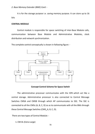
present vertically separated networks for each service. It uses packet-based
transport for all services (including voice).The access, switching,
transport, control and service functions which are integrated in today’s
switches are separated into individual network layers, which inter-work via
interfaces based on open standards. The most significant aspect is the separation of call control
from switching and transport functions
NGN APPLICATIONS – THE KEY TO
COMPETITIVE DIFFERENTIATION
1. Voice Telephony
NGNs will likely need to support various existing voice
telephony services (e.g., Call Waiting, Call Forwarding, 3-Way
Calling, various AIN features, various Centrex features, and various
CLASS features).Note, however, that NGNs are not trying to duplicate
each and every traditional voice telephony service currently offered.
Rather, they will likely attempt to support only a small percentage of
these traditional services, with an initial focus on the most
marketable voice telephony features and the features required from a
regulatory perspective.
2. Data (Connectivity) Services
Allows for the real-time establishment of connectivity between
endpoints, along with various value-added features (e.g., bandwidth-on-
demand, connection reliability/resilient Switched Virtual
Connections [SVCs], and bandwidth management/call admission
control).
1. Multimedia Services
43](https://image.slidesharecdn.com/bsnlavaneesh-141110042128-conversion-gate02/85/Bsnl-avaneesh-43-320.jpg)