Download to read offline
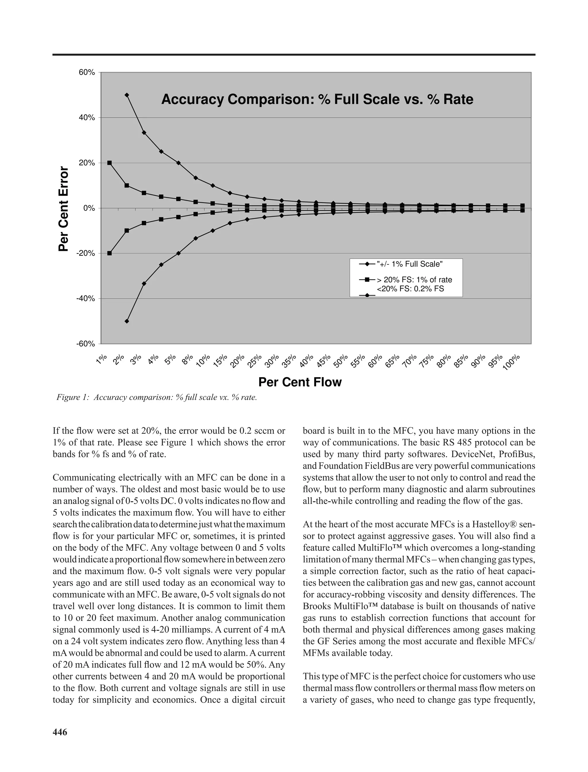

The document discusses the selection of thermal mass flow controllers (MFCs), emphasizing four key considerations: flow range, gas conditions, desired accuracy, and communications. It details how various factors, including pressure limits, temperature, and flow measurement accuracy, impact the performance of MFCs in different applications. Additionally, the document highlights advancements like the multiflo™ technology for improved accuracy across varying gas types.


