Bridge and its types
•Download as DOCX, PDF•
0 likes•204 views

Bridge and its types 00923006902338

Recommended
More Related Content
What's hot
What's hot (20)
Similar to Bridge and its types
Similar to Bridge and its types (20)
More from Salman Jailani
More from Salman Jailani (20)
Recently uploaded
Recently uploaded (20)
Bridge and its types
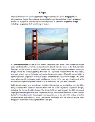
- 1. Bridge The first American iron chain suspension bridge was the Jacob's Creek Bridge (1801) in Westmoreland County, Pennsylvania, designed by inventor James Finley. Finley's bridge was the first to incorporate all of the necessary components of a Modern suspension bridge, including a suspended deck which hung by trusses. A cable-stayed bridge has one or more towers (or pylons), from which cables support the bridge deck. A distinctive feature are the cables which run directly from the tower to the deck, normally forming a fan-likepattern or a series of parallellines.This is in contrast to the modern suspension bridge, where the cables supporting the deck are suspended vertically from the main cable, anchored at both ends of the bridge and running between the towers. The cable-stayed bridge is optimal for spans longer than cantilever bridges and shorter than suspension bridges. This is the range where cantilever bridges would rapidly grow heavier if the span were lengthened, while suspension bridge cabling would not be more economical if the span were shortened. Cable-stayed bridges have been known since the 16th century and used widely since the 19th. Early examples often combined features from both the cable-stayed and suspension designs, including the famous Brooklyn Bridge. The design fell from favor through the 20th century as larger gaps were bridged using pure suspension designs, and shorter ones using various systems built of reinforced concrete. It once again rose to prominence in the later 20th century when the combination of new materials, larger construction machinery, and the need to replace older bridges all lowered the relative price of these designs.
- 2. Suspension bridges The earliest method of crossing large gaps . Early bridges realised from a walkway suspended from hanging ropes of vines To walk a lighter bridge of this type at a reasonable pace requires a particular gliding step, as the more normal walking step will induce travelling waves that can cause the traveller to pitch (uncomfortably) up and down or side-to-side. Suspension bridge realised following the simple design of early bridges. cables (catenaries) Light deck – hangers suspending the deck on catenaries Lack of stability in high winds Very flexible under concentrated loads, as the form of the cable will adapt to loading form Improved behaviour under traffic and wind loads: stiffening trusses at the level of the deck, that distributes concentrated loads over greater lengths Alternatively: restrain vertical movement of the catenaries by inclined cables attached to the top of the towers or inclined struts below the deck.Tacoma Narrows Bridge, USA, collapsed on November 7, 1940 due to wind-induced vibrations. It had been open for traffic for a few months only before collapsing. Cable-stayed bridges A cable-stayed bridge consists of one or more piers, with cables supporting the bridge deck Basic idea: reduce the span of the beam (deck) several times compared to the clear span between the piers Steel cable-stayed bridges are regarded as the most economical bridge design for spans ranging between 200 and 400 m Shorter spans: truss or box girder bridges Larger spans: suspension bridges.
- 3. Origins The origins of the suspension bridge go back a long way in history. Primitive suspension bridges, or simple crossing devices, were the forebears to today’s modern suspension bridge structures. Suspension bridges were constructed with iron chain cables over 2000 years ago in China and a similar record has been left in India. The iron suspension bridge, assumed to have originated in the Orient, appeared in Europe in the 16th century and was developed in the 18th century. Although wrought iron chain was used as the main cables in the middle of the 18th century, a rapid expansion of the center span length took place in the latter half of the 19th century triggered by the invention of steel. Today, the suspension bridge is most suitable type for very long-span bridge and actually represents 20 or more of all the longest span bridges in the world. Structural System 1. Stiffening girders/trusses: Longitudinal structures which support and distribute moving vehicle loads, act as chords for the lateral systemand secure the aerodynamic stability of the structure. 2. Main cables:
- 4. A group of parallel-wire bundled cables which support stiffening girders/trusses by hanger ropes and transfer loads to towers. 3. Main towers: Intermediate vertical structures which support main cables and transfer bridge loads to foundations. 4. Anchorages: Massive concrete blocks which anchor main cables and act as end supports of a bridge. Evolution of Modern Suspension Bridges Beginning of the Modern Suspension Bridge The modern suspension bridge originated in the 18th century when the development of the bridge structure and the production of iron started on a full-scale basis. Jacobs Creek Bridge was constructed by Finley in the United States in 1801, which had a center span of 21.3 m. The bridge’s distinguishing feature was the adoption of a truss stiffening girder which gave rigidity to the bridge to distribute the load through the hanger ropes and thus prevent excessive deformation of the cable. The construction of the Clifton Bridge with a center span of 214 m, the oldest suspension bridge now in service for cars, began in 1831 and was completed in 1864 in the United Kingdom using wrought iron chains. Progress of the Center Span Length in the First Halfof the 20th Century in the United States The aerial spinning method (AS method) used for constructing parallel wire cables was invented by Roebling during the construction of the NiagaraFalls Bridge,which was completed in 1855 with a center span of 246 m. The technology was established in the Brooklyn Bridge, completed in 1883 with a center span of 486 m, where steel wires were first used. The Brooklyn Bridge, which is hailed as the first modern suspension bridge, was constructed across New York’s East River through the self-sacrificing efforts of the Roebling family father, son, and the daughter-in-law over a period of 14 years. In 1903, the Manhattan Bridge, with a center span of 448 m, and in 1909 .
- 5. Description of Humber Suspension Bridge: The Humber Bridge (Fig. 1) located near Kingston upon Hull, England. It spans between Barton on the south coast and Hessle on the north coast, connecting the East Riding of Yorkshire and North Lincolnshire. Construction of the bridge started in 1972 and completed in 1981. The bridge has a main span of 1410 m and two side spans of 280 m and 530 m on the Hessle and Barton sides, respectively. The bridge has reinforced concrete towers of 155.5 m high above the foundation, asteelbox deck and inclined hangers. Theconnection of hangers and deck are hinged in both directions in the middle of main span.