Bike Frame Races Carbon Consumer Goods Forward

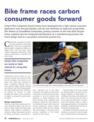
Reinforced Plastics, July/August 2003, R.H. Nelson. An article I wrote in Reinforced Plastics on the Trek OCLV bicycle frame development. An article I wrote for Reinforced Plastics on the development of the Trek line of OCLV Bicycles, which received huge mass market TV exposure when ridden to eight victories in the world's most viewed athletic event, the Tour de France. Carbon fibre composite bicycle frames have developed into a high volume consumerapplication over the past decade, and are now dominate on high-end racing bikes.Ron Nelson of ClosedMold Composites, primary inventor of the Trek OCLV bicycleframe, explains how the integrated development of a manufacturing process andframe design lead to a successful commercial product line.Lance Armstrong has ridden Trek’s composite road bike to victory in four Tour de France events.

Recommended
More Related Content
What's hot
What's hot (20)
Similar to Bike Frame Races Carbon Consumer Goods Forward
Similar to Bike Frame Races Carbon Consumer Goods Forward (20)
More from ClosedMold Composites, LLC. (CMC)
More from ClosedMold Composites, LLC. (CMC) (7)
Recently uploaded
Recently uploaded (20)
Bike Frame Races Carbon Consumer Goods Forward
- 1. 36 REINFORCEDplastics July/August 2003 C arbon fibre composites are nearly an ideal material for racing bike frames. They have exceptionally high strength to weight and stiffness to weight ratios. They also have better vibratory damping characteristics than metals, contributing to a smoother feel when riding. Carbon fibre composites are nearly an ideal material for racing bike frames. Traditionally, bicycle frames are con- structed of metal tubes joined at their ends by welding, or are brazed or sol- dered onto metal lugs, forming the frame. Composite materials have a lower density, higher specific strength and stiffness, and better damping qual- ities than traditional metals, and there- by provide an increase in frame strength and stiffness with a reduction in weight, as compared to earlier metal- lic frames. Design requirements There are many design requirements for road racing bike frames, but the fore- most are light weight and high lateral stiffness. Light weight is essential to minimize energy consumption up hills or during accelerations, and provide a more responsive feel to the rider’s movements. The stiffness characteristics of the frame are important because they contribute to how the bicycle rides. Resistance to lateral deflections and frame twisting under pedalling loads minimizes energy loss that would go into flexing the frame rather than into forward propulsion. Lateral stiffness also provides a stable feel, for example when descending or cornering, and it provides confidence in the frame’s response to rider actions. Lateral twisting of the frame around the steering column can cause self rein- forcing vibrations at high speeds, i.e. wobbling of the frame and steering col- umn. In its worst case this can cause a loss of control of the bicycle. In motor- cycles this vibratory mode is called a ‘tank slapping vibration’, referring to the handlebars oscillating back and forth so much they hit the gas tank. The ability of the frame to damp road vibrations and provide vertical compli- ance to absorb shock are also important. 0034-3617/03 ©2003 Elsevier Ltd. All rights reserved. Bike frame races carbon consumer goods forward Carbon fibre composite bicycle frames have developed into a high volume consumer application over the past decade, and are now dominate on high-end racing bikes. Ron Nelson of ClosedMold Composites, primary inventor of the Trek OCLV bicycle frame, explains how the integrated development of a manufacturing process and frame design lead to a successful commercial product line. Lance Armstrong has ridden Trek’s composite road bike to victory in four Tour de France events.
- 2. 37July/August 2003 REINFORCEDplastics This contributes to a smoother and less fatiguing ride. Carbon fibre is noted for its ability to damp road vibrations rela- tive to metal frames. Strength requirements Frame strength characteristics are something which the rider hopefully never has to experience since the frame should never break. Reliably producing high static and fatigue strengths is essential to mini- mize in service fail- ures which affect profitability, product image, and can pro- duce legal liabilities. A bicycle frame experiences several types of loads in its lifetime. The event which produces the highest loads in a bike frame occurs when the bike runs into a fixed object and the kinetic ener- gy is transferred into the front area of the frame. This load case typically occurs only once, if at all, during the frame lifetime. Geometry and interface requirements Even though it is much more, it has been said that the frame is just something to hang all the equipment on. The frame provides the key interface for all the other componentry which comprise the bicycle. The geometry of tube centerlines affect rider position and handling dra- matically and must be chosen with care. Equipment which must be interfaced includes the wheels, front fork, steerer tube and bearing assembly, seat and seat post, seat clamp, handlebars, derailleurs, brakes, cable routing features, pedals, cranks, bottom bracket, and water bottle mounts. There are clearances and opera- tional dimensional constraints for all the equipment. The frame material selection affects the design of the frame considerably. Lower density materials such as compos- ites typically utilize larger tube diameters to increase structural efficiency. In fact, aluminium frames, which are generally lighter than steel, would not be any lighter if they used the same tube dia- meters as steel and the same frame stiff- ness was desired. The stiffness to weight ratio of aluminium is actually lower than steel. However, its much lower density allows the larger more structurally effi- cient tube diameters to be used. Denser materials such as steel are limited to smaller diameters because the tube wall thicknesses become too thin at larger diameters, and bifurcation buckling of the tube walls occurs. Inefficiencies of metal lugs Frequently, carbon fibre tubes used in bike frames are adhesively joined to metal lugs. The disadvantage of using metallic lugs is their weight relative to composites. The weight of the metallic lugs significantly exceeds the weight of the composite frame tubes, thereby greatly limiting potential weight reduc- tions. Another problem with using metal lugs at the joints is that the designers must use smaller than optimal lugs to reduce the lug weight, since metal is denser. The smaller diameter lugs use smaller diameter tubes to reduce the lug weight. The carbon fibre tube diameter is therefore much smaller and less structurally efficient. The metal lugs cannot really exploit the benefits of the lower density carbon fibre which requires larger tube diameters to be real- ized. The metal lugs would also not have the superior damping qualities of the carbon composite. The material density characteristics of metallic lugs have also prevented the development of structurally efficient large gusseted aerodynamic shapes for the lugs on account of the weight increase inherent with such shapes. Smoothly gusseting transitions between the main tube members reduces stress concentra- tions, allows thinner walls, and is more structurally efficient. The entire frame needs to be constructed of carbon fibre composite to really obtain the ben- efits of the composite material. Previous carbon frames Several all-composite carbon fibre frames have been produced, with the first more than 40 years ago. The design and manufacturing were not both fully optimized in these previous attempts and that is why they were not large com- mercial successes. The first all-composite bike frame was the Spacelander invented by Benjamin Bowden in 1960, which consisted of a futuristic monoque fibreglass framed bicycle. Another notable example is the Kestrel frame invented by Brent Trimble and produced by Cycle Composites Inc Bike frame races carbon consumer goods forward Then and now: the Bowden Spacelander (above), the first composite bicycle frame (picture: Menotomy Vintage Bicycles Inc at http://oldroads.com), and the Trek 5900 (below). Trek road bike frame and section.
- 3. 38 REINFORCEDplastics July/August 2003 from 1987. The Kestrel was moulded in one piece in a single-step cure. Carbon frames inventor Craig Calfee made an all-composite frame which was marketed under the LeMond brand name in 1991. The Calfee frames used an elegantly sim- ple design roughly analogous to steel frame construction. Small carbon lugs are cured directly onto closely mitered carbon tubes. Small flat gussets are left between most of the tubes. One-piece frames In a bicycle frame, stress loads are the greatest at joints, and therefore joint construction is a strong influence on frame design and construction. To avoid inherent problems of material discontinu- ity at frame joints, numerous designers have attempted to reduce or eliminate the number of joints in a frame. The manufacture of high quality, reli- able one-piece, jointless frames has proven difficult and expensive. One large impediment involves the difficulty of reliably producing uniform high com- paction pressures in the composite lami- nate during cure, due in part to the failure to develop reliable internal pres- sure bladders to operate satisfactorily throughout the frame. Relatively inelastic bladder materials such as polyamide were used. These bladders could not stretch and conform to the interior surfaces of the frame. They were not shaped to mimic the inte- rior surface of the frame either. The blad- der would frequently bridge over some detail areas reducing compaction pres- sures dramatically. Sometimes foaming epoxy resin was used in these detail areas in an attempt to provide some com- paction pressure. However, this material is basically parasitic and tends to deaden or reduce the liveliness of the frame. Lower than optimum compaction pres- sures in actual practice reduce material strength. This results in lower structural performance and an outer surface finish which requires a large amount of manual labour to repair. In essence, the complexity of manu- facturing one-piece carbon frames pro- duces poor laminate quality. Trek’s OCLV One example of a successful commercial carbon fibre frame is Trek Bicycle Co’s Optimum Compaction Low Void (OCLV) frame. Built in Waterloo, Wisconsin, the frame was developed with Trek in the early 1990s by a team at Salt Lake City- based Radius Engineering led by Ron Nelson, then president and co-founder of the company. A testament to the bike’s superiority, and the reliability of the manufacturing process, is that cyclist Lance Armstrong rode stock OCLV road frames in his four Tour de France wins from 1999-2002. The original OCLV road frames weighed 1.1 kg (2.44 lb), the lightest pro- duction road bike frames in the world. These frames were used in the 1999 Tour de France. The original process used 150 g/m2 fibre areal weight carbon/ epoxy prepreg. Since then 120 g/m2 and 110 g/m2 material has been used to reduce the weight further. Trek had previously manufactured a frame similar to Brent Trimble’s Kestrel model, called the Trek 5000. The frame consisted of two pieces (front tri- angle with rear stays as separate unit) bonded together, but it was only sold for about one year before being taken off the market. Radius approached Trek after devel- oping an internal pressure bladder man- ufacturing technique for forming com- plex geometric shapes with high moulding pressures using conformable bladders in an out-of-autoclave process. The company had previously produced tooling and manufacturing equipment for Cycle Composites Inc for the produc- tion of the Kestrel bike’s frames and forks, and believed its process could be Bike frame races carbon consumer goods forward Lug lay-up process. Carbon composite head lug.
- 4. 39July/August 2003 REINFORCEDplastics used for the high volume production of a new, affordable all-carbon composite frame. The key to success was optimizing the combination of manufacturing process and frame design. Previous all-carbon frames weren’t designed optimally, and didn’t have a manufacturing process capable of reliably producing high per- formance frames. Evolution of design Prior to introducing the OCLV product line, Trek made aluminum frames which use cast aluminium lugs bonded to drawn aluminium tubing. It also made a carbon tubed frame using aluminium lugs. This experience with bonding tubes and lugs together to form frames played a role in design of the first OCLV frames. There were several key factors effect- ing development of the manufacturing process and frame design. An important part of any product and manufacturing design effort is to avoid infringing on existing patents. Another requirement in this case was for the process to be unique so it could be patented to protect the product. Making the frame in smaller pieces allows a more specialized, more reliable manufacturing process to be used for each component. One key feature of the design revolved around the question of how much of the frame to manufacture in any one step. This ranged from moulding the entire frame in one piece to the other extreme where all the pieces would be moulded separately, and then sub-sequently bond- ed together into a frame. In the end it was decided to build the frame with a ‘maximum componentization’ design concept, and this had the advantage of using Trek’s existing frame bonding pro- cedures. Making the frame in smaller pieces allows a much more specialized, higher performance, and more reliable manu- facturing process to be used for each component. By making the smallest components possible, the process can be optimized better, and much better struc- tural performance is obtained more reli- ably in smaller parts than with larger parts. This is contrary to normal composites manufacture, where maximum parts integration is the norm, but similar to the more traditional manufacture of metal structures. Manufacturing and product development The two most critical aspects were the fabrication of the lugs and the design of the joints between the components. The fabrication of the hollow lugs which connect the tubes in the frame was the heart of the design. The straight tubes used between the lugs were gener- ally made via the traditional table rolled, oven cure process, which uses hard metal interior mandrels, and exter- nally applied shrink tape, and free standing oven cure. In general, the curved and/or tapered tubes were also made with the same moulding process as for the lugs. To connect the tubes and lugs, a lightweight and manufacturable joint was desired that would also integrate well with the frame bonding assembly. A male plug extension to the lugs which fits into female sockets was developed. A short tapered section at the base of the plugs reduces out-of-plane shear stresses and allows the diameter transition to be made without the addition of any rein- forcing material. Semicircular radially spaced ribs or splines along the lug male member or plug end closely control the uniform adhesive thickness, producing thereby a reliable high strength frame joint. Frame design Finite element analysis (FEA) was per- formed early in the design phase to opti- mize the structural efficiency of the frame and size the laminates for strength requirements. Bike frame races carbon consumer goods forward A new moulding process could move the carbon prepreg lay-up from being done on the tool to being done on internally rigidized bladders.
- 5. 40 REINFORCEDplastics July/August 2003 The full frame FEA was used mainly to choose final tube diameters and their lay-ups. There were numerous locations where the frame outer mould line geo- metry affected the carbon stress state dramatically because there were metal- lic fittings bonded inside. The stress states in these areas had to be chosen carefully. Numerous metal components are sec- ondarily bonded into the lugs, such as the bottom bracket race seat, the head set race seats, the seat tube insert, rear brake boss, rear drop outs, front derailleur mount, and cable routing and water bottle mount features. The struc- tural details for the more highly loaded of these details had to be addressed in the lug design and manufacture. Process design The use of higher performance matched metal tooling was combined with better bladders than had been used before to allow higher pressures, better surface fin- ish, better control of product dimen- sions, faster cycle time and better process control. Hard matched metal female cavity tooling was used in clamping presses. Previous moulded frames had frequent- ly relied on bolt together fibreglass shell tooling which was then placed in an oven. The fibreglass tooling was rela- tively flexible, which sometimes limited the bladder pressure which could be applied. A key aspect of the new process was the use of high performance bladders capable of high pressures and flexibility to apply pressure uniformly to the inside of the part. The conformable formed rub- ber or thin thermoplastic film bladders which are removed after cure are a big improvement over relatively stiff poly- amide bladders that had been left inside in previous frame designs. The stiffness and lack of conformability also limited the pressures that could be used with previous polyamide bladders. A pressure of 1.38 MPa (200 psi) is applied to the bladder as the closed mould is heated inside a clamping press. After cure, when the lug has been removed from the tool, the bladder is deflated and removed. The pressure used is significantly higher than normal auto- clave processing of high performance aerospace carbon fibre laminates which is typically done at 0.86 MPa (125 psi). It is also much higher than the pressures used in the previous one piece carbon frames, which were about 0.35 MPa (50 si). The high pressure process pro- duces an exceptionally high fibre vol- ume, typically 67%, and low void con- tent. These characteristics produce a laminate which is much stronger than laminates produced with lower pressure processes. Material lay-up The parts are made using a standard aerospace grade carbon fibre in a sport- ing goods grade of epoxy resin. This somewhat simplified description of the process illustrates the main elements of the forming process. Each lug is basically formed from two halves of continuous carbon fibre laminate. Unidirectional prepreg is preplied into large flat sheets in a quasi-isotropic orientation, i.e. 0/±45/90. For the primary preforms, shapes generally representing each half of each lug are then die cut out of these eight or 12 ply quasi-isotropic stacks. The need to minimize waste of carbon fibre material requires that the die cutting pattern for these lug shapes be highly nested so the shapes are rotated at various angles to nest them together as tightly as possible. There are also several smaller preforms used in each lug, typically added for extra localized reinforcement or material build-up. Generally two primary preforms are used, one for each half of the matched female mould. All of the lug moulds have two halves, except for the bottom bracket mould which also has a small key piece to form the area between the rear chain stay protrusions. The tools are usually heated up to roughly 50°C (125°F) to assist loading the preform into the moulds. The preforms are then carefully pushed by hand into each mould half. On one mould half, referred to as the ‘net’ side, the preform will just come up the edge of the mould cavity after it is pushed into the mould. On the other side, the preform is sized so that about 1 cm (3/8 inch) of laminate rises above the mould parting plane. This second side is referred to as the ‘lap’ side, because it forms the lap which connects the two sides. The bladder is then placed into the ‘lap’ side tool inside the preform. The laps are then folded in over the bladder. The net side tool half is then quickly closed onto the lap side tool half before these lap pieces flop back out up and potentially get trapped in the parting plane surface between the tool halves. Future developments The above process has remained relative- ly unchanged since its implementation in the early 1990s, but composite frame manufacture will change and improve in the future. Superior moulding technologies are likely to include moving the carbon prepreg lay-up from being done on the tool to being done on internally rigidized bladders. This has numerous benefits including eliminating the lap or seam between halves of the parts. It reduces fibre wrinkling, greatly increas- ing strengths and stiffnesses, allows much more flexibility in fibre prepreg placement and orientation inside a lug, reduces material scrap rate dramatically, and decreases tool cycle time. ■ Bike frame races carbon consumer goods forward Ron Nelson is president of ClosedMold Composites and specializes in the develop- ment of consumer and aerospace carbon fibre products based on low cost high per- formance moulding technologies. Ron Nelson; tel: +1-801-277-0309; fax: +1-801-277-0298; e-mail: ronnelson@closed mold.com; website: www.closedmold.com.