SlideShare a Scribd company logo
1 of 71
Download to read offline
BEHAVIOR OF AXIALLY LOADED DRILLED SHAFTS IN BEAUMONT CLAY
PART FOUR - DESIGN INFERENCES AND CONCLUSIONS
by
Michael W. O'Neill
Lymon C. Reese
Research Report Number 89-8
Soil Properties as Related to Load Transfer
Characteristics of Drilled Shafts
Research Project 3-5-65-89
conducted for
The Texas Highway Department
in cooperation with the
U. S. Department of Transportation
Federal Highway Administration
by the
CENTER FOR HIGHWAY RESEARCH
THE UNIVERSITY OF TEXAS AT AUSTIN
December, 1970
The op1n1ons, findings, and conclusions
expressed in this publication are those
of the authors and not necessarily those
of the Federal Highway Administration.
ii
PREFACE
This report is the eighth in a series of reports from Research Project
3-5-65-89 of the Cooperative Highway Research Program. The principal aim
of the report is to describe the results of axial load tests of full-scale,
instrumented drilled shafts in the Beaumont Clay formation in Houston, Texas.
The tests were conducted to measure side and base stresses in cylindrical
and underreamed shafts, constructed by both wet and dry procedures. The
distribution of shear stresses along the sides of the shafts was measured
to provide an insight into the mechanism affecting the load transfer behav-
ior of drilled shafts in clay. Maximum side shear stresses and base capac-
ities have been correlated with the undrained shear strength of the soil
as indicated by laboratory procedures and with results of Texas Highway
Department cone penetration tests.
The report is issued in five separately bound parts:
Part One - "State of the Art" describes the historical develop-
ment of drilled shafts, describes construction pro-
cedures, presents the mechanics of shaft behavior,
outlines current methods of design, and presents a
summary of the results of field tests reported in
the technical literature.
Part Two - "Site Investigation and Test Shaft Instrumentation"
gives details of the geotechnical investigation of
the test site, describes the test shafts and anchor-
age systems, describes the various instrumentation
iii
iv
systems, and presents results of monitoring the
instrumentation under no-load conditions.
Part Three - "Field Tests" describes the field test procedures
and presents the detailed results of the tests.
Part Four - "Design Influences and Conclusions" p:t:'esents
criteria, obtained through the field tests and
from the literature review, for desi~ling drilled
shafts in Beaumont Clay.
Part Five - "Appendices" gives supporting data and details
not contained in the main body of Parts One through
Four.
It is not intended that the reader read the entire report in order to
obtain information on any particular subject. The report uas separated
into the various Parts, any of which can be consulted for specific details,
for this reason. It is expected that most readers will desire to consult
only Part Four, which briefly summarizes Parts One through Three, and then
consicely presents design criteria for axially loaded drilled shafts in
Beaumont Clay. The Chapters are numbered continuously fron Part One
through Part Five. Although some cross-referencing exists!, the various
Parts are written to be as independent as possible. The rE!ference list
is contained in Part Four.
This report is the manifestation of the efforts of many individuals.
The technical contributions of Dr. Walter R. Barker, Mr. Hl:lrold H.
Dalrymple, Mr. James N. Anagnos, Mr. Frederick E. Koch, and Mr. Olen L.
Hudson merit special recognition. Mr. James Holmes skillfully made the
drawings. Miss Mary Kern profiCiently prepared the final copy. Thanks
v
are also due to Miss Pamela Terwelp, Miss Cheryl Johnson, and Mrs. Eddie
B. Hudepohl for their assistance in preparing the report. The authors
also acknowledge the valuable assistance and advice given by Mr. Horace
Hoy, Mr. H. D. Butler, and Mr. Gaston Berthelot, all of the Texas High-
way Department, and by the maintenance personnel of District 12.
December 1970
Michael W. O'Neill
Lyman C. Reese
!
!
!
!
!
!
!
!
!
!
!
!
!
!
!
!
!
!
!
"#$%!&'()!*)&+',)%!'-!$-.)-.$/-'++0!1+'-2!&'()!$-!.#)!/*$($-'+3!
44!5"6!7$1*'*0!8$($.$9'.$/-!")':!
LIST OF REPORTS
Report No. 89-1, "Field Testing of Drilled Shafts to Develop Design
Methods," by Lymon C. Reese and W. Ronald Hudson, describes the overall
approach to the design of drilled shafts based on a series of field and
laboratory investigations.
Report No. 89-2, "Measurements of Lateral Earth Pressure in Drilled Shafts,"
by Lymon C. Reese, J. Crozier Brown, and H. H. Dalrymple, describes the
development and evaluation of pressure gages to measure lateral-earth
pressures on the drilled shaft.
Report No. 89-3, "Studies of Shearing Resistance Between Cement Mortar and
Soil," by John W. Chuang and Lymon C. Reese, describes the overall approach
to the design of drilled shafts based on field and laboratory investigations.
Report No. 89-4, "The Nuclear Method of Soil-Moisture Determination at Depth,"
by Clarence J. Ehlers, Lymon C. Reese, and James N. Anagnos, describes the
use of nuclear equipment for measuring the variations of moisture content
at the drilled shaft test sites.
Report No. 89-5, "Load Distribution for a Drilled Shaft in Clay Shale," by
Vasant N. Vijayvergiya, W. Ronald Hudson, and Lymon C. Reese, describes the
development of instrumentation capable of measuring axial load distribution
along a drilled shaft, the development, with the aid of full-scale load
testing, of a technique of analysis of observed data, and the correlation
of observed data with the Texas Highway Department cone penetration test.
Report No. 89-6, "Instrumentation for Measurement of Axial Load In Drilled
Shafts," by Walter R. Barker and Lymon C. Reese, describes the development
and performance of various instrumentation systems used to measure the
axial load distribution in field tests of full-scale drilled shafts.
Report No. 89-7, "The Determination of Soil Properties In Situ," by David B.
Campbell and W. Ronald Hudson, describes the use of the Menard Pressure-
meter, the Texas Highway Department cone penetrometer, and The University
of Texas in situ device in estimating soil properties in situ and estimating
load tranSfer values obtained from drilled shaft tests-.- ----
Report No. 89-8, "Behavior of Axially Loaded Drilled Shafts in Beaumont
Clay," by Michael W. O'Neill and Lymon C. Reese, describes the results of
axial load tests of instrumented drilled shafts having varying geometry
and differing methods of installation and presents a tentative design
procedure for drilled shafts in Beaumont Clay.
vii
!
!
!
!
!
!
!
!
!
!
!
!
!
!
!
!
!
!
!
"#$%!&'()!*)&+',)%!'-!$-.)-.$/-'++0!1+'-2!&'()!$-!.#)!/*$($-'+3!
44!5"6!7$1*'*0!8$($.$9'.$/-!")':!
ABSTRACT
A drilled shaft is a foundation element formed by boring a cylindrical
hole into the soil and backfilling the hole with concrete. The recent
increase in the utilization of drilled shafts as foundations for major
structures has created a need for systematic investigations of their
behavior. One such investigation, in which four full-sized drilled
shafts of varying geometries were loaded axially to failure, was con-
ducted at a site in the stiff, fissured Beaumont Clay in Houston, Texas.
The test shafts were constructed by both wet and dry procedures. They
were fully instrumented for measurement of the distribution of axial
load, thereby permitting a calculation of the distribution of developed
side resistance and of base resistance.
Prior to and during the field tests, a fareful site investigation was
conducted, and a shear strength profile was developed based on unconsoli-
dated, undrained triaxial test results and Texas Highway Department cone
penetrometer soundings. The maximum side shear stresses developed during
the load tests were compared to the shear strength profile and penetrometer
results in order to arrive at shear strength reduction factors that
could be relied upon in predicting design values for side friction.
The side shear stresses were observed to vary considerably from the
tops of the shafts to the bottoms, generally being quite small at both
ends. Overall, the shafts that were installed in dry boreholes developed
an average maximum side shear stress of about one-half of the shear
ix
x
strength of the clay. The single shaft installed in a processed borehole
developed an average of only about one-third of the shear strength of the
clay along its sides.
The load measurements indicated that bearing capacity equations used
for ultimate base resistance for piles in clay were valid for both belled
and cylindrical test shafts.
After the tests were completed, soil adjacent to the walls of three
of the shafts was sampled in an attempt to determine the nature of the
mechanism of shear strength reduction in soil immediately adjacent to
the sides of drilled shafts. In the shafts installed in dry boreholes,
some soil softening due to an increase in mOisture content occurred,
particularly near the bases. This softening, produced by water from the
setting concrete, accounted for some, but not all 01 the measured strength
reduction. Other reasons for shear strengtb reduction are reasoned to be
the effects of remolding and opening of fissures as the boreholes were
drilled and mechanical base-side inter£eren~e. Samples taken adjacent
to the shaft installed in a processed hole revealed pockets of trapped
drilling mud between the sides of the borehole and the wall of the shaft.
Based upon the field study and a comprehensive review of related
research conducted in similar soil formations, a tentatiVE design proce-
dure is suggested. That procedure includes criteria for providing an
adequate factor of safety against plunging failure and for limiting
immediate settlement at working load to an acceptable valee.
KEY WORDS: piles, bored piles, drilled shafts, soil mechanics, undrained
shear tests, cohesive soils, cone penetrometer, instrumenta-
tion, field tests, design criteria
SUMMARY
The purpose of this report is to describe the results of field tests
of full-sized, instrumented drilled shafts in the Beaumont Clay formation.
Drilled shafts with varying base geometry, length, and method of installa-
tion were load tested to obtain measurements of the distribution of axial
load with depth and of base load-settlement characteristics in order to
develop design criteria.
Pertinent soil parameters were obtained by various standard procedures,
including the unconsolidated, undrained triaxial test and the T.H.D. cone
penetrometer test to provide a basis for the correlation of test results.
The test shafts were observed to develop considerable resistance in
side friction. Furthermore, side resistance was observed to develop much
sooner than base resistance, with the result that side resistance predom-
inated over base resistance at design load. The shafts installed in dry
boreholes mobilized an average of one-half of the shear strength of the
soil in side friction, while the side frictional stresses in the shaft
installed in a processed borehole were significantly smaller. An investi-
gation showed that the shafts installed in the dry were well-formed and bonded
securely to the soil composing the borehole walls, while the shaft installed
in a processed hole contained pockets of drilling mud between the concrete
and natural soil. Based upon these observations, the numerical test results,
and field tests of other investigators in similar soil formations, a tenta-
tive design procedure incorporating side resistance is formulated.
xi
!
!
!
!
!
!
!
!
!
!
!
!
!
!
!
!
!
!
!
"#$%!&'()!*)&+',)%!'-!$-.)-.$/-'++0!1+'-2!&'()!$-!.#)!/*$($-'+3!
44!5"6!7$1*'*0!8$($.$9'.$/-!")':!
IMPLEMENTATION STATEMENT
The study indicated that considerable load was resisted in side
friction in axially loaded drilled shafts in stiff clay with both straight
sides and underreams, installed in dry boreholes and in boreholes processe
with drilling mud. The possibility that considerably smaller frictional
resistance occurs in shafts installed in processed holes was observed,
however. The test results generally agree with those of other investiga-
tors in similar soils.
Measured side shear and base capacities were correlated with standard
soil strength tests. It appears that side friction can be reliably esti-
mated for shafts in dry boreholes, and to some extent for shafts installed
in processed holes, from laboratory soil tests or from penetrometer sound-
ings. Therefore, a new design procedure for drilled shafts is suggested
that incorporates side friction, a resistance component heretofore omitted
from consideration. The incorporation of side friction in the design of
drilled shafts will undoubtedly result in considerable monetary savings
in bridge foundation construction.
The suggested general design parameters are, of necessity, somewhat
conservative, because of the limited number of tests that were conducted
and because field testing was limited to short-term loading in one speci-
fic soil formation. Further savings can be realized by extending the
research into long-term testing, into testing in other soil formations,
and into reevaluating construction techniques for installation of shafts
in processed boreholes. Such research would provide a better definition
of the design parameters in all situations and would therefore permit
the design of drilled shafts to be more rational and less conservative.
xiii
!
!
!
!
!
!
!
!
!
!
!
!
!
!
!
!
!
!
!
"#$%!&'()!*)&+',)%!'-!$-.)-.$/-'++0!1+'-2!&'()!$-!.#)!/*$($-'+3!
44!5"6!7$1*'*0!8$($.$9'.$/-!")':!
CONTENTS
PART ONE - STATE OF THE ART
PREFACE. . • . .
LIST OF REPORTS.
ABSTRACT
SUMMARY.
IMPLEMENTATION STATEMENT
NOMENCLATURE .
CHAPTER I, INTRODUCTION.
Description of the Drilled Shaft
History of the Development of Drilled Shafts and
Drilling Equipment .
Scope of Study . . •
CHAPTER II, CONSTRUCTION PROCEDURES.
Excavation Techniques.
Dry Method .
Wet Method
Reinforcement.
Concrete . . .
Typical Drilled Shaft Construction Problems.
Extraneous Water in the Borehole
Rising Steel • .
Necking. . . . .
Separation • • •
Miscellaneous Problems
Correction of Deficiencies Caused by Poor Construction
xv
iii
vii
ix
xi
xiii
xxiii
1
2
5
12
15
15
16
22
28
30
31
32
32
33
33
35
37
xvi
Effect of Construction Method on Behavior Under Load.
Comparison of Drilled Shafts and Driven Piles . . .
CHAPTER III, MECHANICS OF DRILLED SHAFT BEHAVIOR. .
Removal of Applied Load by Soil Surrounding Stem. .
Resistance of Soil Beneath Base
Mathematical Synthesis of Behavior..
Discrete Element Method Requiring Load Transfer Curves
as Input. . . . . . . . . . . . . . . . .
Discrete Element Method Employing Mindlin's Solution.•
Finite Element Method . • • • • . • . • .
CHAPTER IV, CURRENT METHODS OF DESIGN AND ANALYSIS ••
General Design Concepts .
Prediction of Allowable Compressive Load on an Isolated
Drilled Shaft . . . •
Semiempirica1 Procedures.
Rational Procedures • .
Load Tests. • ...•.
. .
Page
38
39
41
41
49
55
55
56
57
59
59
60
60
61
75
Prediction of the Settlement of a Single Drilled Shaft. 83
Immediate Settlement. . 84
Load Tests. . . • . 84
Nondimensiona1 Load-Settlement Relationships. •••• 84
Approximate Methods Based on Theory of Elasticity . 85
Analytical Methods for Synthesis of Complete Behavior 92
Long-Term Settlement ••• 92
Design of Drilled Shafts in Expansive Soils . 98
Negative Side Resistance. • 100
Lateral Load •. 101
Uplift Capacity. 102
Concrete Deterioration. . • .
Behavior of Groups of Axially Loaded Drilled Shafts
Group With Rigid Cap.
Groups in Sand. •
Groups in Clay.
Group With Flexible Cap .
Other Considerations .•.
CHAPTER V, PREVIOUS FIELD STUDIES
Correlation of Field Test Results With Soil Properties.
Studies in London Clay_
Studies in Texas Soils.
Other Studies . . . . .
Tests in Sands and Silts.
Summary . _ . . . . . _ .
pART TWO - SITE INVESTIGATION AND TEST SHAFT INSTRUMENTATION
PREFACE
LIST OF REPORTS
ABSTRACT..
SUMMARY.
IMPLEMENTATION STATEMENT.
NOMENCLATURE. . .
CHAPTER VI, SCOPE AND OBJECTIVES OF PRESENT FIELD STUDY
CHAPTER VII, GEOTECHNICAL CONDITIONS •..
Geological Description of Beaumont Clay •
xvii
102
103
105
105
107
110
113
115
122
127
137
141
145
146
iii
vii
ix
xi
xiii
xxiii
149
157
157
xviii
Soil Profile at SH225 Test Site • 159
Strength Tests. 166
UU Triaxial and Vnconfined Compression Tests (Single Step
Shear - V.T.) . . . . . . . . . . . . . 169
UU Triaxial Compression Tests (Multiple Phase Shear -
T.H.D.) . • . . • 191
Direct Shear. . . . 197
T.H.D. Penetrometer 198
Pocket Penetrometer 200
Comparison of Results of Strength Tests . 200
Mortar Migration Studies. 205
Consolidation Tests . . . 236
CHAPTER VIII, FIELD INSTALLATION PROCEDURES . . 243
Installation Schedule 243
Reaction System • . . 251
Test Shaft Construction . 253
S1. .
S2.
S3.
S4.
Concrete Control.
CHAPTER IX, TEST SHAFT INSTRUMENTATION.
Method of Obtaining Load Distribution Information
from Instrumentation. . . . • • .. . . . .
Previous Attempts at Measurement of Axial Load Distribution
254
255
257
259
260
261
261
in Driven Piles and Drilled Shafts. . • 263
Load Measurement Procedures Vsed in Present Study 269
Instrumentation Systems Vsed in Tests . 273
Mustran System. . • . 274
Concrete Embedment Gage System.
Bottomhole Load Cell. .
Strain Rods . . . . . . •
Hydraulic Pressure Cell .
Weldable Gages . . . . .
Thermocouples . . . . .
Overall Instrumentation •
Site Instrumentation. . .
CHAPTER X, NO-LOAD PERFORMANCE OF TEST SHAFTS
Performance of Mustran Cells .•
Performance of Embedment Gages.
Strain Rods
Bottomhole Load Cell.
Thermocouples .
PART THREE - FIELD TESTS
PREFACE
LIST OF REPORTS
ABSTRACT.
SUMMARY •••
IMPLEMENTATION STATEMENT.
NOMENCLATURE ...
CHAPTER XI, FIELD TEST PROCEDURES .
Loading System.
Jack-Pressure Errors .•
Settlement Measurement.
Data Acquisition. . . .
. .
. . . .
. .
. . . .
xix
289
298
307
313
314
315
315
315
327
327
335
341
341
343
iii
vii
ix
xi
xiii
xxiii
345
345
348
352
353
xx
General Test Procedures .
Description of Individual Tests •
Sl, Test No. 1 (SlT1)
Sl, Test No. 2 (SlT2)
·Sl, Test No. 3 (SlT3)
S2, Test No. 1 (S2T1)
·S2, Test No. 2 (S2T2)
S3, Test No. 1 (S3T1)
S4, Test No. 1 (S4T1)
· .
S4, Test No. 2 (S4T2)
·S4, Tes t No. 3 (S4T3)
CHAPTER XII, TEST RESULTS .
Test Shaft No. 1.
SlTl. .
SlT2.
SlT3.
Test Shaft No.2.
S2T1. •
S2T2. •
Test Shaft No.3.
S3T1Ll.
S3T1L2. .
S3T1L3. .
Test Shaft No.4.
S4Tl. .
S4T2.
S4T3 •.
Comparison of Test Results.
Field Inspection and Moisture Migration Studies
Visual Inspection of Test Shafts ••
Field Moisture Migration Study•••
359
359
360
360
360
360
360
360
361
361
361
363
364
364
377
378
386
386
400
411
412
419
422
429
429
438
432
459
493
493
499
xxi
Significance of Test Results . . . . . . . . . . . . . . . . . 520
PART FOUR - DESIGN INFERENCES AND CONCLUSIONS
PREFACE
LIST OF REPORTS
ABSTRACT
SUMMARY
IMPLEMENTATION STATEMENT
NOMENCLATURE . . . .
CHAPTER XIII, DESIGN INFERENCES OF THE FIELD TESTS
Review of Field Research
Site Description . .
Instrumentation
Loading Arrangement.
Data Interpretation.
Design Categories ...
Safe Design Against Plunging Failure
Calculation of Plunging Load . .
Calculation of Safe Design Load.
Calculation of Settlement at Design Load
Concrete . . .
Example Design Problems
Example Problem No.1
Example Problem No.2
Implementation of Design Procedures
CHAPTER XIV, CONCLUSIONS AND RECOMMENDATIONS
REFERENCES .
iii
vii
ix
xi
xiii
xxiii
527
527
527
529
529
530
531
533
535
540
541
544
545
545
550
553
554
559
xxii
PART FIVE - APPENDICES
PREFACE iii
LIST OF REPORTS vii
ABSTRACT ix
SUMMARY xi
IMPLEMENTATION STATEMENT xiii
NOMENCLATURE . xxiii
APPENDIX A. DRILLING REPORTS 573
APPENDIX B. HYDROMETER RESULTS 587
APPENDIX C. TABULATION OF RESULTS OF UNCONFINED, DIRECT SHEAR,
PENETROMETER, AND U. T. TRIAXIAL TESTS 591
APPENDIX D. MORTAR MIGRATION TEST RESULTS . . . . . . . 605
APPENDIX E. VOID RATIO VERSUS EFFECTIVE PRESSURE CURVES 629
APPENDIX F. FIELD NOTES . . . . . 635
APPENDIX G. CONCRETE REST RESULTS 647
APPENDIX H. MUSTRAN CELL CALIBRATION DATA 653
APPENDIX I. CONVERSION FACTORS FOR MUSTRAN CELLS 659
APPENDIX J. OUTPUT OF INSTRUMENTATION DURING LOAD TESTS 665
APPENDIX K. INDIVIDUAL AND AVERAGE GAGE RESPONSE CURVES, S1Tl,
S2Tl, S3TILl, S4Tl 757
THE AUTHORS 775
Symbol
A
c
B
C
c
C
e
c'
c
base
c
mean
c
u
c
v
D
r
d
d
stem
E
c
NOMENCLATURE
Definition
area of base
transformed cross-sectional area of stem (including
effects of reinforcing steel)
peripheral area of stem
nominal peripheral area of the stem excluding sections
at the top and bottom, each equal in height to twice
the stem diameter
diameter of loaded area
width of group of piles or shafts
change in void ratio for increment of applied load
compression index
expansion index
effective cohesion
average undrained cohesion of clay beneath base
of shaft
average undrained soil cohesion for fissured soil
average undrained cohesion of clay along sides of
shaft
undrained cohesion
coefficient of consolidation
relative dens i ty
diameter of shaft or pile
diameter of stem
Young's modulus of concrete
xxiii
xxiv
Symbol
E
o
E
o
c
u
e
corrected
e.
~
e
o
e'
o
e
SO
e
100
F.S.
f1'
H
h
I
P
K
K
0
L
f2
Definition
slope of initial tangent to nonlinear soil stress-
strain curve; circuit output
ratio of E to half of maximum indicated undrained
o
stress difference of clay
void ratio at beginning of loading increment of
consolidation test corrected for elastic compression
of consolidation apparatus
indicated void ratio at beginning of loading increment
in consolidation test
void ratio of soil under overburden pressure, Po
void ratio after load increased to preconso1idation
pressure, then decreased to overburden pressure in
consolidation test
void ratio corresponding to tso
void ratio corresponding to t
100
factor of safety at working load
base shape factors
thickness of compressible layer
depth of base of shaft
settlement influence coefficient
gage factor
coefficient of lateral earth pressure, or the ratio
of horizontal effective stress to vertical effective
stress
unit length along shaft
length of stem
Symbol
1
N
N ,
c
N ,
q
N *q
NMC
p.
1
P
t.p
pI
PC
p.
1
Po
O(Z)
Q
B
Os
°T
(QB) ul t
(QS) ul t
(~)ult
q
(qB)ult
N
y
Defini tion
length of shaft or pile
number of blows per foot for T.R.D. penetrometer
bearing capacity factors
bearing capacity factor for sands
natural moisture content
pOint at center of ith layer at which consolidation
settlement is computed
factor relating penetrometer results to maximum unit
side resistance
increment of applied pressure causing consolidation
factor relating penetrometer results to unit base
capacity
preconsolidation pressure
xxv
ith point on load transfer or load distribution curve
overburden pressure, or initial effective vertical
pressure at the center of the compressible layer
function relating load in the shaft to depth
total amount of load taken by the base
total amount of load removed by the sides in shear
applied load
ultimate base load
ultimate side load
ultimate load at top of pile or shaft
contact pressure
unit ultimate bearing stress on the base
xxvi
Sxmbol
(qS)ult
(qB)ult
r
S
S
r
, net
Definition
unit ultimate side resistance
net unit ultimate bearing stress on the b.ise
stem radius
mean shear strength of clay soil
degree of saturation
shear strength of soil before softening
shear strength of soil after softening
Sl, S2, S3, S4 abbreviations for Test Shaft No.1, Test Shaft No 2,
Test Shaft No.3, Test Shaft No. 4
SlT1, etc.
s
T
z
t50
t
lOO
v
w
w
T
w_
z
z
Z
ex
ex
avg
abbreviation for "Test No. 1 on Test Shaft No, 1.'1 pl:C
shear stress, spacing between piles in a group
tensile force at depth z
time required to develop 50 per cent of primary
consolidation (logarithm of time plot)
time required to develop 100 per cent of primary
consolidation (logarithm of time plot)
applied voltage
downward movement, moisture content
downward displacement of the butt
downward displacement at depth Z
depth coordinate
generic depth
shear strength reduction factor
average shear strength reduction factor elver a specified
length of shaft
Symbol
a.
m1n
a
peak
a
u1t
a
z
a
1
y'
€. .
c1rcu1t
Defini tion
m1n1mum shear strength reduction factor from a
laboratory test series
a corresponding to peak side load
avg
a corresponding to ultimate load
avg
shear strength reduction factor at depth Z
ratio of shear strength of soil around shaft after
placing concrete to that existing before placing
concrete
that part of a
1
due to softening because of
migration of water from concrete into soil
xxvii
that part of a
1
due to the shear strength reduction
not accompanied by moisture migration (remolding,
opening of surface fissures)
that part of a
1
due to surface effects and base-
side mechanical interference
adhesion coefficient
average shear strength reduction factor over entire
stem excluding top and bottom two diameters
settlement correlation coefficient, settlement inter-
action factor
effective unit of weight of soil
angle of friction between the soil and concrete
elastic compression of stem
strain, general
circuit strain
axial strain in triaxial or unconfined compression test
strain in steel in longitudinal direction
xxviii
Symbol
8
2
steel
€SO
IJ.v
I
~
PB
Pc
a
a'
v
all
a
l
a
3
¢
¢' (=¢ )
d
¢u
*
w
Definition
strain in steel in transverse direction
strain corresponding to one-half of the principal
stress difference at failure
abbreviation for microvolts
Poisson's ratio
settlement ratio
average settlement beneath loaded area
total compression of compressible layer
normal stress
vertical effective stress in the soil adjacent to
the shaft
principal stress difference in a triaxial or unconfined
compression test
maximum principal stress
minimum principal stress
angle of internal friction
effective angle of internal friction
undrained angle of internal friction
additional shear strength reduction factl>r for shafts
installed in a processed hole
bearing capacity reduction factor for fissured clay
CHAPTER XIII
DESIGN INFERENCES OF THE FIELD TESTS
Review of Field Research
The manner in which side shear develops along an axially loaded
drilled shaft has long been an imperfectly understood phenomenon. In
order to study the development of side shear stresses in drilled shafts,
the Center for Highway Research has conducted load tests on full-sized,
instrumented shafts installed in several geological formations in Texas.
One such field study was performed at a site in Houston, Texas, in the
Beaumont Clay formation. The results of that study are presented in
the five Parts of this report. Parts One through Three contain back-
ground information, in which details of the soil conditions at the site,
instrumentation schemes, test results, and a review of information published
by other investigators engaged in similar studies are presented. In Part
Four the preceding Parts are summarized briefly and the information
gained from the study is interpreted to provide design criteria. Support-
ing information, such as boring logs, raw data from the load tests, and
soil stress-strain curves are given in Part Five.
Site Description. The test site, designated the SH225 Site, is
described in detail in Part Two. For convenience, several pertinent facts
are repeated in summary form here.
Four test shafts were constructed at the SH225 Test Site, which is
located on Texas Highway Department right-of-way at the intersection of
State Highway 225 and Interstate Highway 610 in southeastern Houston,
527
528
Texas. The shafts were designed to provide a means of investigating
several variables that affect the development of side resistance and end
bearing, including method of construction (dry borehole procedure or
processed borehole procedure), geometry of the base, depth of penetration,
and characteristics of the soil in which the shaft is located. Other
parameters believe to affect the behavior of drilled shafts in clay to
a lesser degree, including method of load testing, diameter of the stem,
and composition of the concrete, were constants in the study. A stem
diameter of 30 inches was chosen for all test shafts to represent a typical
value for bridge foundations in the Houston area. All concrete for the
test shafts was Texas Highway Department Class C concrete with a water-
cement ratio of 6.S gallons per sack (0.6 weight ratio) and a slump of
6 inches. Testing was accomplished by means of the Texas Highway Depart-
ment standard quick load test method.
The four test shafts were constructed in close proximity to each other
during 1968 and 1969. Test Shaft No. 1 was cylindrical and had an embedded
length of 23 feet. Test Shaft No.2 was identical to Test Shaft No.1,
except that it had a 7.S-foot-diameter bell with its base at a depth of
23 feet. Test Shaft No.3 was identical to Test Shaft No.1, except that
it was cast above a void. These three shafts were cast in dry boreholes.
Test Shaft No.4, which was cast in a processed borehole, was cylindrical,
with an embedded length of 45 feet. The first three shafts were load
tested two to three months after casting. Test Shaft No.4 was first
tested approximately five months after casting.
The soil profile at the SH22S Test Site was as follows:
Layer I: ground surface to depth of 29 feet. Unified Classifi-
cation of CH. Mean undrained shear strength of 1.2 tsf.
529
Layer II: 29 feet to 32 feet. MI.. 0.7 tsL
Layer III: 32 feet to 42 feet. CL. 1.6 tsL
Layer IV: 42 feet to 48 feet. CR. 2.3 tsf.
Layer V: 48 feet to 51 feet. CL. 2.3 tsf.
Layer VI: 51 feet to 60 feet. CR. 2.1 tsf.
The water table was located at a depth of 15 feet. The soil had a
complex secondary structure containing many discontinuous, randomly-
oriented fissures and slickensides. Shear strength values were obtained
by conducting unconsolidated, undrained triaxial compression tests on
1.4-inch-diameter by 2.8-inch-long specimens trimmed from 3-inch Shelby
tube samples.
Instrumentation. The test shafts were instrumented by embedding
electrical resistance gages in the concrete at several levels in each
shaft. The gages were essentially strain transducers, whose output
signals were converted to load by obtaining an in-shaft calibration rela-
tionship for a set of gages at the ground surface and assuming that all
subsurface gages responded in the same way as the calibration gages. In
one shaft an electrical load cell was used to measure load at the base
of the shaft. Details of instrumentation design and installation are
given in Part Two.
Loading Arrangements. Loads were applied to each test shaft by
hydraulic rams which jacked against a steel reaction frame anchored on
each side of the test shaft by a single drilled shaft. Applied load
530
was measured by means of jack pressure~ and settlement was measured by
using dial indicators suspended from reference beams.
Data Interpretation. Each time a load was applied to the butt of a
shaft, the distribution of load along the shaft was directly obtained by
reading the various gages embedded at various depths. The load transfer,
or shear reaction by the soil, was calculated at several levels for each
application of butt load from the slope of the load-in-shaft versus depth
curve. Furthermore, the shaft displacement corresponding to each value of
load transfer was measured. In this manner, developed shear stress versus
displacement curves were obtained. The ratio of maximum developed shear
stress indicated from such a curve to the undrained shear strength of the
soil was computed at a number of levels in each shaft to determine how
much of the shear strength of the soil was actually mobilized. This ratio,
denoted ~,was observed to vary with depth, being quite small near both
the tops and bottoms of the shafts.
In no case was all of the shear strength of the soil mobilized in
side shear. The mean value for ~ along the stems of the three shafts
installed in dry boreholes was found to be 0.50, while ~ for the shaft
placed in a processed hole was 0.33. The entire in situ shear strength
of the soil cannot be mobilized because of several factors, including
disturbance of the soil by augering, migration of water into the soil
from the concrete, a mechanical effect which exists whereby the presence
of the base inhibits load transfer development near the base, and surface
soil shrinkage, which removes soil support near the surface.
Development of base resistance was also measured during each load
test. The maximum net base resistance was adequately predicted from
conventional bearing capacity theory for deep foundations resting on
saturated clay.
Design Categories
531
The results of the SH225 tests, the HB&T tests (Barker and Reese, 1970),
and the review of published results of load tests of drilled shafts pre-
sented in Part One suggest several conclusions concerning the safe design
of drilled shafts in Beaumont Clay. Based upon those conclusions, simple
criteria for the design of drilled shafts in Beaumont Clay and similar
soil formations are given in this chapter. Since the majority of the tests
from which design inferences can be drawn were conducted on a short-term
basis, any design criteria derived from such test results must be considered
tentative as related to long-term loading.
It appears that several categories of design exist, based on shaft
geometry (straight or belled), principal mode of resistance (floating or
end-bearing), and construction procedure (dry method or wet method). Four
common major design categories determined by shaft geometry and mode of
resistance can be established which require different criteria to be
used in design. Two of the four categories can be further broken down
into two subcategories based upon method of construction. The proposed
design categories are:
I. Category A: Floating straight shafts in either layered or
homogeneous soil.
A. Category A.l: Shafts in Category A installed dry.
532
B. Category A.2: Shafts in Category A installed with drilling
mud such that the possibility of entrapment of drilling
mud between the sides of the shaft and the natural soil
exists.
II. Category B: Floating belled shafts in either layered or homo-
geneous soil.
A. Category B.I: Shafts in Category B installed dry.
B. Category B.2: Shafts in Category B installed with drilling
mud such that the possibility of entrapment of drilling mud
between the sides of the shaft and the natural soil exists.
III. Category C: Straight shafts with base on soil significantly
stiffer than soil around stem.
IV. Category D: Belled shafts with base on soil significantly stiffer
than soil around stem.
Most of the design information which can be derived from field tests
concerns Categories A and B. Hence, the suggested criteria for Categories
C and D are very tentative.
Criteria for the establishment of safe working load on drilled shafts
in the various categories will be developed in the following sections.
The allowable axial load for a drilled shaft is established by pro-
viding an adequate factor of safety against plunging failure and by
limiting settlement to a permissible value. These two design prinCiples,
although interrelated, are treated separately herein.
533
Safe Design Against Plunging Failure
The methods of design and design factors enumerated below are all
formulated to insure that shafts in Beaumont Clay will have an adequate
factor of safety against plunging failure. The design procedures given
in this section were developed to give the proper factor of safety against
failure while providing reasonable assurance that immediate settlement will
not be excessive. Settlement under the design load nonetheless should be
checked by the method described in the next section.
The procedures are somewhat conservative, as well as subjective in
some respects; however, field implementation of the criteria, improve-
ment of construction procedures, and future load testing of instrumented
shafts should in due course motivate a reevaluation of values for the
various parameters and, perhaps, provide greater design economy.
It is appropriate to choose a design factor of safety based upon the
plunging failure load rather than the "failure load" given by empirical
techniques such as the double tangent method commonly used by the Texas
Highway Department (see Chapter IV, Part One), since plunging load can
be calculated from laboratory or in situ strength tests.
Factors of safety against plunging are computed for values of design
load equal to half the failure load indicated by the double tangent
method for the initial load tests on the SH22S test shafts in Table 13.1.
This comparison is made for the purpose of correlating factors of safety
based on plunging load to the standard factor of safety of 2 against the
double tangent load used currently by the Texas Highway Department for
driven piles and drilled shafts.
TABLE 13.1. FACTORS OF SAFETY BASED ON PLUNGING LOAD CORRESPONDING
TO FACTORS OF SAFETY OF 2 BASED ON DOUBLE TANGENT LOAD: SH225 TESTS
Initial Working Load :;; Overall F. S. Gross Butt
Shaft
Plunging Double Tangent
One Half Double at Working Load Settlement at
Load Load (tons)
Tangent Load (tons) Based on Working Load
(tons) Plunging Load (inches)
1 140 122 61 2.3 0.03
2 537 460 230 2.3 0.47
3 121 118 59 2.1 0.03
4 321 294 147 2.2 0.06
535
The overall factor of safety based on plunging load for all shafts
is reasonably consistent. A conservative value of 2.5 corresponding to
a factor of safety of 2.0 against the double tangent load appears appro-
priate for design.
The gross settlements at computed working load likewise are consistent,
except for that of Shaft No, 2, which is comparatively large because most
of the applied load was resisted in end bearing. Since Shaft No. 2 was
a belled shaft and the others were cylindrical, it appears that merely
applying a total factor of safety against plunging failure may not be
sufficient for designing belled shafts. Instead, a factor of safety
should be applied to the base and side resistance components separately
for belled shafts in order to insure that immediate settlement is restricted.
From Fig. 12.68, one observes that a factor of safety of 3 against base
failure gives a gross settlement of no more than 0.5 inches for a nine-
foot diameter bell. That factor of safety should be the minimum value
allowed for the base reaction. As stated in previous chapters, the
soil along the sides would be in a "failed" condition when the load on
the base is one-third of ultimate; hence, a residual side resistance
with a factor of safety of one should be used for the side resistance
component in belled shafts.
The factors of safety of 2.5 for total resistance and 1 and 3 for
side and base resistances, respectively, are only suggested values and
may be altered by experienced designers when conditions warrant.
Calculation of Plunging Load. For design purposes, the ultimate
side and base loads are computed separately using the equations given
536
in this section. Values for the parameters to be used in the equations
are tentatively suggested for each design category in Table 13.2.
Floating shafts installed with the aid of drilling mud can be placed
in Categories A.l or B.l if there is assurance that no drilling mud will
be trapped during construction.
If soil specimens are recovered for laboratory testing, the ultimate
side load, (Q )
'
for shafts in Beaumont Clay can be obtained from
SuIt
the expression
Q' SA' S . . . • • . • . • • . . • . . • • • • . . . (13. 1)
avg
in which
Q' = appropriate shear strength reduction factor, given in
avg
Table 13.2
S mean undrained shear strength of the clay soil as determined
by the procedure described in Chapter VII and outlined below
A' nominal peripheral area of the stem excluding sections at
S
the top and bottom, each equal in height to twice the stem
diameter.
The value of S is determined by recovering undisturbed specimens
of soil and conducting a series of triaxial tests in which each specimen
is tested under a confining pressure equal to the in situ overburden pres-
sure (to the nearest five psi). If the value of S varies with depth (such
as in layered soils or in soils where taking the fixed percentage of shear
strength will cause the side shear to exceed the limiting value at
537
TABLE 13.2. DESIGN PARAMETERS FOR DRILLED SHAFTS IN BEAUMONT CLAY
Design Category
Parameter
A.l A.2 B.l B.2 C D
iC
Q' 0.5 0.3
A
0.3 0.15
D
0 0Q)
""
avg
::l
"0
LimitingQ)
u
0 Side
0.9 0.4
B
0.4 0.25
E
"" Shear 0 0Poi
» (tsf)
""III
e N 9 9 9 9 9 9•.-1
"" C
Poi
P 35 60
C
60 l20F 0 0
(~7 for
iC Std. Pen.
~ Test)
""::l
"0
LimitingQ)
u
0 Side
0.9 0.4
B
0.4 0.25
E
0 0"" ShearPoi
Q) (tsf)-IJ
~ pI 2.8 2.8 2.8 2.8 2.8 2.8""Q)
-IJ (~.4 for1""'4
-< Std. Pen.
Test)
* Based on laboratory or in situ strength tests.
** Based on T.H.D. cone penetrometer soundings.
A
0.5 for segments of shaft drilled dry.Q' =
avg
B
Limiting side shear = 0.9 tsf for segments of shaft drilled dry.
C
p = 35 for segments of shaft drilled dry.
D
ex =
avg
0.3 for segments of shaft drilled dry.
E
Limiting side shear = 0.4 tsf for segments of shaft drilled dry.
F
p 60 for segments of shaft drilled dry.
538
some depth), or if the design is according to Categories A.2 or B.2
(portion of borehole processed), the value of (0_) should be com-
'S u1t
puted by summing values from individual increments from top to bottom
of the stem in order not to overestimate the side capacity.
The method just described is denoted the "primary procedure." It
should be used whenever it is feasible to obtain soil samples and to
conduct laboratory tests on undisturbed specimens. The second method or
"alternate procedure" involves only the use of penetrometer soundings
from the T.H.D. cone penetrometer. The two procedures may be mixed in
the design of a shaft where necessary, such as when stiff clay is inter-
bedded with silt layers that cannot be sampled with available equipment.
The ultimate side resistance, (QS)u1t ,for the alternate procedure is
given by the expression
(QS)u1t = ; A'S' . • • . . . . . • • . . • . • . • . . • • . (13.2)
in which
N =
p =
A' S
is as defined previously and
number of blows per foot for T.H.D. penetrometer
appropriate side resistance factor given in Table 13.2
The value of N is determined to be the average penetrometer reading
over the length of the stem affording resistance to load. If a large
variation in N along the stem is encountered, the value of (QS)u1t
should be computed incrementally.
It should be emphasized that the peripheral area of the bell is not
counted upon to afford any resistance and that only the soil along the
539
stem (excluding the top and bottom two diameters) is considered. It
should also be emphasized that the side resistance is computed from the
mean shear strength profile determined in the way described, and not
from the cohesion intercepts of the Mohr-Coulomb envelopes.
The tabulated values for the shear strength reduction factors should
be used for silty clays and clayey silts in the design of drilled shafts
in the Beaumont Clay, since field tests did not verify the laboratory
conclusion that higher factors could be expected from such soils.
The ultimate base capacity. (QB)ult • is computed from Eq. 4.7b in
the primary procedure:
= 9 C
u
~ • • • • • • • . . . . • • • • • • . • • • • (4. 7b)
in which
c = average undrained cohesion of soil for a distance of two base
u
=
diameters beneath base. In Beaumont Clay c
u
can be taken
to be the mean shear strength in the same distance when the
mean shear strength profile is determined from triaxial tests
as described previously.
nominal area of base.
In the alternate procedure:
N
= pt'AB • • . • . . . . . . . • . • • • • . . . . • • (13.3)
in which
540
N = average number of penetrometer blows per foot for distance
of two base diameters beneath base
p' = appropriate base capacity factor given in Table 13.2
= nominal area of base.
The plunging load is calculated by summing the base and side components,
respectively:
. . . . . . . . . . . . . . . . . (4. 1)
Calculation £! Safe Design Load. It is proposed that the safe design
load be calculated in two ways.
First, the plunging load, (0) , is calculated as outlined under
~ ult
the previous heading. The result is then divided by a factor of safety of
2.5 to obtain a tentative working load for the shaft.
Second, the ultimate side load is added to the ultimate base load
divided by a factor of safety of 3 to obtain another tentative working
load for the shaft.
The lesser of the two tentative working loads should be taken as the
design load for the shaft. The first of the two calculations will usually
govern for floating straight shafts, while the second will usually govern
for floating belled shafts. The latter procedure is suggested to insure
that design loads on belled shafts in Beaumont Clay do not produce gross
settlements in excess of 0.5 inches.
In equation form:
=
(~)ult
2.5
. ., .. ., . . . . . . . . . . . . . . . (13.4)
~l
or
= . . . . . . • • . • . . . (13.5)
whichever gives the smaller value.
Since gross base settlement at a given percentage of ultimate capacity
appears to be directly proportional to base diameter, consideration should
be given to providing factors of safety for the base load of greater than
3 in the second expression for very large-diameter bells. For bells with
a diameter of less than nine feet, a factor of safety of 3 is appropriate
to control initial settlement. As can be observed from Fig. 12.68, when
the base diameter is 15 feet, a factor of safety of 4 will be required
to limit gross settlement to 0.5 inches. Thus, for bells with diameters
between 9 and 15 feet, the factor of safety should be determined by
linear interpolation.
Calculation of Settlement !! Design Load
After the design load has been established considering failure in
plunging, it is advisable to check the settlement of the butt of the
shaft.
An approximate method for making a check on the immediate settlement
for shafts in Beaumont Clay is to use dimensionless load-settlement
graphs developed from load tests, such as the graphs shown in Figs. 12.66
and 12.68. Average relationships from those figures for use in making
design estimates for immediate settlement of shafts are given in Figs. 13.1
and 13.2. The applicability of Figs. 13.1 and 13.2 to soils with signifi-
cantly different stress-strain properties from those of the soil at the
SH225 site is unknown. Results from load tests of instrumented shafts
1.0
V-
I0.8
I~
c:r
w
0.6a..
-(/)
a
-~ 0.4
a
0.2
o.o ____~____~____~____~____~____~____~__~
0.0 0.1 0.2 0.3 0.4 0.5 0.6 0.7 0.8
MEAN SETTLEMENT (in.)
Fig. 13.1. Design Curve for Side Load Versus Settlement
for Drilled Shafts in Beaumont Clay
1.0 r------r------,-----~:::s:::::=_---___.,
0.8~--------~------~£-~--------~--------~
!J
-= 0.6~----------+-~--------~----------~----------~
r:D
CJ
-
"-r:D 0.4~------~--~-----------4------------~-----------;
CJ
0.2~~L------+----------4---------~~--------~
O.OL-________-L__________~________~________~
0.0 1.0 2.0
BASE SETTLEMENT
BASE DIAMETER
3.0
Fig. 13.2. Design Curve for Base Load Versus Settlement
for Drilled Shafts in Beaumont Clay
4.0
544
in other soils are necessary before such settlement graphs can be
generalized. The use of Figs. 13.1 and 13.2 is illustrated in the example
design problems which follow.
Although not usually required for design, more precise estimates of
immediate settlement can be made for applied load corresponding to the
design load or to any other value of applied load by employing one of
the methods of behavioral synthesis described in Chapter III. For example,
the load transfer curves obtained in the SH225 tests could be categorized
according to soil type, position on shaft, and method of construction,
and generalized to apply to all shafts of similar diameter installed in
Beaumont Clay. These empirical curves could then be used as input to
computational schemes, such as those described by Coyle and Reese (1966)
and Vijayvergiya, Hudson, and Reese (1969), to model the behavior of
a given shaft pursuant to design.
If necessary, long-term consolidation settlement can be estimated
by using the technique outlined in Chapter IV.
Concrete
It appears that the concrete specified for drilled shaft construction,
particularly where temporary casing is to be used, should have a minimum
slump of six inches, with a water-cement ratio of 0.6 by weight. The
customary slump presently employed is three to four inches. Furthermore,
the maximum coarse aggregate size should be limited to one inch when
temporary casing and drilling mud are to be used in order to give the
greatest assurance that concrete can flow upward between the casing and
sides of the borehole to displace the maximum amount of drilling mud.
~5
Example Design Problems
Two example problems are now presented to illustrate the suggested
design procedures.
Example Problem li£. 1.
I. Field Conditions. A 36-inch-diameter straight shaft is to
be installed in the Beaumont Clay at a site where the soil consists of
layered stiff clay and clayey silt. Stiff clay is present from the
ground surface, elevation +50 feet, to elevation +30 feet. Clayey silt
is present from elevation +30 feet to elevation +25 feet. Stiff clay is
again encountered from elevation +25 feet to elevation -20 feet. The
shaft is to be terminated at elevation 0 feet. Exploration has indicated
that the clayey silt zone is unstable. It will probably be necessary to
process the hole from the surface to an elevation of +20 feet, after
which the mud will be bailed out. The remaining segment (elevation +20
feet to elevation 0 feet) will be drilled in the dry. Undisturbed samples
have been recovered from the upper and lower clay strata, but only T.H.D.
penetrometer soundings are available from the clayey silt layer. The
shear strength in the top clay layer is constant at 1.0 tsf and the
shear strength in the lower clay layer is constant at 2.0 tsf. The T.H.D.
penetrometer yielded an average of 15 blows per foot in the clayey silt
layer.
II. Requirement. It is required to compute the working load on
the shaft such that minimum factors of safety of 2.5 against total plunging
failure and 3.0 against base failure are achieved.
546
III. Solution. It is necessary to compute the side capacity by
an incremental procedure, as outlined below. The solution for side
capacity is illustrated in Fig. 13.3.
A. Design Category: A.2.
B. Values of Design Parameters
1. Elevation +50 to +30
ex = 0.3avg
2. Elevation +30 to +25
p = 60
3. Elevation +25 to +20
4.
ex =avg
Elevation +20 to 0
ex =
avg
N = 9
c
0.3;
0.5;
limi ting side shear
stress of 0.4 tsf.
limiting side shear
stress of 0.9 tsf.
C. Values of Unit Side Shear Capacities
1. Elevation +50 to +30
(qS)ult = 0.3(1.0) = 0.30 tsf
2. Elevation +30 to +25
(qS)ult =
3. Elevation +25 to +20
=
4. Elevation +20 to 0
15
60 = 0.25 tsf
0.3(2.0) = 0.6 tsf > 0.4 tsf;
use 0.4 tsf
(qS)ult = 0.5(2.0) = 1.0 tsf > 0.9 tsf;
use 0.9 tsf
Elevation
+50
Ground Surface
m  IQ '"
STIFF
CLAY
CLAYEY
SILT
STIFF
CLAY
Fig. 13.3.
o
Shear Strength. tsf
1 0 2 0
15 Blow. per Foot.
T.H.D. Cone Penetrometer
Dedgn
Parameter
err • 0.3
aVI
p • 60
Limiting Side
Shear. 0.4 taf
Limiting Side
Shear • 0.9 tsf
Unit Effective
Side Shear Peripheral
Capacity Area
(tlf) (sq. ft.)
0.3 132
0.25 47
0.4 47
0.9 132
TalAL
Side Capacity for Design Example Problem No. 1
Ultimate
Side Capacity
(tons)
39.6
11.8
18.8
118.7
189
548
D. Ultimate Side Capacity
1. Elevation +50 to +30
Effective length = 20 feet less
top two diameters (6 feet), or 14 feet
Peripheral area = 3n = 9.42
square feet per linear foot
(QS) ul t = (9.42)(14)(0.30) = 39.6 tons
2. Elevation +30 to +25
(Qs) ult = (9.42) (5) (0.25) = 11.8 tons
3. Elevation +25 to +20
(QS) ul t = (9.42) (5) (0.4) = 18.8 tons
4. Elevation +20 to 0
Effective length = 20 feet less bottom
two diameters (6 feet), or 14 feet
(QS)ult = (9.42)(14)(0.9) =
5. Total Ultimate Side Capacity
E. Ultimate Base Capacity:
(QB)ult = 9(0.785)(3)2(2.0) =
F. Ultimate Shaft Capacity =
G. Design Load Based Upon Total Factor of Safety
of 2.5 316 126 tons= 2.5 =
H. Design Load Based Upon Side Factor of Safety
of 1 and Base Factor of Safety of 3
189 + 127 = 231 tons > 126 tons
3=
I. Use Design Load Based Upon Total Factor of Safety
of 2.5, or 126 tons
118. 7 tons
189 tons
127 tons
316 tons
549
J. Check Approximate Immediate Settlement From Figs. 13.1
and 13.2
1. Using trial and error procedure, assume immediate
butt settlement is 0.05 inches. Also assume butt
settlement equals mean shaft settlement (shaft
incompressible). From Fig. 13.1, mean settle-
ment of 0.05 inches produces 75 per cent of maxi-
mum side resistance, or 0.75 (189) = 142 tons.
Assuming base settlement equals butt settlement,
Base settlement
Base diameter
= 0.05 = 0.14 X 10⁻²
36
or according to Fig. 13.2, about 10 per cent of
the ultimate base load will be developed (13 tons).
The approximate butt load corresponding to a butt
settlement of 0.05 inches is, then, 142 + 13 = 155
tons> 126 tons. Try a smaller settlement.
2. Using the same method as in Step 1, assume butt
settlement = 0.03 inches. From Fig. 13.1, 62
per cent of maximum side resistance will be devel-
oped (117 tons). From Fig. 13.2, 6 per cent of
maximum base reSistance will be developed (8 tons).
The butt load corresponding to an immediate butt
settlement of 0.03 inches is 117 + 8 = 125 ~ 126 tons.
Therefore, the estimated immediate butt settlement
at design load is 0.03 inches.
550
Example Problem No. ~.
I. Field Conditions. A belled shaft is to be installed in
stiff clay at a site in the Beaumont Clay formation at which all boring
and belling operations are to be accomplished in the dry. The stem is
to be 30 inches in diameter, extending from the ground surface, elevation
+25 feet, to -5 feet. The bell will have a base diameter of 90 inches,
and the base will be set at an elevation of -9.5 feet. Laboratory testing
indicated that the shear strength of the stiff clay soil varies linearly
from 0.6 tsf at the surface to 2.6 tsf at an elevation of -15 feet. The
stiff clay is underlain by a silty layer from -15 feet to -25 feet having
a shear strength of 0.7 tsf.
II. Requirement. It is required to compute the working load on
the shaft such that minimum factors of safety of 2.5 against total plunging
failure and 3.0 against base failure are achieved.
III. Solution. It is necessary to compute the side capacity by
an incremental procedure. The solution for side capacity is illustrated
in Fig. 13.4.
A. Design Category: B.l.
B. Depth at which maximum allowable shear stress is
reached
1. Allowable side shear stress = (0.3)S or 0.4 tsf
2. Elevation at which (0.3)S = 0.4 tsf is +10.4 feet
3. Therefore, take increments as +25 to +10.4 and
+10.4 to -5.
C. Values of Design Parameters
Elevation
+2
+15
+5
-5
-15
-25
i Io ..........." ........ .:1
l
T
Cround Surface
Um/11 
STIFF
CLAY
SILT
o
:
:
I;
I:
Ii.
I ':.
I i
Shear Strength, taf
1.0 2.0
1 ,,--0.3 x
1 '; (Shear
1 Strength)
I .
~Limit1ng Slde
I ~. Shear - 0.4 tsf
Unlt
Design Side Shear
Parameter Capacity
3.0 (taf)
11'
avg - 0.3 0.33
Limiting
Side
0.4
Shear -
0.4 tat
Fig. 13.4. Side Capacity for DeSign Example Problem No. 2
Bffective Ultimate
Peripheral Side
Area Capacity
(aq. ft.) (t->
75.3 24.S
81.5 32.6
TOTAL 57.4
552
1. Elevation +25 to +10.4
a = 0.3
avg
2. Elevation +10.4 to -9.5
Limiting side shear stress = 0.4 tsf
N ::: 9
c
D. Values of Unit Side Shear Capacities
1. Elevation +25 to +10.4
( ) 0 3
0.85 + 1.33
qs ul t =. 2
2. Elevation +10.4 to -5
(q ) - 0.4 tsfSuIt -
E. Ultimate Side Capacity
1. Elevation +25 to +10.4
Effective length = 9.6 feet
= 0.33 tsf
Peripheral area = 2.5~ = 7.85 square
feet per linear foot
(Qs)uit = (7.85)(9.6)(0.33) = 24.8 tons
2. Elevation +10.4 to -5
Effective length = 10.4 feet
(QS)u1t = (7.85)(10.4)(0.4) = 32.6 tons
3. Total Ultimate Side Capacity 57.4 tons
F. Ultimate Base Capacity
1. Average shear strength for two base diameters
(15 feet) beneath base
= ~2.442~5.52 + ~0.72~9.il
= 1. 34 tsf
15
2. (QB)u1t = 9(0.785)(7.5)2(1.34) = 533 tons
G. Ultimate Shaft Capacity =
H. Design Load Based Upon Total Factor of Safety
of 2.5
590
= --- =2.5
I. Design Load Based Upon Base Factor of Safety
of 3 and Side Factor of Safety of 1
= 5;3 + 57.4 = 235 tons < 236 tons
J. Use Design Load of 235 tons
K. Settlement check:
553
590 tons
236 tons
Following the procedure outlined in Example Problem No.1,
the indicated immediate settlement is about 0.5 inches. This value may
be somewhat low because of the thick layer of silty soil present beneath
the base.
Implementation of Design Procedures
The implementation by the Texas Highway Department of the suggested
design procedures would represent a step toward more economical design
for drilled shafts. Since the real factors of safety for shafts designed
using these procedures would be less than those on shafts installed
under present design methods, inspection of the installation of drilled
shafts, therefore, should be conducted with added care.
CHAPTER XIV
CONCLUSIONS AND RECOMMENDATIONS
Based upon the results of the load tests of the four instrumented
test shafts at the SH225 site, several conclusions concerning the
behavior of axially loaded drilled shafts in Beaumont Clay have been
drawn. Those conclusions, elaborated upon in previous chapters, are
enumerated concisely below.
1. Floating drilled shafts resist an appreciable portion of
the applied load in side friction.
2. The side resistance was found to vary with depth, becoming
smaller near the top and bottom of the shaft. The reduced
side resistance near the top appeared to be caused by
drying of the soil surrounding the top of the stem which
reduced lateral pressure between the soil and the concrete
shaft. The reduced load transfer near the base appeared
to be the result of increased wetting of the soil immediately
adjacent to the concrete near the bottom of the stem and
to mechanical base-side interference.
3, The maximum shear stress developed at or near the shaft-
soil interface was less than the shear strength of the soil.
This diminished shear capacity appeared to be the combined
result of softening of the soil immediately adjacent to the
shaft due to migration of excess water from the concrete,
of surface and base effects, of shear strength reduction
554
555
due to remolding the soil along the borehole walls and
opening of fissures during boring operations, and of
drilling mud trapped between the concrete and soil when
the shaft is installed in a processed hole.
4. Except for small mechanical base-side interaction differ-
ences, shaft geometry had no influence on behavior during
initial loading. The belled shaft exhibited a greatly
reduced side capacity upon delayed reloading, possibly
reflecting the fact that the displacement required to mobi-
lize the full capacity of that shaft was large in compari-
son to the displacement required to mobilize the full
capacity of the straight shafts, thereby causing the
strength of the soil along the sides to be greatly reduced.
-
5. The use of the wet process to install Test Shaft No. 4 caused
a significant decrease in average side capacity, primarily
because drilling mud was trapped between the concrete shaft
and the soil and because some of the concrete at the soil-
shaft interface was of very poor quality. That part of Test
Shaft No. 4 drilled dry (bottom five feet) developed a side
resistance comparable to that of the other three test shafts,
which had been installed entirely in the dry.
6. The bearing capacity of the base can be estimated reliably
from the usual bearing capacity theory for clay, using the
average strength for two base diameters beneath the base
as the appropriate value for undrained cohesion in the bearing
capacity equation.
7. The instrumentation of drilled shafts to measure load
distribution was shown to be feasible. The Mustran system
proved to be an outstanding instrumentation scheme. The
concrete embedment gages, when wired in full bridge con-
figuration in the "improved tee," performed well, except
that load resolution was not as good as with Mustran cells.
The bottomho1e cell performed adequately, as did the weld-
able gages (except for rather low resolution). The tell-
tales did not yield acceptable results. The hydraulic
pressure cell also gave poor results.
8. The method of top-level, in-shaft calibration is adequate
for shafts installed in the dry. Processed shafts, or
those with otherwise irregular sides, are best calibrated
by excavating soil from around the stem and reloading the
shaft to obtain direct load-reading curves for gages in the
freestanding portion.
9. Perhaps the greatest uncertainty related to the design of
drilled shafts in Beaumont Clay is the adequate estimation
of in situ soil properties. Shear strength profiles deter-
mined by six different methods exhibited considerable
variation. Those given by the T.R.D. cone penetrometer
and the transmatic triaxial test had the most conservative
values for shear strength. The variation in indicated
shear strength reflects sampling disturbance and differ-
ences in testing techniques, and it attests to the need
for the development of better in situ strength measurement.
556
10. When the soil is fissured, considerable scatter in indicated
shear strength exists. The mean profile is an appropriate
representation of the soil strength as a function of depth,
and side and base capacities may be computed from such a
profile.
The following recommendations are made concerning the research
reported herein.
1. The design procedure outlined in Chapter XIII should be
incorporated as a tentative method for sizing drilled shafts
in Beaumont Clay. If that procedure is implemented, parti-
cular attention should be paid to careful inspection during
installation and to obtaining serviceability records for
shafts designed by the new procedure.
2. Several of the categories of design listed in Chapter XIII
remain inadequately investigated, requiring that values of
design parameters be quite conservative. Therefore, it is
important that long-term tests be conducted, particularly
on belled shafts, to determine the effects of sustained
loading on side capacity. Further investigations on the
effect of varying the method of installing a shaft with the
aid of drilling mud should also be made. These investiga-
tions would increase the confidence in the recommended
values for shear strength reduction factors for processed
shafts and would hopefully lead to an installation procedure
whereby drilling mud can be consistently expelled completely
from the borehole.
557
558
3. Testing of drilled shafts should be extended to other soil
formations in order to develop general design procedures which
can be used confidently at any location. Test shafts in such
studies must be instrumented, and tests must be conducted to
plunging failure in order to advance the state of the art.
Mere proof testing, in which the test shaft is not failed,
should be avoided when possible.
REFERENCES
A1-Lay1a, M. T. H. (1970), Study of Certain Geotechnical Properties 2!
Beaumont Clay, thesis presented to Texas A&M University, at College
Station, Texas, in 1970, in partial fulfillment of the requirements
for the degree of Doctor of Philosophy.
American Concrete Institute (1963), "Recommended Practices for Concrete
Formwork," Standards, American Concrete Institute, 1963, pp. 347-363.
American Railway Engineering Association (1950), "Steel and Timber Pile
Tests - West Atchafa1aya F100dway - New Orleans, Texas and Mexico
Railway," A.R.E.A. Bulletin, Vol. 52, No. 489, September - October,
1950.
American Society for Testing and Materials (1970), 1970 Book of A.S.T.M.
Standards, Part 11, April, 1970.
Aschenbrenner, R. (1967), "Three-Dimensional Analysis of Pile Foundations,"
Journal of the Structural Division, A.S.C.E., Vol. 93, No. ST1,
February-,-1967.
Baker, C. N., Jr., and Kahn, F. (1969), "Caisson Construction Problems
and Methods of Correction," Paper presented to 1969 A,S,C,E, Annual
Meeting, Chicago, Illinois, Meeting Preprint No. 1020, October, 1969.
Barden, L., and Monckton, M. F. (1970), "Tests on Model Pile Groups in
Soft and Stiff Clay," Geotechnique, Vol. XX, No.1, London, March,
1970.
Barker, W. R., and Reese, L. C. (1969), Instrumentation for Measurement
of Axial Load in Drilled Shafts, Research Report 89-6, Center for
Highway Research, The University of Texas at Austin, Austin, Texas,
November, 1969.
Barker, W. R., and Reese, L. C. (1970), Load-Carrying Characteristics of
Drilled Shafts Constructed with the ~ of Drilling Fluids, Research
Report 89-9, Center for Highway Research, The University of Texas at
Austin, Austin, Texas, 1970.
Bernard, H. A., LeBlanc, R. J., and Major, C. F. (1962), "Recent and
Pleistocene Geology of Southeast Texas,lI Geology of the ~ Coast
and Central Texas, Houston Geological Society, Houston, Texas, 1962,
pp. 175-224.
Bhanot, K. L. (1968), Behaviour of Scaled and Full-Length Cast-in-P1ace
Concrete Piles, thesis presented to The University of Alberta, at
Edmonton, Alberta, in 1968, in partial fulfillment of the require-
ments for the degree of Doctor of Philosophy.
559
560
Brooker, E. W., and Ireland, H. O. (1965), "Earth Pressures at Rest
Related to Stress History," Canadian Geotechnical Journal, Vol. II,
No.1, February, 1965.
Burland, J. B. (1963), Discussion in Grouts and Drilling Muds in Engineer-
ing Practice, Butterworths, London, 1963, pp. 223-225.
Burland, J. B., Butler, F. G., and Dunican, p. (1966), "The Behaviour
and Design of Large Diameter Bored Piles in Stiff Clay," Proceedings
of the Symposium ~ Large Bored Piles, Institution of Civil Engineers,
London, February, 1966.
Cambefort, H. (1953), "Le Comportement Des Pieux For~s Et Les Essais De
P~n~tration," Proceedings of the Third International Conference on
Soil Mechanics ~ Foundation Engineering, 1953.
Campbell, D. B., and Hudson, W. R. (1969), The Determination of Soil
--- -- ----Properties ~ Situ, Research Report 89-7, Center for Highway
Research, The University of Texas at Austin, Austin, Texas,
November, 1969.
Carson, A. B. (1965), Foundation Construction, McGraw-Hill, New York,
1965.
Chadeisson, R. (1961), "Influence Du Mode De Perforation Sur Le Comporte-
'ment Des Pieux Fores Et Moul~s Dans Le Sol," Proceedings of the
Fifth International Conference ~ Soil Mechanics and Foundation
Engineering, 1961.
Chandler, R. J. (1968), "The Shaft Friction of Piles in Cohesive Soils
in Terms of Effective Stress," Civil Engineering and Public Works
Review, London, January, 1968.
Chellis, R. D. (1961), Pile Foundations, Second Edition, McGraw-Hill,
New York, 1961.
Chuang, J. W., and Reese, L. C. (1969), Studies of Shearing Resistance
Between Cement Mortar ~ Soil, Research Report 89-3, Center for
Highway Research, The University of Texas at Austin, Austin, Texas,
May, 1969.
Collins, L. E. (1953), "A Preliminary Theory for the Design of Under-
reamed Piles," Transactions of South African Institution of Civil
Engineers, Vol. 3, No. 11, Pretoria, 1953.
Coyle, H. M., and Reese, L. C. (1966), "Load Transfer for Axially Loaded
Piles in Clay," Journal of the Soil Mechanics and Foundations
Division, A.S.C.E., Vo1.92:-N'0. SM2, March, 1966.
Crandall, L. L. (1948), "Electrical Resistance Strain Gauges for Deter-
mining the Transfer of Load from Driven Piling to Soil," Proceedings
of the Second International Conference on Soil Mechanics and Foun-
dation Engineering, 1948.
561
Cummings, A. E. (1949), "Lectures on Foundation Engineering," University
of Illinois Bu1 Vol. 47, No. 35, Urbana, Illinois, December,
1949.
D'Appo10nia, E., and
Steel H-Pi1es,"
sion, A.S.C.E.,
Romua1di, A. M. (1963), "Load Transfer in End-Bearing
Journal of the Soil Mechanics and Foundations Divi-.;:;...;;;..;;;,;;;.=.;;;. - - - - - - =~==.;;.~
Vol. 89, No. SM2, March, 1963.
Davisson, M. T., and Salley, J. R. (1969), IILatera1 Load Tests on Drilled
Piers," Performance of Deep Foundations, A.S.T.M. S.T.P. American
Society for Testing and Materials, 1969.
Deb, A. K., and Chandra, S. (1964), "Short Bored Piles for Foundations in
Expansive Clays," Proceedings of the Symposium .£!! Bearing Capacity
of Piles, Central Building Research Institute, Roorkee, India, 1964.
Foundation Engineering, State of the Art Volume, 1969.
DuBose, L. A. (1955), "Load Studies of Drilled Shafts,1I Proceedings,
Highway Board, Vol. 34, Washington, D. C., 1955.
DuBose, L. A. (1956), ~ Comprehensive Study of Factors Influencing the
Load Carrying Capacities of Drilled and Cast-in-P1ace Concrete
Piles, Texas Transportation Institute, A&M College of Texas, College
Station, Texas, 1956.
Ehlers, C. J., Reese, L. C., and Anagnos, J. N. (1969), ~ Nuclear
Method of Soil-Moisture Determination at Depth, Research Report
89-4, Center for Highway Research, The University of Texas at
Austin, Austin, Texas, June, 1969.
Ellison, R. D. (1968), An Analytical Study of the Mechanics of Single
Pile Foundations, thesis presented to Carnegie-Mellon University,
at Pittsburgh, Pennsylvania, in 1968, in partial fulfillment of
the requirements for the degree of Doctor of Philosophy.
Evans, L. T. (1952), The Drilled Pile, Edwards Brothers, Ann Arbor,
Michigan, 1952.
Fernandez-Renau, L. (1965), Discussion in Proceedings of the Sixth
International Conference .£!! Soil Mechanics and Foundation Engineering,
Vol. III, 1965, pp. 495-496.
Fleming, W. G. K., and Salter, T. H. (1962), "Reports on Loading Tests on
a Large Diameter Underreamed Bored Pile," Civil Engineering and
Public Works Review, London, October, 1962.
562
Frischmann, W. W., and Fleming, W. G. K. (1962), "The Use and Behaviour
of Large Diameter Piles in London Clay," The Structural Engineer,
London, April, 1962.
Fuller, F. M., and Hoy, H. E. (1970), "Pile Load Tests Including Quick
Load Test Method, Conventional Methods, and Interpretations,"
Paper presented to National Meeting, Highway Research Board,
Washington, D. C., January, 1970.
Geddes, J. D. (1966), "Stresses in Foundation Soils Due to Subsurface
Loading," Geotechnique, Vol. XVI, No.3, London, September, 1966.
Geddes, J. D. (1969), "Boussinesq-Based Approximations to the Vertical
Stresses Caused by Pile-Type Subsurface Loadings," Geotechnique,
Vol. XIX, No.4, London, December, 1969.
Glossop, R. and Greeves, I. s. (1946), "A New Form of Bored Pile,"
Concrete and Constructional Engineering, London, December, 1946.
Gnaedinger, J. P. (1964), Discussion in Proceedings, Conference on Deep
Foundations, Vol. II, Mexican Society of Soil Mechanics, Mexico City,
1964, pp. 625-627.
Golder, H. Q., and Leonard, M. W. (1954), "Some Tests on Bored Piles in
London Clay," Geotechnique, Vol. IV, No.1, London, March, 1954.
Green, H. (1961), "Long-Term Loading of Short Bored Piles," Geotechnique,
Vol. XI, No.1, London, March, 1961.
Greer, D. M. (1969), "Drilled Piers State of the Art, 1969," W.C.A.
Geotechnical Bulletin, Vol. III, No.2, Woodward-Clyde and Associates,
New York, September, 1969.
Hansen, V., and Kneas, F. N. (1942), "Static Load Tests for Bearing
Piles,11 Civil Engineering, A.S.C.E., Vol. 12, No. 10, October, 1942.
Harris, F. A. (1951), "Plum Creek Load Test Results, Progress Report No.
2 on Skin Friction Investigation,11 Texas Highway Department, Houston
Urban Expressways Office, May, 1951.
Hobbs, N. B. (1963), "An Analytical Approach to the Bearing Capacity and
Settlement 0 f the Large Diameter Bored Pile," Proceedings 0 f
Institution of Civil Engineers, Vol. 25, London, 1963, Paper No. 6616.
Horner, J. M. (1969), Uplift Resistance of Straight Auger and Belled
Auger Footings in Sandy Silt, United States Department of the
Interior, Bureau of Reclamation, Denver, Colorado, November, 1969.
563
Housel, W. S. (1969), "Design of Caissons on Granular-Cohesive Soils,"
Performance £i Deep Foundations, A.S.T,M. S,T.P. 444, American
Society for Testing and Materials, 1969.
Janbu, N., Bjerrum, L., and Kjaernsli (1956), "Soil Mechanics Applied to
Some Engineering Problems," (in Norwegian), Norwegian Geotechnical
Institute Bulletin No. ~, Oslo, 1956,
Kerisel, J. L. (1964), "Deep Foundations - Basic Experimental Facts,"
Proceedings, Conference on Deep Foundations, Mexican Society of
Soil Mechanics, Vol. I, Mexico City, 1964.
Kerisel, J. L. (1967), "Vertical and Horizontal Bearing Capacity of Deep
Foundations in Clay," Proceedings, Symposium..22. Bearing Capacity
and Settlement of Foundations, Duke University, Durham, North
Carolina, 1967.
Komornik, A., and Wiseman, G. (1967), "Experience with Large Diameter
Cast-in-Situ Piling," Proceedings, Third Asian Regional Conference
~ Soil Mechanics and Foundation Engineering, Jerusalem Academic
Press, Jerusalem, 1967.
Lambe, T. W., and Whitman, R. V. (1969), Soil Mechanics, Wiley, New York,
1969.
Leonards, G, A. (1962), "Engineering Properties of Soils," Foundation
Engineering, ed. by G. A. Leonards, McGraw-Hill, New York, 1962,
Lysmer, J., and Duncan, J. M. (1969), Stresses and Deflections in
Foundations and Pavements, Fourth Edition, Department of Civil
Engineering, Institute of Transportation and Traffic Engineering,
University of California, Berkeley, California, 1969.
Martins, J. B. (1963), "Pile Load Tests on the River Pungu~," Proceedings,
Third Regional Conference for Africa on Soil Mechanics and Foundation
Engineering, The Rhodesian Institution of Engineers, Salisbury, 1963.
Matich, M. A. J., and Kozicki, P. (1967), "Some Load Tests on Drilled
Cast-in-Place Concrete Caissons," Canadian Geotechnical Journal,
Vol. IV, No.4, November, 1967.
Matlock, H., and Reese, L. C. (1962), "Generalized Solutions for Laterally
Loaded Piles," Transactions, A,S,C,E., Vol. 127, Part I, 1962.
Mattes, N. S., and Poulos, H, G, (1969), "Settlement of Single Compressible
Pile," Journal of the Soil Mechanics and Foundations Division, A,S,C,E.,
Vol. 95, No, SMl, January, 1969.
McClelland, B., Focht, J. A., Jr., and Emrich, W. J. (1969), "Problems in
Design and Installation of Offshore Piles," Journal of the Soil
Mechanics and Foundations Division, A.S.C,E" Vol. 95, No. SM6,
November, 1969.
564
Meyerhof, G. G. (1951), "The Ultimate Bearing Capacity of Foundations,"
Geotechnique, Vol. II, No.4, London, December, 1951.
Meyerhof, G. G., and Adams, J. I. (1968), "The Ultimate Uplift Capacity
of Foundations," Canadian Geotechnical Journal, Vol. V, No.4,
November, 1968.
Meyerhof, G. G., and Murdock, L. J, (1953), "An Investigation of the
Bearing Capacity of Some Bored and Driven Piles in London Clay,"
Geotechnique, Vol. III, No, 7, London, September, 1953.
Mindlin, R.D. (1936), "Force at a Point in the Interior of a Semi-
Infinite Solid," Physics, Vol. 7, May, 1936.
Mohan, D., and Chandra, S. (1961), ItFrictiona1 Resistance of Bored Piles
in Expansive Clays," Geotechnique, Vol. XI, No.4, London, December,
1961.
Mohan, D., and Jain, G. S. (1961), "Bearing Capacity of Bored Piles in
Expansive Clays," Proceedings of the Fifth International Conference
~ Soil Mechanics and Foundation Engineering, 1961.
Mohan, D., Jain, G. S., and Jain, M. P. (1967), "A New Approach to Load
Tests," Geotechnigue, Vol. XVII, No.3, London, September, 1967.
Mohan, D., Murthy, V. N. S., and Jain, G. S. (1969), "Design and
Construction of Mu1ti-Under-Reamed Piles," Proceedings of the
Seventh International Conference on Soil Mechanics and Foundation
--- --Engineering, 1969.
Moorhouse, D. C., and Sheehan, J. v. (1968), "Predicting Safe Capacity of
Pile Groups," Civil Engineering, A.S.C.E., Vol. 38, No. 10,
October, 1968.
Nair, K. (1967), "Load Settlement and Load Transfer Characteristics of
a Friction Pile Subject to a Vertical Load," Proceedings, Third
Pan American Conference ~ Soil Mechanics and Foundation Engineering,
Vol. I, Venezuela, 1967.
Nair, K., Gray, H., and Donovan, N. c. (1969), "Analysis of Pile Group
Behavior," Performance of Deep Foundations, A.S.T.M. S.T.P. 444,
American Society for Testing and Materials, 1969.
Neville, A. M. (1963), Properties of Concrete, Wiley, New York, 1963.
Osgerby, C., and Taylor, P. T. (1968), "Vibrating Wire Load Cell,"
Experimental Mechanics, Vol. 8, No.9, September, 1968.
565
Osterberg, J. o. (1968), "Drilled Caissons - Design, Installation,
Application," Chicago Soil Mechanics Lectures - 1968, Northwestern
University, Evanston, Illinois, 1968.
Palmer, D. J., and Holland, G. R. (1966), "The Construction of Large
Diameter Bored Piles with Particular Reference to London Clay,"
Proceedings of the Symposium on Large Bored Piles, Institution of
Civil Engineers, London, February, 1966.
Pandey, V. J. (1967), "Some Experiences with Bored Piling," Journal of
the Soil Mechanics and Foundations Division, A.S.C.E. , Vol. 93,
No. SM5, September, 1967, Part 1.
Peck, R. B. (1965), "Pile and Pier Foundations," Journal of the Soil
Mechanics and Foundations Division, A.S.C.E., Vol. 9~ No. SM2,
March, 1965.
Peck, R. B., Hanson, W. E., and Thornburn, T. H. (1953), Foundation
Engineering, Wiley, New York, 1953.
Potyondy, J. G. (1961), "Skin Friction Between Various Soils and
Construction Materials," Geotechnique, Vol. XI, No.4, London,
December, 1961.
Poulos, H. G. (1968), "Analysis of the Settlement of Pile Groups,"
Geotechnique, Vol. XVIII, No.4, London, December, 1968.
Reese, L. C., Brown, J. C., and Dalrymple, H. H. (1968), Instrumentation
for Measurements of Lateral Earth Pressure in Drilled Shafts,
Research Report 89-2, Center for Highway Research, The University
of Texas at Austin, Austin, Texas, September, 1968.
Reese, L. C., and Hudson, W. R. (1968), Field Testing of Drilled Shafts
to Develop Design Methods, Research Report 89-1, Center for
Highway Research, The University of Texas at Austin, Austin,
Texas, April, 1968.
Reese, L. C., Hudson, W. R., and Vijayvergiya, V. N. (1969), "An
Investigation of the Interaction Between Bored Piles and Soil,"
Proceedings of the Seventh International Conference ~ Soil Mechanics
and Foundation Engineering, 1969.
Reese, L. C., O'Neill, M. W., and Smith, R. E. (1970), "Generalized
Analysis of Pile Foundations," Journal of the Soil Mechanics and
Foundations Division, A.S.C.E., Vol. 96, No. SM1, January, 1970.
Robinsky, E.!., and Morrison, C. F. (1964), "Sand Displacement and
Compaction Around Model Friction Piles," Canadian Geotechnical
Journal, Vol. I, No.2, March, 1964.
566
Salas, J. A. J., and Be1zunce, J. A. (1965), "R~solution Th~orique De La
Distribution Des Forces Dans Des Pieux," Proceedings of ~ Sixth
International Conference ~ Soil Mechanics and Foundation Engineering.
1965.
Saul, W. E. (1968), "Static and Dynamic Analysis of Pile Foundations,"
Journal of the Structural Division. A.S.C.E., Vol. 94, No. ST5.
May, 1968.
Schlitt, H. G. (1952). "Group Pile Load Tests in Plastic Soils."
Proceedings, Highway Research Board. Vol. 31. Washington. D. C., 1952.
Seed, H. B., and Reese. L. C. (1957). "The Action of Soft Clay Along
Friction Piles." Transactions. A.S.C.E., Vol. 122. 1957.
Seed. H. B.• and Reese, L. C. (1964). "Predicting the Performance of
Fric tion Piles in Saturated Clays." Proceedings, Conference £E. Deep
Foundations. Mexican Society of Soil MechaniCS, Vol. I, Mexico City.
1964.
Sellards, E. H., Adkins, W. S., and Plummer, F. B. (1932), The Geology of
Texas, Volume 1. Stratigraphy, Bureau of Economic Geology, The
University of Texas at Austin. Austin, Texas, August. 1932.
Skempton. A. W. (1951), "The Bearing Capacity of Clays." Proceedings of
The Building Research Congress. 1951, Division I. Building Research
Congress. London, 1951.
Skempton. A. w. (1959). "Cast-in-Situ Bored Piles in London Clay,"
Geotechnique, Vol. IX, No.4, London, December, 1959.
Skempton. A. W.• and Hutchinson. J. (1969), "Stability of Natural Slopes
and Embankment Foundations," Proceedings of the Seventh International
Conference £E. Soil Mechanics and Foundation Engineering, State of the
Art Volume, 1969.
Skipp, B. D. (1966), Discussion in Proceedings of the Symposium on Large
Bored Piles, Institution of Civil Engineers, London. February, 1966.
pp. 146-147.
Snow. R. (1965), "Telltales," Foundation Facts, Vol. 1, No.2, Raymond
International, New York, Fall, 1965.
Sowers, G. B., and Sowers. G. F. (1961), Introductory Soil Mechanics and
Foundations, Second Edition, MacMillan. New York, 1961.
Sowers, G. F. (1962), "Shallow Foundations. II Foundat ion Engineering, ed.
by G. A. Leonards, MCGraw-Hill, New York, 1962.
567
Taylor, D. W. (1948), Fundamentals of Soil Mechanics, Wiley, New York, 1948.
Terzaghi, K. (1943), Theoretical Soil Mechanics, Wiley, New York, 1943.
Texas Highway Department (1962), Standard Specifications for Road and
Bridge Construction, State Highway Department of Texas, Austin,
Texas, January, 1962.
Texas Highway Department (1964), Foundation Exploration and Design Manual,
State Highway Department of Texas, Bridge Division, Austin, Texas,
January, 1964.
Texas Highway Department (1965), Special Provision to Item 405, Test
Loading Piling, Standard Specifications for Road and Bridge Construc-
tion, State Highway Department of Texas, Austin, Texas, July, 1965.
Texas Transportation Institute (1965), Bibliography 65-10, Drilled Shafts,
Texas Transportation Institute, Texas A&M University, College
Station, Texas, 1965.
Thurman, A. G., and D'Appo10nia, E. (1965), "Computed Movement of Friction
and End-Bearing Piles Embedded in Uniform and Stratified Soils,"
Proceedings of the International Conference on Soil Mechanics
and Foundation Engineering, 1965.
Tomlinson, M. J. (1969), Foundation Design and Construction, Second Edition,
Wi1ey-Interscience, New York, 1969.
Trollope, D. H., Freeman, McD., and Peck, G. M. (1966), "Tasman Bridge
Foundations," The Journal of the Institution Engineers, Australia,
June, 1966.
Turner, E. A. (1962), "Uplift Resistance of Transmission Tower Footings,"
Journal of the Power Division, A.S.C.E., Vol. 88, No. P02, July, 1962.
U. S. Army Corps of Engineers (1965), Standard Practice for Concrete,
Engineer Manual 1110-2-2000, Department of the Army, Washington, D. C.,
December, 1965.
U. S. Army Engineer District, Fort Worth, Texas (1968), Investigation for
Building Foundations in Expansive Clays, U. S. Army Corps of
Engineers, Fort Worth, Texas, April, 1968.
Van Doren, L. M., Hazard, S. G., Stallings, J. R., and Schnacke, D. P.
(1967), Drilled Shaft Foundation Test Program for State Highway
Commission of Kansas, Van Doren-Hazard-Sta11ings-Schnacke Engineers-
Architects,-ropeka, Kansas, August, 1967.
Van Sic1en, D. C. (1961), "Surface Geology in and Near Houston," Geology
of Houston and Vicinity, Texas, Houston Geological Society, Houston,
Texas, 1961.
568
Van Weele, A. F. (1957), "A Method of Separating the Bearing Capacity of
a Test Pile into Skin-Friction and Point-Resistance," Proceedings of
the Fourth International Conference on Soil Mechanics and Foundation
Engineering, 1957.
Vesi~, A. (1963), "Bearing Capacity of Deep Foundations in Sand," Highway
Research Record No. 39, Highway Research Board, Washington, D. C., 1963.
Vesi6, A. (1967), "Ultimate Loads and Settlements of Deep Foundations in
Sand," Proceedings, Symposium £.!!. Bearing Capacity and Settlement of
Foundations, Duke University, Durham, North Carolina, 1967.
Vesic5, A. (1969), IIExperiments with Instrumented Pile Groups in Sand,1I
Performance of Deep Foundations, A,S.T.M. S.T.P. 444, American
Society for Testing and Materials, 1969.
I
Vesic, A. (1970), IITests on Instrumented Piles, Ogeechee River Site, II
Journal of the Soil Mechanics and Foundations Division, A,S.C,E,
Vol. 96, No. SM2, March, 1970.
Vijayvergiya, V. N., Hudson, W. R., and Reese, L. C. (1969), Load
Distribution for ~ Drilled Shaft in Clay Shale, Research Report No.
89-5, Center for Highway Research, The University of Texas at Austin,
Austin, Texas, March, 1969.
Ward, W. H., Samuels, S. G., and Butler, M. E. (1959), "Further Studies
of the Properties of London Clay," Geotechnique, Vol. IX, No.2,
London, June, 1959.
Watt, W. G., Kurfurst, P. J., and Zeman, Z. p. (1969), "Comparison of
Pile Load-Test-Skin-Friction Values and Laboratory Strength Tests,"
Canadian Geotechnical Journal, Vol. VI, No.3, August, 1969.
Whitaker, T. (1957), "Experiments with Model Piles in Groups," Geotechnique,
Vol. VII, No.4, London, December, 1957.
Whitaker, T., and Cooke, R. W. (1961), "A New Approach to Pile Testing,"
Proceedings of the Fifth International Conference £.!!. Soil Mechanics
and Foundation Engineering, 1961.
Whitaker, T., and Cooke, R. W. (1966), "An Investigation of the Shaft and
Base Resistance of Large Bored Piles in London Clay," Proceedings of
the Symposium £.!!. Large Bored Piles, Institution of Civil Engineers,
London, February, 1966.
Whitaker, T., Cooke, R. W., and Clarke, G. W. (1962), "100 Ton Load Cell
for Pile Loading Tests," Engineering, Vol. 194, No. 5040, London,
November 23, 1962.
569
White, E. E. (1967), "Developments in Large Diameter Piles or Caissons in
the United States, II Proceedings, Third Asian Regional Conference £!!
Soil Mechanics and Foundation Engineering, Jerusalem Academic Press,
Jerusalem, 1967.
Williams, G. M. J., and Colman, R. B. (1965), "The Design of Piles and
Cylinder Foundations in Stiff, Fissured Clay, II Proceedings of the
Sixth International Conference on Soil Mechanics and Foundation
-- ---- ------~-
Engineering, 1965.
Woodward, R. J., Lundgren, R., and Boitano, J. D., Jr. (1961), "Pile
Loading Tests in Stiff Clay," Proceedings of the Fifth International
Conference on Soil Mechanics and Foundation Engineering, 1961.
Zienkiewicz, O. C. (1967), The Finite Element Method in Structural and
Continuum Mechanics, McGraw-Hill, London, 1967.

More Related Content

What's hot

IRJET - Influence of Submergence on the Behaviour of Shallow Footing
IRJET - Influence of Submergence on the Behaviour of Shallow FootingIRJET - Influence of Submergence on the Behaviour of Shallow Footing
IRJET - Influence of Submergence on the Behaviour of Shallow FootingIRJET Journal
 
A Weight Coefficients Method for Geostatistical Three-Dimensional Modeling - ...
A Weight Coefficients Method for Geostatistical Three-Dimensional Modeling - ...A Weight Coefficients Method for Geostatistical Three-Dimensional Modeling - ...
A Weight Coefficients Method for Geostatistical Three-Dimensional Modeling - ...CrimsonPublishersRDMS
 
Soil mechanics in_pavement_engineering
Soil mechanics in_pavement_engineeringSoil mechanics in_pavement_engineering
Soil mechanics in_pavement_engineeringAlexander Gómez
 
Basics of groundwater hydrology in geotechnical engineering oh ga01
Basics of groundwater hydrology in geotechnical engineering oh ga01Basics of groundwater hydrology in geotechnical engineering oh ga01
Basics of groundwater hydrology in geotechnical engineering oh ga01slideshareOmar
 
Design and Analysis of a Girder Bridge for Highway Structures Using Sap 2000
Design and Analysis of a Girder Bridge for Highway Structures Using Sap 2000Design and Analysis of a Girder Bridge for Highway Structures Using Sap 2000
Design and Analysis of a Girder Bridge for Highway Structures Using Sap 2000ijtsrd
 
Slope Stability Evaluation for the New Railway Embankment using Stochastic & ...
Slope Stability Evaluation for the New Railway Embankment using Stochastic & ...Slope Stability Evaluation for the New Railway Embankment using Stochastic & ...
Slope Stability Evaluation for the New Railway Embankment using Stochastic & ...Dr.Costas Sachpazis
 
Analysis of PSC Bridge for Highway Structures using Software
Analysis of PSC Bridge for Highway Structures using SoftwareAnalysis of PSC Bridge for Highway Structures using Software
Analysis of PSC Bridge for Highway Structures using Softwareijtsrd
 
C. Sachpazis & Eleyas A - Probabilistic Slope Stability evaluation for the ne...
C. Sachpazis & Eleyas A - Probabilistic Slope Stability evaluation for the ne...C. Sachpazis & Eleyas A - Probabilistic Slope Stability evaluation for the ne...
C. Sachpazis & Eleyas A - Probabilistic Slope Stability evaluation for the ne...Dr.Costas Sachpazis
 
Loads on box culverts under high embankments analysis and design
Loads on box culverts under high embankments  analysis and designLoads on box culverts under high embankments  analysis and design
Loads on box culverts under high embankments analysis and designMustafa Uzyardoğan
 
Contribution to long term performance of piled raft foundation in clayey soil
Contribution to long term performance of piled raft foundation in clayey soilContribution to long term performance of piled raft foundation in clayey soil
Contribution to long term performance of piled raft foundation in clayey soilIAEME Publication
 
IRJET- Optimization of Process Parameters of Submerged ARC Welding
IRJET- Optimization of Process Parameters of Submerged ARC WeldingIRJET- Optimization of Process Parameters of Submerged ARC Welding
IRJET- Optimization of Process Parameters of Submerged ARC WeldingIRJET Journal
 
Influence of Dense Granular Columns on the Performance of Level and Gently Sl...
Influence of Dense Granular Columns on the Performance of Level and Gently Sl...Influence of Dense Granular Columns on the Performance of Level and Gently Sl...
Influence of Dense Granular Columns on the Performance of Level and Gently Sl...Mahir Badanagki, Ph.D.
 

What's hot (17)

2002 rahim
2002 rahim2002 rahim
2002 rahim
 
IRJET - Influence of Submergence on the Behaviour of Shallow Footing
IRJET - Influence of Submergence on the Behaviour of Shallow FootingIRJET - Influence of Submergence on the Behaviour of Shallow Footing
IRJET - Influence of Submergence on the Behaviour of Shallow Footing
 
28 pavement design
28 pavement design28 pavement design
28 pavement design
 
A Weight Coefficients Method for Geostatistical Three-Dimensional Modeling - ...
A Weight Coefficients Method for Geostatistical Three-Dimensional Modeling - ...A Weight Coefficients Method for Geostatistical Three-Dimensional Modeling - ...
A Weight Coefficients Method for Geostatistical Three-Dimensional Modeling - ...
 
Soil mechanics in_pavement_engineering
Soil mechanics in_pavement_engineeringSoil mechanics in_pavement_engineering
Soil mechanics in_pavement_engineering
 
Basics of groundwater hydrology in geotechnical engineering oh ga01
Basics of groundwater hydrology in geotechnical engineering oh ga01Basics of groundwater hydrology in geotechnical engineering oh ga01
Basics of groundwater hydrology in geotechnical engineering oh ga01
 
Design and Analysis of a Girder Bridge for Highway Structures Using Sap 2000
Design and Analysis of a Girder Bridge for Highway Structures Using Sap 2000Design and Analysis of a Girder Bridge for Highway Structures Using Sap 2000
Design and Analysis of a Girder Bridge for Highway Structures Using Sap 2000
 
Slope Stability Evaluation for the New Railway Embankment using Stochastic & ...
Slope Stability Evaluation for the New Railway Embankment using Stochastic & ...Slope Stability Evaluation for the New Railway Embankment using Stochastic & ...
Slope Stability Evaluation for the New Railway Embankment using Stochastic & ...
 
Analysis of PSC Bridge for Highway Structures using Software
Analysis of PSC Bridge for Highway Structures using SoftwareAnalysis of PSC Bridge for Highway Structures using Software
Analysis of PSC Bridge for Highway Structures using Software
 
C. Sachpazis & Eleyas A - Probabilistic Slope Stability evaluation for the ne...
C. Sachpazis & Eleyas A - Probabilistic Slope Stability evaluation for the ne...C. Sachpazis & Eleyas A - Probabilistic Slope Stability evaluation for the ne...
C. Sachpazis & Eleyas A - Probabilistic Slope Stability evaluation for the ne...
 
GT2011-45427
GT2011-45427GT2011-45427
GT2011-45427
 
Ijciet 10 01_159-2
Ijciet 10 01_159-2Ijciet 10 01_159-2
Ijciet 10 01_159-2
 
Loads on box culverts under high embankments analysis and design
Loads on box culverts under high embankments  analysis and designLoads on box culverts under high embankments  analysis and design
Loads on box culverts under high embankments analysis and design
 
Contribution to long term performance of piled raft foundation in clayey soil
Contribution to long term performance of piled raft foundation in clayey soilContribution to long term performance of piled raft foundation in clayey soil
Contribution to long term performance of piled raft foundation in clayey soil
 
IRJET- Optimization of Process Parameters of Submerged ARC Welding
IRJET- Optimization of Process Parameters of Submerged ARC WeldingIRJET- Optimization of Process Parameters of Submerged ARC Welding
IRJET- Optimization of Process Parameters of Submerged ARC Welding
 
Influence of Dense Granular Columns on the Performance of Level and Gently Sl...
Influence of Dense Granular Columns on the Performance of Level and Gently Sl...Influence of Dense Granular Columns on the Performance of Level and Gently Sl...
Influence of Dense Granular Columns on the Performance of Level and Gently Sl...
 
Gate 2018
Gate 2018Gate 2018
Gate 2018
 

Viewers also liked

Seismic Pounding Effect in Framed Structures
Seismic Pounding Effect in Framed Structures Seismic Pounding Effect in Framed Structures
Seismic Pounding Effect in Framed Structures IJMER
 
Settlement and bearing capacity of foundations with different
Settlement and bearing capacity of foundations with differentSettlement and bearing capacity of foundations with different
Settlement and bearing capacity of foundations with differentAlexander Decker
 
DHI-WASY Aktuell 4/12
DHI-WASY Aktuell 4/12DHI-WASY Aktuell 4/12
DHI-WASY Aktuell 4/12DHI-WASY GmbH
 
Prediction of uplift capacity using genetic programming
Prediction of uplift capacity using genetic programmingPrediction of uplift capacity using genetic programming
Prediction of uplift capacity using genetic programmingAhmed Ebid
 
Linear Dynamic Analysis and Seismic Evaluation of RC Building
Linear Dynamic Analysis and Seismic Evaluation of RC BuildingLinear Dynamic Analysis and Seismic Evaluation of RC Building
Linear Dynamic Analysis and Seismic Evaluation of RC BuildingQudsia Wahab, EIT
 
Pseudo static passive response of retaining wall supporting c-φ backfill
Pseudo static passive response of retaining wall supporting c-φ backfillPseudo static passive response of retaining wall supporting c-φ backfill
Pseudo static passive response of retaining wall supporting c-φ backfilleSAT Publishing House
 
Hysteresis models otani
Hysteresis models otaniHysteresis models otani
Hysteresis models otaniManuel Miranda
 
Earthquake engineering application to design
Earthquake engineering   application to designEarthquake engineering   application to design
Earthquake engineering application to designVishvendu pandey
 

Viewers also liked (11)

Seismic Pounding Effect in Framed Structures
Seismic Pounding Effect in Framed Structures Seismic Pounding Effect in Framed Structures
Seismic Pounding Effect in Framed Structures
 
63027 ref
63027 ref63027 ref
63027 ref
 
Settlement and bearing capacity of foundations with different
Settlement and bearing capacity of foundations with differentSettlement and bearing capacity of foundations with different
Settlement and bearing capacity of foundations with different
 
DHI-WASY Aktuell 4/12
DHI-WASY Aktuell 4/12DHI-WASY Aktuell 4/12
DHI-WASY Aktuell 4/12
 
30860 103753-1-sm(1)
30860 103753-1-sm(1)30860 103753-1-sm(1)
30860 103753-1-sm(1)
 
Prediction of uplift capacity using genetic programming
Prediction of uplift capacity using genetic programmingPrediction of uplift capacity using genetic programming
Prediction of uplift capacity using genetic programming
 
Madrid bilotta.et.al
Madrid bilotta.et.alMadrid bilotta.et.al
Madrid bilotta.et.al
 
Linear Dynamic Analysis and Seismic Evaluation of RC Building
Linear Dynamic Analysis and Seismic Evaluation of RC BuildingLinear Dynamic Analysis and Seismic Evaluation of RC Building
Linear Dynamic Analysis and Seismic Evaluation of RC Building
 
Pseudo static passive response of retaining wall supporting c-φ backfill
Pseudo static passive response of retaining wall supporting c-φ backfillPseudo static passive response of retaining wall supporting c-φ backfill
Pseudo static passive response of retaining wall supporting c-φ backfill
 
Hysteresis models otani
Hysteresis models otaniHysteresis models otani
Hysteresis models otani
 
Earthquake engineering application to design
Earthquake engineering   application to designEarthquake engineering   application to design
Earthquake engineering application to design
 

Similar to Behavior of axially loaded drilled shafts in Beaumont clay part 4

Travis_Smith_Work_Term_Report_F2016
Travis_Smith_Work_Term_Report_F2016Travis_Smith_Work_Term_Report_F2016
Travis_Smith_Work_Term_Report_F2016Travis Smith
 
Comparative Study on the Design of Square,Rectangular and Circular Concrete W...
Comparative Study on the Design of Square,Rectangular and Circular Concrete W...Comparative Study on the Design of Square,Rectangular and Circular Concrete W...
Comparative Study on the Design of Square,Rectangular and Circular Concrete W...IJERA Editor
 
Soil cement walls for excavation support
Soil cement walls for excavation supportSoil cement walls for excavation support
Soil cement walls for excavation supportJim McMullan
 
Full Paper - Ratcheting Uplift of Buried Pipelines in Sand (P. Chitas)
Full Paper - Ratcheting Uplift of Buried Pipelines in Sand (P. Chitas)Full Paper - Ratcheting Uplift of Buried Pipelines in Sand (P. Chitas)
Full Paper - Ratcheting Uplift of Buried Pipelines in Sand (P. Chitas)Pagkratios Chitas
 
Rehabilitation of low volume flexible pavements by white topping a case study
Rehabilitation of low volume flexible pavements by white topping a case studyRehabilitation of low volume flexible pavements by white topping a case study
Rehabilitation of low volume flexible pavements by white topping a case studyeSAT Publishing House
 
Numerical simulation of laterally loaded pile
Numerical simulation of laterally loaded pileNumerical simulation of laterally loaded pile
Numerical simulation of laterally loaded pileDr. Naveen BP
 
Behavior of piles and pile groups under lateral load
Behavior of piles and pile groups under lateral loadBehavior of piles and pile groups under lateral load
Behavior of piles and pile groups under lateral loadjain_abhishek
 
Permeability measurement and scan imaging to assess clogging of pervious conc...
Permeability measurement and scan imaging to assess clogging of pervious conc...Permeability measurement and scan imaging to assess clogging of pervious conc...
Permeability measurement and scan imaging to assess clogging of pervious conc...Jahzeel Suarez
 
Effect of Height and Surface Roughness of a Broad Crested Weir on the Dischar...
Effect of Height and Surface Roughness of a Broad Crested Weir on the Dischar...Effect of Height and Surface Roughness of a Broad Crested Weir on the Dischar...
Effect of Height and Surface Roughness of a Broad Crested Weir on the Dischar...RafidAlboresha
 
MET411FinalReport
MET411FinalReportMET411FinalReport
MET411FinalReportRudy Bores
 
Triaxial test on soil important insights -formatted paper
Triaxial test on soil   important insights -formatted paperTriaxial test on soil   important insights -formatted paper
Triaxial test on soil important insights -formatted paperSamirsinh Parmar
 
Field and Theoretical Analysis of Accelerated Consolidation Using Vertical Dr...
Field and Theoretical Analysis of Accelerated Consolidation Using Vertical Dr...Field and Theoretical Analysis of Accelerated Consolidation Using Vertical Dr...
Field and Theoretical Analysis of Accelerated Consolidation Using Vertical Dr...inventionjournals
 
Rheology of concrete
Rheology of concreteRheology of concrete
Rheology of concreteajay nagaraj
 
Geo technical Geotech. Soil Mechanics : Download above File and Click on eac...
Geo technical Geotech. Soil Mechanics : Download above File and Click  on eac...Geo technical Geotech. Soil Mechanics : Download above File and Click  on eac...
Geo technical Geotech. Soil Mechanics : Download above File and Click on eac...Make Mannan
 
Open channel flow velocity profiles for different reynolds numbers and roughn...
Open channel flow velocity profiles for different reynolds numbers and roughn...Open channel flow velocity profiles for different reynolds numbers and roughn...
Open channel flow velocity profiles for different reynolds numbers and roughn...eSAT Journals
 
Open channel flow velocity profiles for different
Open channel flow velocity profiles for differentOpen channel flow velocity profiles for different
Open channel flow velocity profiles for differenteSAT Publishing House
 

Similar to Behavior of axially loaded drilled shafts in Beaumont clay part 4 (20)

Geotechnical Geophysics
Geotechnical GeophysicsGeotechnical Geophysics
Geotechnical Geophysics
 
Travis_Smith_Work_Term_Report_F2016
Travis_Smith_Work_Term_Report_F2016Travis_Smith_Work_Term_Report_F2016
Travis_Smith_Work_Term_Report_F2016
 
Comparative Study on the Design of Square,Rectangular and Circular Concrete W...
Comparative Study on the Design of Square,Rectangular and Circular Concrete W...Comparative Study on the Design of Square,Rectangular and Circular Concrete W...
Comparative Study on the Design of Square,Rectangular and Circular Concrete W...
 
Soil cement walls for excavation support
Soil cement walls for excavation supportSoil cement walls for excavation support
Soil cement walls for excavation support
 
Flexible Pavement Design
Flexible Pavement DesignFlexible Pavement Design
Flexible Pavement Design
 
Slope stability
Slope stabilitySlope stability
Slope stability
 
Full Paper - Ratcheting Uplift of Buried Pipelines in Sand (P. Chitas)
Full Paper - Ratcheting Uplift of Buried Pipelines in Sand (P. Chitas)Full Paper - Ratcheting Uplift of Buried Pipelines in Sand (P. Chitas)
Full Paper - Ratcheting Uplift of Buried Pipelines in Sand (P. Chitas)
 
Rehabilitation of low volume flexible pavements by white topping a case study
Rehabilitation of low volume flexible pavements by white topping a case studyRehabilitation of low volume flexible pavements by white topping a case study
Rehabilitation of low volume flexible pavements by white topping a case study
 
Numerical simulation of laterally loaded pile
Numerical simulation of laterally loaded pileNumerical simulation of laterally loaded pile
Numerical simulation of laterally loaded pile
 
Behavior of piles and pile groups under lateral load
Behavior of piles and pile groups under lateral loadBehavior of piles and pile groups under lateral load
Behavior of piles and pile groups under lateral load
 
Permeability measurement and scan imaging to assess clogging of pervious conc...
Permeability measurement and scan imaging to assess clogging of pervious conc...Permeability measurement and scan imaging to assess clogging of pervious conc...
Permeability measurement and scan imaging to assess clogging of pervious conc...
 
Effect of Height and Surface Roughness of a Broad Crested Weir on the Dischar...
Effect of Height and Surface Roughness of a Broad Crested Weir on the Dischar...Effect of Height and Surface Roughness of a Broad Crested Weir on the Dischar...
Effect of Height and Surface Roughness of a Broad Crested Weir on the Dischar...
 
MET411FinalReport
MET411FinalReportMET411FinalReport
MET411FinalReport
 
APPLICATION OF HISTORICAL MOBILITY TESTING TO SENSOR-BASED ROBOTIC PERFORMANCE
APPLICATION OF HISTORICAL MOBILITY TESTING TO SENSOR-BASED ROBOTIC PERFORMANCEAPPLICATION OF HISTORICAL MOBILITY TESTING TO SENSOR-BASED ROBOTIC PERFORMANCE
APPLICATION OF HISTORICAL MOBILITY TESTING TO SENSOR-BASED ROBOTIC PERFORMANCE
 
Triaxial test on soil important insights -formatted paper
Triaxial test on soil   important insights -formatted paperTriaxial test on soil   important insights -formatted paper
Triaxial test on soil important insights -formatted paper
 
Field and Theoretical Analysis of Accelerated Consolidation Using Vertical Dr...
Field and Theoretical Analysis of Accelerated Consolidation Using Vertical Dr...Field and Theoretical Analysis of Accelerated Consolidation Using Vertical Dr...
Field and Theoretical Analysis of Accelerated Consolidation Using Vertical Dr...
 
Rheology of concrete
Rheology of concreteRheology of concrete
Rheology of concrete
 
Geo technical Geotech. Soil Mechanics : Download above File and Click on eac...
Geo technical Geotech. Soil Mechanics : Download above File and Click  on eac...Geo technical Geotech. Soil Mechanics : Download above File and Click  on eac...
Geo technical Geotech. Soil Mechanics : Download above File and Click on eac...
 
Open channel flow velocity profiles for different reynolds numbers and roughn...
Open channel flow velocity profiles for different reynolds numbers and roughn...Open channel flow velocity profiles for different reynolds numbers and roughn...
Open channel flow velocity profiles for different reynolds numbers and roughn...
 
Open channel flow velocity profiles for different
Open channel flow velocity profiles for differentOpen channel flow velocity profiles for different
Open channel flow velocity profiles for different
 

Recently uploaded

Crayon Activity Handout For the Crayon A
Crayon Activity Handout For the Crayon ACrayon Activity Handout For the Crayon A
Crayon Activity Handout For the Crayon AUnboundStockton
 
How to Make a Pirate ship Primary Education.pptx
How to Make a Pirate ship Primary Education.pptxHow to Make a Pirate ship Primary Education.pptx
How to Make a Pirate ship Primary Education.pptxmanuelaromero2013
 
Gas measurement O2,Co2,& ph) 04/2024.pptx
Gas measurement O2,Co2,& ph) 04/2024.pptxGas measurement O2,Co2,& ph) 04/2024.pptx
Gas measurement O2,Co2,& ph) 04/2024.pptxDr.Ibrahim Hassaan
 
How to Configure Email Server in Odoo 17
How to Configure Email Server in Odoo 17How to Configure Email Server in Odoo 17
How to Configure Email Server in Odoo 17Celine George
 
Earth Day Presentation wow hello nice great
Earth Day Presentation wow hello nice greatEarth Day Presentation wow hello nice great
Earth Day Presentation wow hello nice greatYousafMalik24
 
call girls in Kamla Market (DELHI) 🔝 >༒9953330565🔝 genuine Escort Service 🔝✔️✔️
call girls in Kamla Market (DELHI) 🔝 >༒9953330565🔝 genuine Escort Service 🔝✔️✔️call girls in Kamla Market (DELHI) 🔝 >༒9953330565🔝 genuine Escort Service 🔝✔️✔️
call girls in Kamla Market (DELHI) 🔝 >༒9953330565🔝 genuine Escort Service 🔝✔️✔️9953056974 Low Rate Call Girls In Saket, Delhi NCR
 
Solving Puzzles Benefits Everyone (English).pptx
Solving Puzzles Benefits Everyone (English).pptxSolving Puzzles Benefits Everyone (English).pptx
Solving Puzzles Benefits Everyone (English).pptxOH TEIK BIN
 
EPANDING THE CONTENT OF AN OUTLINE using notes.pptx
EPANDING THE CONTENT OF AN OUTLINE using notes.pptxEPANDING THE CONTENT OF AN OUTLINE using notes.pptx
EPANDING THE CONTENT OF AN OUTLINE using notes.pptxRaymartEstabillo3
 
“Oh GOSH! Reflecting on Hackteria's Collaborative Practices in a Global Do-It...
“Oh GOSH! Reflecting on Hackteria's Collaborative Practices in a Global Do-It...“Oh GOSH! Reflecting on Hackteria's Collaborative Practices in a Global Do-It...
“Oh GOSH! Reflecting on Hackteria's Collaborative Practices in a Global Do-It...Marc Dusseiller Dusjagr
 
18-04-UA_REPORT_MEDIALITERAСY_INDEX-DM_23-1-final-eng.pdf
18-04-UA_REPORT_MEDIALITERAСY_INDEX-DM_23-1-final-eng.pdf18-04-UA_REPORT_MEDIALITERAСY_INDEX-DM_23-1-final-eng.pdf
18-04-UA_REPORT_MEDIALITERAСY_INDEX-DM_23-1-final-eng.pdfssuser54595a
 
Types of Journalistic Writing Grade 8.pptx
Types of Journalistic Writing Grade 8.pptxTypes of Journalistic Writing Grade 8.pptx
Types of Journalistic Writing Grade 8.pptxEyham Joco
 
Organic Name Reactions for the students and aspirants of Chemistry12th.pptx
Organic Name Reactions  for the students and aspirants of Chemistry12th.pptxOrganic Name Reactions  for the students and aspirants of Chemistry12th.pptx
Organic Name Reactions for the students and aspirants of Chemistry12th.pptxVS Mahajan Coaching Centre
 
Proudly South Africa powerpoint Thorisha.pptx
Proudly South Africa powerpoint Thorisha.pptxProudly South Africa powerpoint Thorisha.pptx
Proudly South Africa powerpoint Thorisha.pptxthorishapillay1
 
ENGLISH 7_Q4_LESSON 2_ Employing a Variety of Strategies for Effective Interp...
ENGLISH 7_Q4_LESSON 2_ Employing a Variety of Strategies for Effective Interp...ENGLISH 7_Q4_LESSON 2_ Employing a Variety of Strategies for Effective Interp...
ENGLISH 7_Q4_LESSON 2_ Employing a Variety of Strategies for Effective Interp...JhezDiaz1
 
Framing an Appropriate Research Question 6b9b26d93da94caf993c038d9efcdedb.pdf
Framing an Appropriate Research Question 6b9b26d93da94caf993c038d9efcdedb.pdfFraming an Appropriate Research Question 6b9b26d93da94caf993c038d9efcdedb.pdf
Framing an Appropriate Research Question 6b9b26d93da94caf993c038d9efcdedb.pdfUjwalaBharambe
 
Alper Gobel In Media Res Media Component
Alper Gobel In Media Res Media ComponentAlper Gobel In Media Res Media Component
Alper Gobel In Media Res Media ComponentInMediaRes1
 
Roles & Responsibilities in Pharmacovigilance
Roles & Responsibilities in PharmacovigilanceRoles & Responsibilities in Pharmacovigilance
Roles & Responsibilities in PharmacovigilanceSamikshaHamane
 
MICROBIOLOGY biochemical test detailed.pptx
MICROBIOLOGY biochemical test detailed.pptxMICROBIOLOGY biochemical test detailed.pptx
MICROBIOLOGY biochemical test detailed.pptxabhijeetpadhi001
 
Procuring digital preservation CAN be quick and painless with our new dynamic...
Procuring digital preservation CAN be quick and painless with our new dynamic...Procuring digital preservation CAN be quick and painless with our new dynamic...
Procuring digital preservation CAN be quick and painless with our new dynamic...Jisc
 
Painted Grey Ware.pptx, PGW Culture of India
Painted Grey Ware.pptx, PGW Culture of IndiaPainted Grey Ware.pptx, PGW Culture of India
Painted Grey Ware.pptx, PGW Culture of IndiaVirag Sontakke
 

Recently uploaded (20)

Crayon Activity Handout For the Crayon A
Crayon Activity Handout For the Crayon ACrayon Activity Handout For the Crayon A
Crayon Activity Handout For the Crayon A
 
How to Make a Pirate ship Primary Education.pptx
How to Make a Pirate ship Primary Education.pptxHow to Make a Pirate ship Primary Education.pptx
How to Make a Pirate ship Primary Education.pptx
 
Gas measurement O2,Co2,& ph) 04/2024.pptx
Gas measurement O2,Co2,& ph) 04/2024.pptxGas measurement O2,Co2,& ph) 04/2024.pptx
Gas measurement O2,Co2,& ph) 04/2024.pptx
 
How to Configure Email Server in Odoo 17
How to Configure Email Server in Odoo 17How to Configure Email Server in Odoo 17
How to Configure Email Server in Odoo 17
 
Earth Day Presentation wow hello nice great
Earth Day Presentation wow hello nice greatEarth Day Presentation wow hello nice great
Earth Day Presentation wow hello nice great
 
call girls in Kamla Market (DELHI) 🔝 >༒9953330565🔝 genuine Escort Service 🔝✔️✔️
call girls in Kamla Market (DELHI) 🔝 >༒9953330565🔝 genuine Escort Service 🔝✔️✔️call girls in Kamla Market (DELHI) 🔝 >༒9953330565🔝 genuine Escort Service 🔝✔️✔️
call girls in Kamla Market (DELHI) 🔝 >༒9953330565🔝 genuine Escort Service 🔝✔️✔️
 
Solving Puzzles Benefits Everyone (English).pptx
Solving Puzzles Benefits Everyone (English).pptxSolving Puzzles Benefits Everyone (English).pptx
Solving Puzzles Benefits Everyone (English).pptx
 
EPANDING THE CONTENT OF AN OUTLINE using notes.pptx
EPANDING THE CONTENT OF AN OUTLINE using notes.pptxEPANDING THE CONTENT OF AN OUTLINE using notes.pptx
EPANDING THE CONTENT OF AN OUTLINE using notes.pptx
 
“Oh GOSH! Reflecting on Hackteria's Collaborative Practices in a Global Do-It...
“Oh GOSH! Reflecting on Hackteria's Collaborative Practices in a Global Do-It...“Oh GOSH! Reflecting on Hackteria's Collaborative Practices in a Global Do-It...
“Oh GOSH! Reflecting on Hackteria's Collaborative Practices in a Global Do-It...
 
18-04-UA_REPORT_MEDIALITERAСY_INDEX-DM_23-1-final-eng.pdf
18-04-UA_REPORT_MEDIALITERAСY_INDEX-DM_23-1-final-eng.pdf18-04-UA_REPORT_MEDIALITERAСY_INDEX-DM_23-1-final-eng.pdf
18-04-UA_REPORT_MEDIALITERAСY_INDEX-DM_23-1-final-eng.pdf
 
Types of Journalistic Writing Grade 8.pptx
Types of Journalistic Writing Grade 8.pptxTypes of Journalistic Writing Grade 8.pptx
Types of Journalistic Writing Grade 8.pptx
 
Organic Name Reactions for the students and aspirants of Chemistry12th.pptx
Organic Name Reactions  for the students and aspirants of Chemistry12th.pptxOrganic Name Reactions  for the students and aspirants of Chemistry12th.pptx
Organic Name Reactions for the students and aspirants of Chemistry12th.pptx
 
Proudly South Africa powerpoint Thorisha.pptx
Proudly South Africa powerpoint Thorisha.pptxProudly South Africa powerpoint Thorisha.pptx
Proudly South Africa powerpoint Thorisha.pptx
 
ENGLISH 7_Q4_LESSON 2_ Employing a Variety of Strategies for Effective Interp...
ENGLISH 7_Q4_LESSON 2_ Employing a Variety of Strategies for Effective Interp...ENGLISH 7_Q4_LESSON 2_ Employing a Variety of Strategies for Effective Interp...
ENGLISH 7_Q4_LESSON 2_ Employing a Variety of Strategies for Effective Interp...
 
Framing an Appropriate Research Question 6b9b26d93da94caf993c038d9efcdedb.pdf
Framing an Appropriate Research Question 6b9b26d93da94caf993c038d9efcdedb.pdfFraming an Appropriate Research Question 6b9b26d93da94caf993c038d9efcdedb.pdf
Framing an Appropriate Research Question 6b9b26d93da94caf993c038d9efcdedb.pdf
 
Alper Gobel In Media Res Media Component
Alper Gobel In Media Res Media ComponentAlper Gobel In Media Res Media Component
Alper Gobel In Media Res Media Component
 
Roles & Responsibilities in Pharmacovigilance
Roles & Responsibilities in PharmacovigilanceRoles & Responsibilities in Pharmacovigilance
Roles & Responsibilities in Pharmacovigilance
 
MICROBIOLOGY biochemical test detailed.pptx
MICROBIOLOGY biochemical test detailed.pptxMICROBIOLOGY biochemical test detailed.pptx
MICROBIOLOGY biochemical test detailed.pptx
 
Procuring digital preservation CAN be quick and painless with our new dynamic...
Procuring digital preservation CAN be quick and painless with our new dynamic...Procuring digital preservation CAN be quick and painless with our new dynamic...
Procuring digital preservation CAN be quick and painless with our new dynamic...
 
Painted Grey Ware.pptx, PGW Culture of India
Painted Grey Ware.pptx, PGW Culture of IndiaPainted Grey Ware.pptx, PGW Culture of India
Painted Grey Ware.pptx, PGW Culture of India
 

Behavior of axially loaded drilled shafts in Beaumont clay part 4

  • 1. BEHAVIOR OF AXIALLY LOADED DRILLED SHAFTS IN BEAUMONT CLAY PART FOUR - DESIGN INFERENCES AND CONCLUSIONS by Michael W. O'Neill Lymon C. Reese Research Report Number 89-8 Soil Properties as Related to Load Transfer Characteristics of Drilled Shafts Research Project 3-5-65-89 conducted for The Texas Highway Department in cooperation with the U. S. Department of Transportation Federal Highway Administration by the CENTER FOR HIGHWAY RESEARCH THE UNIVERSITY OF TEXAS AT AUSTIN December, 1970
  • 2. The op1n1ons, findings, and conclusions expressed in this publication are those of the authors and not necessarily those of the Federal Highway Administration. ii
  • 3. PREFACE This report is the eighth in a series of reports from Research Project 3-5-65-89 of the Cooperative Highway Research Program. The principal aim of the report is to describe the results of axial load tests of full-scale, instrumented drilled shafts in the Beaumont Clay formation in Houston, Texas. The tests were conducted to measure side and base stresses in cylindrical and underreamed shafts, constructed by both wet and dry procedures. The distribution of shear stresses along the sides of the shafts was measured to provide an insight into the mechanism affecting the load transfer behav- ior of drilled shafts in clay. Maximum side shear stresses and base capac- ities have been correlated with the undrained shear strength of the soil as indicated by laboratory procedures and with results of Texas Highway Department cone penetration tests. The report is issued in five separately bound parts: Part One - "State of the Art" describes the historical develop- ment of drilled shafts, describes construction pro- cedures, presents the mechanics of shaft behavior, outlines current methods of design, and presents a summary of the results of field tests reported in the technical literature. Part Two - "Site Investigation and Test Shaft Instrumentation" gives details of the geotechnical investigation of the test site, describes the test shafts and anchor- age systems, describes the various instrumentation iii
  • 4. iv systems, and presents results of monitoring the instrumentation under no-load conditions. Part Three - "Field Tests" describes the field test procedures and presents the detailed results of the tests. Part Four - "Design Influences and Conclusions" p:t:'esents criteria, obtained through the field tests and from the literature review, for desi~ling drilled shafts in Beaumont Clay. Part Five - "Appendices" gives supporting data and details not contained in the main body of Parts One through Four. It is not intended that the reader read the entire report in order to obtain information on any particular subject. The report uas separated into the various Parts, any of which can be consulted for specific details, for this reason. It is expected that most readers will desire to consult only Part Four, which briefly summarizes Parts One through Three, and then consicely presents design criteria for axially loaded drilled shafts in Beaumont Clay. The Chapters are numbered continuously fron Part One through Part Five. Although some cross-referencing exists!, the various Parts are written to be as independent as possible. The rE!ference list is contained in Part Four. This report is the manifestation of the efforts of many individuals. The technical contributions of Dr. Walter R. Barker, Mr. Hl:lrold H. Dalrymple, Mr. James N. Anagnos, Mr. Frederick E. Koch, and Mr. Olen L. Hudson merit special recognition. Mr. James Holmes skillfully made the drawings. Miss Mary Kern profiCiently prepared the final copy. Thanks
  • 5. v are also due to Miss Pamela Terwelp, Miss Cheryl Johnson, and Mrs. Eddie B. Hudepohl for their assistance in preparing the report. The authors also acknowledge the valuable assistance and advice given by Mr. Horace Hoy, Mr. H. D. Butler, and Mr. Gaston Berthelot, all of the Texas High- way Department, and by the maintenance personnel of District 12. December 1970 Michael W. O'Neill Lyman C. Reese
  • 7. LIST OF REPORTS Report No. 89-1, "Field Testing of Drilled Shafts to Develop Design Methods," by Lymon C. Reese and W. Ronald Hudson, describes the overall approach to the design of drilled shafts based on a series of field and laboratory investigations. Report No. 89-2, "Measurements of Lateral Earth Pressure in Drilled Shafts," by Lymon C. Reese, J. Crozier Brown, and H. H. Dalrymple, describes the development and evaluation of pressure gages to measure lateral-earth pressures on the drilled shaft. Report No. 89-3, "Studies of Shearing Resistance Between Cement Mortar and Soil," by John W. Chuang and Lymon C. Reese, describes the overall approach to the design of drilled shafts based on field and laboratory investigations. Report No. 89-4, "The Nuclear Method of Soil-Moisture Determination at Depth," by Clarence J. Ehlers, Lymon C. Reese, and James N. Anagnos, describes the use of nuclear equipment for measuring the variations of moisture content at the drilled shaft test sites. Report No. 89-5, "Load Distribution for a Drilled Shaft in Clay Shale," by Vasant N. Vijayvergiya, W. Ronald Hudson, and Lymon C. Reese, describes the development of instrumentation capable of measuring axial load distribution along a drilled shaft, the development, with the aid of full-scale load testing, of a technique of analysis of observed data, and the correlation of observed data with the Texas Highway Department cone penetration test. Report No. 89-6, "Instrumentation for Measurement of Axial Load In Drilled Shafts," by Walter R. Barker and Lymon C. Reese, describes the development and performance of various instrumentation systems used to measure the axial load distribution in field tests of full-scale drilled shafts. Report No. 89-7, "The Determination of Soil Properties In Situ," by David B. Campbell and W. Ronald Hudson, describes the use of the Menard Pressure- meter, the Texas Highway Department cone penetrometer, and The University of Texas in situ device in estimating soil properties in situ and estimating load tranSfer values obtained from drilled shaft tests-.- ---- Report No. 89-8, "Behavior of Axially Loaded Drilled Shafts in Beaumont Clay," by Michael W. O'Neill and Lymon C. Reese, describes the results of axial load tests of instrumented drilled shafts having varying geometry and differing methods of installation and presents a tentative design procedure for drilled shafts in Beaumont Clay. vii
  • 9. ABSTRACT A drilled shaft is a foundation element formed by boring a cylindrical hole into the soil and backfilling the hole with concrete. The recent increase in the utilization of drilled shafts as foundations for major structures has created a need for systematic investigations of their behavior. One such investigation, in which four full-sized drilled shafts of varying geometries were loaded axially to failure, was con- ducted at a site in the stiff, fissured Beaumont Clay in Houston, Texas. The test shafts were constructed by both wet and dry procedures. They were fully instrumented for measurement of the distribution of axial load, thereby permitting a calculation of the distribution of developed side resistance and of base resistance. Prior to and during the field tests, a fareful site investigation was conducted, and a shear strength profile was developed based on unconsoli- dated, undrained triaxial test results and Texas Highway Department cone penetrometer soundings. The maximum side shear stresses developed during the load tests were compared to the shear strength profile and penetrometer results in order to arrive at shear strength reduction factors that could be relied upon in predicting design values for side friction. The side shear stresses were observed to vary considerably from the tops of the shafts to the bottoms, generally being quite small at both ends. Overall, the shafts that were installed in dry boreholes developed an average maximum side shear stress of about one-half of the shear ix
  • 10. x strength of the clay. The single shaft installed in a processed borehole developed an average of only about one-third of the shear strength of the clay along its sides. The load measurements indicated that bearing capacity equations used for ultimate base resistance for piles in clay were valid for both belled and cylindrical test shafts. After the tests were completed, soil adjacent to the walls of three of the shafts was sampled in an attempt to determine the nature of the mechanism of shear strength reduction in soil immediately adjacent to the sides of drilled shafts. In the shafts installed in dry boreholes, some soil softening due to an increase in mOisture content occurred, particularly near the bases. This softening, produced by water from the setting concrete, accounted for some, but not all 01 the measured strength reduction. Other reasons for shear strengtb reduction are reasoned to be the effects of remolding and opening of fissures as the boreholes were drilled and mechanical base-side inter£eren~e. Samples taken adjacent to the shaft installed in a processed hole revealed pockets of trapped drilling mud between the sides of the borehole and the wall of the shaft. Based upon the field study and a comprehensive review of related research conducted in similar soil formations, a tentatiVE design proce- dure is suggested. That procedure includes criteria for providing an adequate factor of safety against plunging failure and for limiting immediate settlement at working load to an acceptable valee. KEY WORDS: piles, bored piles, drilled shafts, soil mechanics, undrained shear tests, cohesive soils, cone penetrometer, instrumenta- tion, field tests, design criteria
  • 11. SUMMARY The purpose of this report is to describe the results of field tests of full-sized, instrumented drilled shafts in the Beaumont Clay formation. Drilled shafts with varying base geometry, length, and method of installa- tion were load tested to obtain measurements of the distribution of axial load with depth and of base load-settlement characteristics in order to develop design criteria. Pertinent soil parameters were obtained by various standard procedures, including the unconsolidated, undrained triaxial test and the T.H.D. cone penetrometer test to provide a basis for the correlation of test results. The test shafts were observed to develop considerable resistance in side friction. Furthermore, side resistance was observed to develop much sooner than base resistance, with the result that side resistance predom- inated over base resistance at design load. The shafts installed in dry boreholes mobilized an average of one-half of the shear strength of the soil in side friction, while the side frictional stresses in the shaft installed in a processed borehole were significantly smaller. An investi- gation showed that the shafts installed in the dry were well-formed and bonded securely to the soil composing the borehole walls, while the shaft installed in a processed hole contained pockets of drilling mud between the concrete and natural soil. Based upon these observations, the numerical test results, and field tests of other investigators in similar soil formations, a tenta- tive design procedure incorporating side resistance is formulated. xi
  • 13. IMPLEMENTATION STATEMENT The study indicated that considerable load was resisted in side friction in axially loaded drilled shafts in stiff clay with both straight sides and underreams, installed in dry boreholes and in boreholes processe with drilling mud. The possibility that considerably smaller frictional resistance occurs in shafts installed in processed holes was observed, however. The test results generally agree with those of other investiga- tors in similar soils. Measured side shear and base capacities were correlated with standard soil strength tests. It appears that side friction can be reliably esti- mated for shafts in dry boreholes, and to some extent for shafts installed in processed holes, from laboratory soil tests or from penetrometer sound- ings. Therefore, a new design procedure for drilled shafts is suggested that incorporates side friction, a resistance component heretofore omitted from consideration. The incorporation of side friction in the design of drilled shafts will undoubtedly result in considerable monetary savings in bridge foundation construction. The suggested general design parameters are, of necessity, somewhat conservative, because of the limited number of tests that were conducted and because field testing was limited to short-term loading in one speci- fic soil formation. Further savings can be realized by extending the research into long-term testing, into testing in other soil formations, and into reevaluating construction techniques for installation of shafts in processed boreholes. Such research would provide a better definition of the design parameters in all situations and would therefore permit the design of drilled shafts to be more rational and less conservative. xiii
  • 15. CONTENTS PART ONE - STATE OF THE ART PREFACE. . • . . LIST OF REPORTS. ABSTRACT SUMMARY. IMPLEMENTATION STATEMENT NOMENCLATURE . CHAPTER I, INTRODUCTION. Description of the Drilled Shaft History of the Development of Drilled Shafts and Drilling Equipment . Scope of Study . . • CHAPTER II, CONSTRUCTION PROCEDURES. Excavation Techniques. Dry Method . Wet Method Reinforcement. Concrete . . . Typical Drilled Shaft Construction Problems. Extraneous Water in the Borehole Rising Steel • . Necking. . . . . Separation • • • Miscellaneous Problems Correction of Deficiencies Caused by Poor Construction xv iii vii ix xi xiii xxiii 1 2 5 12 15 15 16 22 28 30 31 32 32 33 33 35 37
  • 16. xvi Effect of Construction Method on Behavior Under Load. Comparison of Drilled Shafts and Driven Piles . . . CHAPTER III, MECHANICS OF DRILLED SHAFT BEHAVIOR. . Removal of Applied Load by Soil Surrounding Stem. . Resistance of Soil Beneath Base Mathematical Synthesis of Behavior.. Discrete Element Method Requiring Load Transfer Curves as Input. . . . . . . . . . . . . . . . . Discrete Element Method Employing Mindlin's Solution.• Finite Element Method . • • • • . • . • . CHAPTER IV, CURRENT METHODS OF DESIGN AND ANALYSIS •• General Design Concepts . Prediction of Allowable Compressive Load on an Isolated Drilled Shaft . . . • Semiempirica1 Procedures. Rational Procedures • . Load Tests. • ...•. . . Page 38 39 41 41 49 55 55 56 57 59 59 60 60 61 75 Prediction of the Settlement of a Single Drilled Shaft. 83 Immediate Settlement. . 84 Load Tests. . . • . 84 Nondimensiona1 Load-Settlement Relationships. •••• 84 Approximate Methods Based on Theory of Elasticity . 85 Analytical Methods for Synthesis of Complete Behavior 92 Long-Term Settlement ••• 92 Design of Drilled Shafts in Expansive Soils . 98 Negative Side Resistance. • 100 Lateral Load •. 101 Uplift Capacity. 102
  • 17. Concrete Deterioration. . • . Behavior of Groups of Axially Loaded Drilled Shafts Group With Rigid Cap. Groups in Sand. • Groups in Clay. Group With Flexible Cap . Other Considerations .•. CHAPTER V, PREVIOUS FIELD STUDIES Correlation of Field Test Results With Soil Properties. Studies in London Clay_ Studies in Texas Soils. Other Studies . . . . . Tests in Sands and Silts. Summary . _ . . . . . _ . pART TWO - SITE INVESTIGATION AND TEST SHAFT INSTRUMENTATION PREFACE LIST OF REPORTS ABSTRACT.. SUMMARY. IMPLEMENTATION STATEMENT. NOMENCLATURE. . . CHAPTER VI, SCOPE AND OBJECTIVES OF PRESENT FIELD STUDY CHAPTER VII, GEOTECHNICAL CONDITIONS •.. Geological Description of Beaumont Clay • xvii 102 103 105 105 107 110 113 115 122 127 137 141 145 146 iii vii ix xi xiii xxiii 149 157 157
  • 18. xviii Soil Profile at SH225 Test Site • 159 Strength Tests. 166 UU Triaxial and Vnconfined Compression Tests (Single Step Shear - V.T.) . . . . . . . . . . . . . 169 UU Triaxial Compression Tests (Multiple Phase Shear - T.H.D.) . • . . • 191 Direct Shear. . . . 197 T.H.D. Penetrometer 198 Pocket Penetrometer 200 Comparison of Results of Strength Tests . 200 Mortar Migration Studies. 205 Consolidation Tests . . . 236 CHAPTER VIII, FIELD INSTALLATION PROCEDURES . . 243 Installation Schedule 243 Reaction System • . . 251 Test Shaft Construction . 253 S1. . S2. S3. S4. Concrete Control. CHAPTER IX, TEST SHAFT INSTRUMENTATION. Method of Obtaining Load Distribution Information from Instrumentation. . . . • • .. . . . . Previous Attempts at Measurement of Axial Load Distribution 254 255 257 259 260 261 261 in Driven Piles and Drilled Shafts. . • 263 Load Measurement Procedures Vsed in Present Study 269 Instrumentation Systems Vsed in Tests . 273 Mustran System. . • . 274
  • 19. Concrete Embedment Gage System. Bottomhole Load Cell. . Strain Rods . . . . . . • Hydraulic Pressure Cell . Weldable Gages . . . . . Thermocouples . . . . . Overall Instrumentation • Site Instrumentation. . . CHAPTER X, NO-LOAD PERFORMANCE OF TEST SHAFTS Performance of Mustran Cells .• Performance of Embedment Gages. Strain Rods Bottomhole Load Cell. Thermocouples . PART THREE - FIELD TESTS PREFACE LIST OF REPORTS ABSTRACT. SUMMARY ••• IMPLEMENTATION STATEMENT. NOMENCLATURE ... CHAPTER XI, FIELD TEST PROCEDURES . Loading System. Jack-Pressure Errors .• Settlement Measurement. Data Acquisition. . . . . . . . . . . . . . . . xix 289 298 307 313 314 315 315 315 327 327 335 341 341 343 iii vii ix xi xiii xxiii 345 345 348 352 353
  • 20. xx General Test Procedures . Description of Individual Tests • Sl, Test No. 1 (SlT1) Sl, Test No. 2 (SlT2) ·Sl, Test No. 3 (SlT3) S2, Test No. 1 (S2T1) ·S2, Test No. 2 (S2T2) S3, Test No. 1 (S3T1) S4, Test No. 1 (S4T1) · . S4, Test No. 2 (S4T2) ·S4, Tes t No. 3 (S4T3) CHAPTER XII, TEST RESULTS . Test Shaft No. 1. SlTl. . SlT2. SlT3. Test Shaft No.2. S2T1. • S2T2. • Test Shaft No.3. S3T1Ll. S3T1L2. . S3T1L3. . Test Shaft No.4. S4Tl. . S4T2. S4T3 •. Comparison of Test Results. Field Inspection and Moisture Migration Studies Visual Inspection of Test Shafts •• Field Moisture Migration Study••• 359 359 360 360 360 360 360 360 361 361 361 363 364 364 377 378 386 386 400 411 412 419 422 429 429 438 432 459 493 493 499
  • 21. xxi Significance of Test Results . . . . . . . . . . . . . . . . . 520 PART FOUR - DESIGN INFERENCES AND CONCLUSIONS PREFACE LIST OF REPORTS ABSTRACT SUMMARY IMPLEMENTATION STATEMENT NOMENCLATURE . . . . CHAPTER XIII, DESIGN INFERENCES OF THE FIELD TESTS Review of Field Research Site Description . . Instrumentation Loading Arrangement. Data Interpretation. Design Categories ... Safe Design Against Plunging Failure Calculation of Plunging Load . . Calculation of Safe Design Load. Calculation of Settlement at Design Load Concrete . . . Example Design Problems Example Problem No.1 Example Problem No.2 Implementation of Design Procedures CHAPTER XIV, CONCLUSIONS AND RECOMMENDATIONS REFERENCES . iii vii ix xi xiii xxiii 527 527 527 529 529 530 531 533 535 540 541 544 545 545 550 553 554 559
  • 22. xxii PART FIVE - APPENDICES PREFACE iii LIST OF REPORTS vii ABSTRACT ix SUMMARY xi IMPLEMENTATION STATEMENT xiii NOMENCLATURE . xxiii APPENDIX A. DRILLING REPORTS 573 APPENDIX B. HYDROMETER RESULTS 587 APPENDIX C. TABULATION OF RESULTS OF UNCONFINED, DIRECT SHEAR, PENETROMETER, AND U. T. TRIAXIAL TESTS 591 APPENDIX D. MORTAR MIGRATION TEST RESULTS . . . . . . . 605 APPENDIX E. VOID RATIO VERSUS EFFECTIVE PRESSURE CURVES 629 APPENDIX F. FIELD NOTES . . . . . 635 APPENDIX G. CONCRETE REST RESULTS 647 APPENDIX H. MUSTRAN CELL CALIBRATION DATA 653 APPENDIX I. CONVERSION FACTORS FOR MUSTRAN CELLS 659 APPENDIX J. OUTPUT OF INSTRUMENTATION DURING LOAD TESTS 665 APPENDIX K. INDIVIDUAL AND AVERAGE GAGE RESPONSE CURVES, S1Tl, S2Tl, S3TILl, S4Tl 757 THE AUTHORS 775
  • 23. Symbol A c B C c C e c' c base c mean c u c v D r d d stem E c NOMENCLATURE Definition area of base transformed cross-sectional area of stem (including effects of reinforcing steel) peripheral area of stem nominal peripheral area of the stem excluding sections at the top and bottom, each equal in height to twice the stem diameter diameter of loaded area width of group of piles or shafts change in void ratio for increment of applied load compression index expansion index effective cohesion average undrained cohesion of clay beneath base of shaft average undrained soil cohesion for fissured soil average undrained cohesion of clay along sides of shaft undrained cohesion coefficient of consolidation relative dens i ty diameter of shaft or pile diameter of stem Young's modulus of concrete xxiii
  • 24. xxiv Symbol E o E o c u e corrected e. ~ e o e' o e SO e 100 F.S. f1' H h I P K K 0 L f2 Definition slope of initial tangent to nonlinear soil stress- strain curve; circuit output ratio of E to half of maximum indicated undrained o stress difference of clay void ratio at beginning of loading increment of consolidation test corrected for elastic compression of consolidation apparatus indicated void ratio at beginning of loading increment in consolidation test void ratio of soil under overburden pressure, Po void ratio after load increased to preconso1idation pressure, then decreased to overburden pressure in consolidation test void ratio corresponding to tso void ratio corresponding to t 100 factor of safety at working load base shape factors thickness of compressible layer depth of base of shaft settlement influence coefficient gage factor coefficient of lateral earth pressure, or the ratio of horizontal effective stress to vertical effective stress unit length along shaft length of stem
  • 25. Symbol 1 N N , c N , q N *q NMC p. 1 P t.p pI PC p. 1 Po O(Z) Q B Os °T (QB) ul t (QS) ul t (~)ult q (qB)ult N y Defini tion length of shaft or pile number of blows per foot for T.R.D. penetrometer bearing capacity factors bearing capacity factor for sands natural moisture content pOint at center of ith layer at which consolidation settlement is computed factor relating penetrometer results to maximum unit side resistance increment of applied pressure causing consolidation factor relating penetrometer results to unit base capacity preconsolidation pressure xxv ith point on load transfer or load distribution curve overburden pressure, or initial effective vertical pressure at the center of the compressible layer function relating load in the shaft to depth total amount of load taken by the base total amount of load removed by the sides in shear applied load ultimate base load ultimate side load ultimate load at top of pile or shaft contact pressure unit ultimate bearing stress on the base
  • 26. xxvi Sxmbol (qS)ult (qB)ult r S S r , net Definition unit ultimate side resistance net unit ultimate bearing stress on the b.ise stem radius mean shear strength of clay soil degree of saturation shear strength of soil before softening shear strength of soil after softening Sl, S2, S3, S4 abbreviations for Test Shaft No.1, Test Shaft No 2, Test Shaft No.3, Test Shaft No. 4 SlT1, etc. s T z t50 t lOO v w w T w_ z z Z ex ex avg abbreviation for "Test No. 1 on Test Shaft No, 1.'1 pl:C shear stress, spacing between piles in a group tensile force at depth z time required to develop 50 per cent of primary consolidation (logarithm of time plot) time required to develop 100 per cent of primary consolidation (logarithm of time plot) applied voltage downward movement, moisture content downward displacement of the butt downward displacement at depth Z depth coordinate generic depth shear strength reduction factor average shear strength reduction factor elver a specified length of shaft
  • 27. Symbol a. m1n a peak a u1t a z a 1 y' €. . c1rcu1t Defini tion m1n1mum shear strength reduction factor from a laboratory test series a corresponding to peak side load avg a corresponding to ultimate load avg shear strength reduction factor at depth Z ratio of shear strength of soil around shaft after placing concrete to that existing before placing concrete that part of a 1 due to softening because of migration of water from concrete into soil xxvii that part of a 1 due to the shear strength reduction not accompanied by moisture migration (remolding, opening of surface fissures) that part of a 1 due to surface effects and base- side mechanical interference adhesion coefficient average shear strength reduction factor over entire stem excluding top and bottom two diameters settlement correlation coefficient, settlement inter- action factor effective unit of weight of soil angle of friction between the soil and concrete elastic compression of stem strain, general circuit strain axial strain in triaxial or unconfined compression test strain in steel in longitudinal direction
  • 28. xxviii Symbol 8 2 steel €SO IJ.v I ~ PB Pc a a' v all a l a 3 ¢ ¢' (=¢ ) d ¢u * w Definition strain in steel in transverse direction strain corresponding to one-half of the principal stress difference at failure abbreviation for microvolts Poisson's ratio settlement ratio average settlement beneath loaded area total compression of compressible layer normal stress vertical effective stress in the soil adjacent to the shaft principal stress difference in a triaxial or unconfined compression test maximum principal stress minimum principal stress angle of internal friction effective angle of internal friction undrained angle of internal friction additional shear strength reduction factl>r for shafts installed in a processed hole bearing capacity reduction factor for fissured clay
  • 29. CHAPTER XIII DESIGN INFERENCES OF THE FIELD TESTS Review of Field Research The manner in which side shear develops along an axially loaded drilled shaft has long been an imperfectly understood phenomenon. In order to study the development of side shear stresses in drilled shafts, the Center for Highway Research has conducted load tests on full-sized, instrumented shafts installed in several geological formations in Texas. One such field study was performed at a site in Houston, Texas, in the Beaumont Clay formation. The results of that study are presented in the five Parts of this report. Parts One through Three contain back- ground information, in which details of the soil conditions at the site, instrumentation schemes, test results, and a review of information published by other investigators engaged in similar studies are presented. In Part Four the preceding Parts are summarized briefly and the information gained from the study is interpreted to provide design criteria. Support- ing information, such as boring logs, raw data from the load tests, and soil stress-strain curves are given in Part Five. Site Description. The test site, designated the SH225 Site, is described in detail in Part Two. For convenience, several pertinent facts are repeated in summary form here. Four test shafts were constructed at the SH225 Test Site, which is located on Texas Highway Department right-of-way at the intersection of State Highway 225 and Interstate Highway 610 in southeastern Houston, 527
  • 30. 528 Texas. The shafts were designed to provide a means of investigating several variables that affect the development of side resistance and end bearing, including method of construction (dry borehole procedure or processed borehole procedure), geometry of the base, depth of penetration, and characteristics of the soil in which the shaft is located. Other parameters believe to affect the behavior of drilled shafts in clay to a lesser degree, including method of load testing, diameter of the stem, and composition of the concrete, were constants in the study. A stem diameter of 30 inches was chosen for all test shafts to represent a typical value for bridge foundations in the Houston area. All concrete for the test shafts was Texas Highway Department Class C concrete with a water- cement ratio of 6.S gallons per sack (0.6 weight ratio) and a slump of 6 inches. Testing was accomplished by means of the Texas Highway Depart- ment standard quick load test method. The four test shafts were constructed in close proximity to each other during 1968 and 1969. Test Shaft No. 1 was cylindrical and had an embedded length of 23 feet. Test Shaft No.2 was identical to Test Shaft No.1, except that it had a 7.S-foot-diameter bell with its base at a depth of 23 feet. Test Shaft No.3 was identical to Test Shaft No.1, except that it was cast above a void. These three shafts were cast in dry boreholes. Test Shaft No.4, which was cast in a processed borehole, was cylindrical, with an embedded length of 45 feet. The first three shafts were load tested two to three months after casting. Test Shaft No.4 was first tested approximately five months after casting. The soil profile at the SH22S Test Site was as follows: Layer I: ground surface to depth of 29 feet. Unified Classifi- cation of CH. Mean undrained shear strength of 1.2 tsf.
  • 31. 529 Layer II: 29 feet to 32 feet. MI.. 0.7 tsL Layer III: 32 feet to 42 feet. CL. 1.6 tsL Layer IV: 42 feet to 48 feet. CR. 2.3 tsf. Layer V: 48 feet to 51 feet. CL. 2.3 tsf. Layer VI: 51 feet to 60 feet. CR. 2.1 tsf. The water table was located at a depth of 15 feet. The soil had a complex secondary structure containing many discontinuous, randomly- oriented fissures and slickensides. Shear strength values were obtained by conducting unconsolidated, undrained triaxial compression tests on 1.4-inch-diameter by 2.8-inch-long specimens trimmed from 3-inch Shelby tube samples. Instrumentation. The test shafts were instrumented by embedding electrical resistance gages in the concrete at several levels in each shaft. The gages were essentially strain transducers, whose output signals were converted to load by obtaining an in-shaft calibration rela- tionship for a set of gages at the ground surface and assuming that all subsurface gages responded in the same way as the calibration gages. In one shaft an electrical load cell was used to measure load at the base of the shaft. Details of instrumentation design and installation are given in Part Two. Loading Arrangements. Loads were applied to each test shaft by hydraulic rams which jacked against a steel reaction frame anchored on each side of the test shaft by a single drilled shaft. Applied load
  • 32. 530 was measured by means of jack pressure~ and settlement was measured by using dial indicators suspended from reference beams. Data Interpretation. Each time a load was applied to the butt of a shaft, the distribution of load along the shaft was directly obtained by reading the various gages embedded at various depths. The load transfer, or shear reaction by the soil, was calculated at several levels for each application of butt load from the slope of the load-in-shaft versus depth curve. Furthermore, the shaft displacement corresponding to each value of load transfer was measured. In this manner, developed shear stress versus displacement curves were obtained. The ratio of maximum developed shear stress indicated from such a curve to the undrained shear strength of the soil was computed at a number of levels in each shaft to determine how much of the shear strength of the soil was actually mobilized. This ratio, denoted ~,was observed to vary with depth, being quite small near both the tops and bottoms of the shafts. In no case was all of the shear strength of the soil mobilized in side shear. The mean value for ~ along the stems of the three shafts installed in dry boreholes was found to be 0.50, while ~ for the shaft placed in a processed hole was 0.33. The entire in situ shear strength of the soil cannot be mobilized because of several factors, including disturbance of the soil by augering, migration of water into the soil from the concrete, a mechanical effect which exists whereby the presence of the base inhibits load transfer development near the base, and surface soil shrinkage, which removes soil support near the surface. Development of base resistance was also measured during each load test. The maximum net base resistance was adequately predicted from
  • 33. conventional bearing capacity theory for deep foundations resting on saturated clay. Design Categories 531 The results of the SH225 tests, the HB&T tests (Barker and Reese, 1970), and the review of published results of load tests of drilled shafts pre- sented in Part One suggest several conclusions concerning the safe design of drilled shafts in Beaumont Clay. Based upon those conclusions, simple criteria for the design of drilled shafts in Beaumont Clay and similar soil formations are given in this chapter. Since the majority of the tests from which design inferences can be drawn were conducted on a short-term basis, any design criteria derived from such test results must be considered tentative as related to long-term loading. It appears that several categories of design exist, based on shaft geometry (straight or belled), principal mode of resistance (floating or end-bearing), and construction procedure (dry method or wet method). Four common major design categories determined by shaft geometry and mode of resistance can be established which require different criteria to be used in design. Two of the four categories can be further broken down into two subcategories based upon method of construction. The proposed design categories are: I. Category A: Floating straight shafts in either layered or homogeneous soil. A. Category A.l: Shafts in Category A installed dry.
  • 34. 532 B. Category A.2: Shafts in Category A installed with drilling mud such that the possibility of entrapment of drilling mud between the sides of the shaft and the natural soil exists. II. Category B: Floating belled shafts in either layered or homo- geneous soil. A. Category B.I: Shafts in Category B installed dry. B. Category B.2: Shafts in Category B installed with drilling mud such that the possibility of entrapment of drilling mud between the sides of the shaft and the natural soil exists. III. Category C: Straight shafts with base on soil significantly stiffer than soil around stem. IV. Category D: Belled shafts with base on soil significantly stiffer than soil around stem. Most of the design information which can be derived from field tests concerns Categories A and B. Hence, the suggested criteria for Categories C and D are very tentative. Criteria for the establishment of safe working load on drilled shafts in the various categories will be developed in the following sections. The allowable axial load for a drilled shaft is established by pro- viding an adequate factor of safety against plunging failure and by limiting settlement to a permissible value. These two design prinCiples, although interrelated, are treated separately herein.
  • 35. 533 Safe Design Against Plunging Failure The methods of design and design factors enumerated below are all formulated to insure that shafts in Beaumont Clay will have an adequate factor of safety against plunging failure. The design procedures given in this section were developed to give the proper factor of safety against failure while providing reasonable assurance that immediate settlement will not be excessive. Settlement under the design load nonetheless should be checked by the method described in the next section. The procedures are somewhat conservative, as well as subjective in some respects; however, field implementation of the criteria, improve- ment of construction procedures, and future load testing of instrumented shafts should in due course motivate a reevaluation of values for the various parameters and, perhaps, provide greater design economy. It is appropriate to choose a design factor of safety based upon the plunging failure load rather than the "failure load" given by empirical techniques such as the double tangent method commonly used by the Texas Highway Department (see Chapter IV, Part One), since plunging load can be calculated from laboratory or in situ strength tests. Factors of safety against plunging are computed for values of design load equal to half the failure load indicated by the double tangent method for the initial load tests on the SH22S test shafts in Table 13.1. This comparison is made for the purpose of correlating factors of safety based on plunging load to the standard factor of safety of 2 against the double tangent load used currently by the Texas Highway Department for driven piles and drilled shafts.
  • 36. TABLE 13.1. FACTORS OF SAFETY BASED ON PLUNGING LOAD CORRESPONDING TO FACTORS OF SAFETY OF 2 BASED ON DOUBLE TANGENT LOAD: SH225 TESTS Initial Working Load :;; Overall F. S. Gross Butt Shaft Plunging Double Tangent One Half Double at Working Load Settlement at Load Load (tons) Tangent Load (tons) Based on Working Load (tons) Plunging Load (inches) 1 140 122 61 2.3 0.03 2 537 460 230 2.3 0.47 3 121 118 59 2.1 0.03 4 321 294 147 2.2 0.06
  • 37. 535 The overall factor of safety based on plunging load for all shafts is reasonably consistent. A conservative value of 2.5 corresponding to a factor of safety of 2.0 against the double tangent load appears appro- priate for design. The gross settlements at computed working load likewise are consistent, except for that of Shaft No, 2, which is comparatively large because most of the applied load was resisted in end bearing. Since Shaft No. 2 was a belled shaft and the others were cylindrical, it appears that merely applying a total factor of safety against plunging failure may not be sufficient for designing belled shafts. Instead, a factor of safety should be applied to the base and side resistance components separately for belled shafts in order to insure that immediate settlement is restricted. From Fig. 12.68, one observes that a factor of safety of 3 against base failure gives a gross settlement of no more than 0.5 inches for a nine- foot diameter bell. That factor of safety should be the minimum value allowed for the base reaction. As stated in previous chapters, the soil along the sides would be in a "failed" condition when the load on the base is one-third of ultimate; hence, a residual side resistance with a factor of safety of one should be used for the side resistance component in belled shafts. The factors of safety of 2.5 for total resistance and 1 and 3 for side and base resistances, respectively, are only suggested values and may be altered by experienced designers when conditions warrant. Calculation of Plunging Load. For design purposes, the ultimate side and base loads are computed separately using the equations given
  • 38. 536 in this section. Values for the parameters to be used in the equations are tentatively suggested for each design category in Table 13.2. Floating shafts installed with the aid of drilling mud can be placed in Categories A.l or B.l if there is assurance that no drilling mud will be trapped during construction. If soil specimens are recovered for laboratory testing, the ultimate side load, (Q ) ' for shafts in Beaumont Clay can be obtained from SuIt the expression Q' SA' S . . . • • . • . • • . . • . . • • • • . . . (13. 1) avg in which Q' = appropriate shear strength reduction factor, given in avg Table 13.2 S mean undrained shear strength of the clay soil as determined by the procedure described in Chapter VII and outlined below A' nominal peripheral area of the stem excluding sections at S the top and bottom, each equal in height to twice the stem diameter. The value of S is determined by recovering undisturbed specimens of soil and conducting a series of triaxial tests in which each specimen is tested under a confining pressure equal to the in situ overburden pres- sure (to the nearest five psi). If the value of S varies with depth (such as in layered soils or in soils where taking the fixed percentage of shear strength will cause the side shear to exceed the limiting value at
  • 39. 537 TABLE 13.2. DESIGN PARAMETERS FOR DRILLED SHAFTS IN BEAUMONT CLAY Design Category Parameter A.l A.2 B.l B.2 C D iC Q' 0.5 0.3 A 0.3 0.15 D 0 0Q) "" avg ::l "0 LimitingQ) u 0 Side 0.9 0.4 B 0.4 0.25 E "" Shear 0 0Poi » (tsf) ""III e N 9 9 9 9 9 9•.-1 "" C Poi P 35 60 C 60 l20F 0 0 (~7 for iC Std. Pen. ~ Test) ""::l "0 LimitingQ) u 0 Side 0.9 0.4 B 0.4 0.25 E 0 0"" ShearPoi Q) (tsf)-IJ ~ pI 2.8 2.8 2.8 2.8 2.8 2.8""Q) -IJ (~.4 for1""'4 -< Std. Pen. Test) * Based on laboratory or in situ strength tests. ** Based on T.H.D. cone penetrometer soundings. A 0.5 for segments of shaft drilled dry.Q' = avg B Limiting side shear = 0.9 tsf for segments of shaft drilled dry. C p = 35 for segments of shaft drilled dry. D ex = avg 0.3 for segments of shaft drilled dry. E Limiting side shear = 0.4 tsf for segments of shaft drilled dry. F p 60 for segments of shaft drilled dry.
  • 40. 538 some depth), or if the design is according to Categories A.2 or B.2 (portion of borehole processed), the value of (0_) should be com- 'S u1t puted by summing values from individual increments from top to bottom of the stem in order not to overestimate the side capacity. The method just described is denoted the "primary procedure." It should be used whenever it is feasible to obtain soil samples and to conduct laboratory tests on undisturbed specimens. The second method or "alternate procedure" involves only the use of penetrometer soundings from the T.H.D. cone penetrometer. The two procedures may be mixed in the design of a shaft where necessary, such as when stiff clay is inter- bedded with silt layers that cannot be sampled with available equipment. The ultimate side resistance, (QS)u1t ,for the alternate procedure is given by the expression (QS)u1t = ; A'S' . • • . . . . . • • . . • . • . • . . • • . (13.2) in which N = p = A' S is as defined previously and number of blows per foot for T.H.D. penetrometer appropriate side resistance factor given in Table 13.2 The value of N is determined to be the average penetrometer reading over the length of the stem affording resistance to load. If a large variation in N along the stem is encountered, the value of (QS)u1t should be computed incrementally. It should be emphasized that the peripheral area of the bell is not counted upon to afford any resistance and that only the soil along the
  • 41. 539 stem (excluding the top and bottom two diameters) is considered. It should also be emphasized that the side resistance is computed from the mean shear strength profile determined in the way described, and not from the cohesion intercepts of the Mohr-Coulomb envelopes. The tabulated values for the shear strength reduction factors should be used for silty clays and clayey silts in the design of drilled shafts in the Beaumont Clay, since field tests did not verify the laboratory conclusion that higher factors could be expected from such soils. The ultimate base capacity. (QB)ult • is computed from Eq. 4.7b in the primary procedure: = 9 C u ~ • • • • • • • . . . . • • • • • • . • • • • (4. 7b) in which c = average undrained cohesion of soil for a distance of two base u = diameters beneath base. In Beaumont Clay c u can be taken to be the mean shear strength in the same distance when the mean shear strength profile is determined from triaxial tests as described previously. nominal area of base. In the alternate procedure: N = pt'AB • • . • . . . . . . . • . • • • • . . . . • • (13.3) in which
  • 42. 540 N = average number of penetrometer blows per foot for distance of two base diameters beneath base p' = appropriate base capacity factor given in Table 13.2 = nominal area of base. The plunging load is calculated by summing the base and side components, respectively: . . . . . . . . . . . . . . . . . (4. 1) Calculation £! Safe Design Load. It is proposed that the safe design load be calculated in two ways. First, the plunging load, (0) , is calculated as outlined under ~ ult the previous heading. The result is then divided by a factor of safety of 2.5 to obtain a tentative working load for the shaft. Second, the ultimate side load is added to the ultimate base load divided by a factor of safety of 3 to obtain another tentative working load for the shaft. The lesser of the two tentative working loads should be taken as the design load for the shaft. The first of the two calculations will usually govern for floating straight shafts, while the second will usually govern for floating belled shafts. The latter procedure is suggested to insure that design loads on belled shafts in Beaumont Clay do not produce gross settlements in excess of 0.5 inches. In equation form: = (~)ult 2.5 . ., .. ., . . . . . . . . . . . . . . . (13.4)
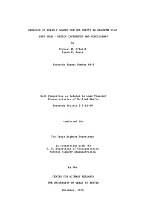
  • 43. ~l or = . . . . . . • • . • . . . (13.5) whichever gives the smaller value. Since gross base settlement at a given percentage of ultimate capacity appears to be directly proportional to base diameter, consideration should be given to providing factors of safety for the base load of greater than 3 in the second expression for very large-diameter bells. For bells with a diameter of less than nine feet, a factor of safety of 3 is appropriate to control initial settlement. As can be observed from Fig. 12.68, when the base diameter is 15 feet, a factor of safety of 4 will be required to limit gross settlement to 0.5 inches. Thus, for bells with diameters between 9 and 15 feet, the factor of safety should be determined by linear interpolation. Calculation of Settlement !! Design Load After the design load has been established considering failure in plunging, it is advisable to check the settlement of the butt of the shaft. An approximate method for making a check on the immediate settlement for shafts in Beaumont Clay is to use dimensionless load-settlement graphs developed from load tests, such as the graphs shown in Figs. 12.66 and 12.68. Average relationships from those figures for use in making design estimates for immediate settlement of shafts are given in Figs. 13.1 and 13.2. The applicability of Figs. 13.1 and 13.2 to soils with signifi- cantly different stress-strain properties from those of the soil at the SH225 site is unknown. Results from load tests of instrumented shafts
  • 44. 1.0 V- I0.8 I~ c:r w 0.6a.. -(/) a -~ 0.4 a 0.2 o.o ____~____~____~____~____~____~____~__~ 0.0 0.1 0.2 0.3 0.4 0.5 0.6 0.7 0.8 MEAN SETTLEMENT (in.) Fig. 13.1. Design Curve for Side Load Versus Settlement for Drilled Shafts in Beaumont Clay
  • 45. 1.0 r------r------,-----~:::s:::::=_---___., 0.8~--------~------~£-~--------~--------~ !J -= 0.6~----------+-~--------~----------~----------~ r:D CJ - "-r:D 0.4~------~--~-----------4------------~-----------; CJ 0.2~~L------+----------4---------~~--------~ O.OL-________-L__________~________~________~ 0.0 1.0 2.0 BASE SETTLEMENT BASE DIAMETER 3.0 Fig. 13.2. Design Curve for Base Load Versus Settlement for Drilled Shafts in Beaumont Clay 4.0
  • 46. 544 in other soils are necessary before such settlement graphs can be generalized. The use of Figs. 13.1 and 13.2 is illustrated in the example design problems which follow. Although not usually required for design, more precise estimates of immediate settlement can be made for applied load corresponding to the design load or to any other value of applied load by employing one of the methods of behavioral synthesis described in Chapter III. For example, the load transfer curves obtained in the SH225 tests could be categorized according to soil type, position on shaft, and method of construction, and generalized to apply to all shafts of similar diameter installed in Beaumont Clay. These empirical curves could then be used as input to computational schemes, such as those described by Coyle and Reese (1966) and Vijayvergiya, Hudson, and Reese (1969), to model the behavior of a given shaft pursuant to design. If necessary, long-term consolidation settlement can be estimated by using the technique outlined in Chapter IV. Concrete It appears that the concrete specified for drilled shaft construction, particularly where temporary casing is to be used, should have a minimum slump of six inches, with a water-cement ratio of 0.6 by weight. The customary slump presently employed is three to four inches. Furthermore, the maximum coarse aggregate size should be limited to one inch when temporary casing and drilling mud are to be used in order to give the greatest assurance that concrete can flow upward between the casing and sides of the borehole to displace the maximum amount of drilling mud.
  • 47. ~5 Example Design Problems Two example problems are now presented to illustrate the suggested design procedures. Example Problem li£. 1. I. Field Conditions. A 36-inch-diameter straight shaft is to be installed in the Beaumont Clay at a site where the soil consists of layered stiff clay and clayey silt. Stiff clay is present from the ground surface, elevation +50 feet, to elevation +30 feet. Clayey silt is present from elevation +30 feet to elevation +25 feet. Stiff clay is again encountered from elevation +25 feet to elevation -20 feet. The shaft is to be terminated at elevation 0 feet. Exploration has indicated that the clayey silt zone is unstable. It will probably be necessary to process the hole from the surface to an elevation of +20 feet, after which the mud will be bailed out. The remaining segment (elevation +20 feet to elevation 0 feet) will be drilled in the dry. Undisturbed samples have been recovered from the upper and lower clay strata, but only T.H.D. penetrometer soundings are available from the clayey silt layer. The shear strength in the top clay layer is constant at 1.0 tsf and the shear strength in the lower clay layer is constant at 2.0 tsf. The T.H.D. penetrometer yielded an average of 15 blows per foot in the clayey silt layer. II. Requirement. It is required to compute the working load on the shaft such that minimum factors of safety of 2.5 against total plunging failure and 3.0 against base failure are achieved.
  • 48. 546 III. Solution. It is necessary to compute the side capacity by an incremental procedure, as outlined below. The solution for side capacity is illustrated in Fig. 13.3. A. Design Category: A.2. B. Values of Design Parameters 1. Elevation +50 to +30 ex = 0.3avg 2. Elevation +30 to +25 p = 60 3. Elevation +25 to +20 4. ex =avg Elevation +20 to 0 ex = avg N = 9 c 0.3; 0.5; limi ting side shear stress of 0.4 tsf. limiting side shear stress of 0.9 tsf. C. Values of Unit Side Shear Capacities 1. Elevation +50 to +30 (qS)ult = 0.3(1.0) = 0.30 tsf 2. Elevation +30 to +25 (qS)ult = 3. Elevation +25 to +20 = 4. Elevation +20 to 0 15 60 = 0.25 tsf 0.3(2.0) = 0.6 tsf > 0.4 tsf; use 0.4 tsf (qS)ult = 0.5(2.0) = 1.0 tsf > 0.9 tsf; use 0.9 tsf
  • 49. Elevation +50 Ground Surface m IQ '" STIFF CLAY CLAYEY SILT STIFF CLAY Fig. 13.3. o Shear Strength. tsf 1 0 2 0 15 Blow. per Foot. T.H.D. Cone Penetrometer Dedgn Parameter err • 0.3 aVI p • 60 Limiting Side Shear. 0.4 taf Limiting Side Shear • 0.9 tsf Unit Effective Side Shear Peripheral Capacity Area (tlf) (sq. ft.) 0.3 132 0.25 47 0.4 47 0.9 132 TalAL Side Capacity for Design Example Problem No. 1 Ultimate Side Capacity (tons) 39.6 11.8 18.8 118.7 189
  • 50. 548 D. Ultimate Side Capacity 1. Elevation +50 to +30 Effective length = 20 feet less top two diameters (6 feet), or 14 feet Peripheral area = 3n = 9.42 square feet per linear foot (QS) ul t = (9.42)(14)(0.30) = 39.6 tons 2. Elevation +30 to +25 (Qs) ult = (9.42) (5) (0.25) = 11.8 tons 3. Elevation +25 to +20 (QS) ul t = (9.42) (5) (0.4) = 18.8 tons 4. Elevation +20 to 0 Effective length = 20 feet less bottom two diameters (6 feet), or 14 feet (QS)ult = (9.42)(14)(0.9) = 5. Total Ultimate Side Capacity E. Ultimate Base Capacity: (QB)ult = 9(0.785)(3)2(2.0) = F. Ultimate Shaft Capacity = G. Design Load Based Upon Total Factor of Safety of 2.5 316 126 tons= 2.5 = H. Design Load Based Upon Side Factor of Safety of 1 and Base Factor of Safety of 3 189 + 127 = 231 tons > 126 tons 3= I. Use Design Load Based Upon Total Factor of Safety of 2.5, or 126 tons 118. 7 tons 189 tons 127 tons 316 tons
  • 51. 549 J. Check Approximate Immediate Settlement From Figs. 13.1 and 13.2 1. Using trial and error procedure, assume immediate butt settlement is 0.05 inches. Also assume butt settlement equals mean shaft settlement (shaft incompressible). From Fig. 13.1, mean settle- ment of 0.05 inches produces 75 per cent of maxi- mum side resistance, or 0.75 (189) = 142 tons. Assuming base settlement equals butt settlement, Base settlement Base diameter = 0.05 = 0.14 X 10⁻² 36 or according to Fig. 13.2, about 10 per cent of the ultimate base load will be developed (13 tons). The approximate butt load corresponding to a butt settlement of 0.05 inches is, then, 142 + 13 = 155 tons> 126 tons. Try a smaller settlement. 2. Using the same method as in Step 1, assume butt settlement = 0.03 inches. From Fig. 13.1, 62 per cent of maximum side resistance will be devel- oped (117 tons). From Fig. 13.2, 6 per cent of maximum base reSistance will be developed (8 tons). The butt load corresponding to an immediate butt settlement of 0.03 inches is 117 + 8 = 125 ~ 126 tons. Therefore, the estimated immediate butt settlement at design load is 0.03 inches.
  • 52. 550 Example Problem No. ~. I. Field Conditions. A belled shaft is to be installed in stiff clay at a site in the Beaumont Clay formation at which all boring and belling operations are to be accomplished in the dry. The stem is to be 30 inches in diameter, extending from the ground surface, elevation +25 feet, to -5 feet. The bell will have a base diameter of 90 inches, and the base will be set at an elevation of -9.5 feet. Laboratory testing indicated that the shear strength of the stiff clay soil varies linearly from 0.6 tsf at the surface to 2.6 tsf at an elevation of -15 feet. The stiff clay is underlain by a silty layer from -15 feet to -25 feet having a shear strength of 0.7 tsf. II. Requirement. It is required to compute the working load on the shaft such that minimum factors of safety of 2.5 against total plunging failure and 3.0 against base failure are achieved. III. Solution. It is necessary to compute the side capacity by an incremental procedure. The solution for side capacity is illustrated in Fig. 13.4. A. Design Category: B.l. B. Depth at which maximum allowable shear stress is reached 1. Allowable side shear stress = (0.3)S or 0.4 tsf 2. Elevation at which (0.3)S = 0.4 tsf is +10.4 feet 3. Therefore, take increments as +25 to +10.4 and +10.4 to -5. C. Values of Design Parameters
  • 53. Elevation +2 +15 +5 -5 -15 -25 i Io ..........." ........ .:1 l T Cround Surface Um/11 STIFF CLAY SILT o : : I; I: Ii. I ':. I i Shear Strength, taf 1.0 2.0 1 ,,--0.3 x 1 '; (Shear 1 Strength) I . ~Limit1ng Slde I ~. Shear - 0.4 tsf Unlt Design Side Shear Parameter Capacity 3.0 (taf) 11' avg - 0.3 0.33 Limiting Side 0.4 Shear - 0.4 tat Fig. 13.4. Side Capacity for DeSign Example Problem No. 2 Bffective Ultimate Peripheral Side Area Capacity (aq. ft.) (t-> 75.3 24.S 81.5 32.6 TOTAL 57.4
  • 54. 552 1. Elevation +25 to +10.4 a = 0.3 avg 2. Elevation +10.4 to -9.5 Limiting side shear stress = 0.4 tsf N ::: 9 c D. Values of Unit Side Shear Capacities 1. Elevation +25 to +10.4 ( ) 0 3 0.85 + 1.33 qs ul t =. 2 2. Elevation +10.4 to -5 (q ) - 0.4 tsfSuIt - E. Ultimate Side Capacity 1. Elevation +25 to +10.4 Effective length = 9.6 feet = 0.33 tsf Peripheral area = 2.5~ = 7.85 square feet per linear foot (Qs)uit = (7.85)(9.6)(0.33) = 24.8 tons 2. Elevation +10.4 to -5 Effective length = 10.4 feet (QS)u1t = (7.85)(10.4)(0.4) = 32.6 tons 3. Total Ultimate Side Capacity 57.4 tons F. Ultimate Base Capacity 1. Average shear strength for two base diameters (15 feet) beneath base = ~2.442~5.52 + ~0.72~9.il = 1. 34 tsf 15 2. (QB)u1t = 9(0.785)(7.5)2(1.34) = 533 tons
  • 55. G. Ultimate Shaft Capacity = H. Design Load Based Upon Total Factor of Safety of 2.5 590 = --- =2.5 I. Design Load Based Upon Base Factor of Safety of 3 and Side Factor of Safety of 1 = 5;3 + 57.4 = 235 tons < 236 tons J. Use Design Load of 235 tons K. Settlement check: 553 590 tons 236 tons Following the procedure outlined in Example Problem No.1, the indicated immediate settlement is about 0.5 inches. This value may be somewhat low because of the thick layer of silty soil present beneath the base. Implementation of Design Procedures The implementation by the Texas Highway Department of the suggested design procedures would represent a step toward more economical design for drilled shafts. Since the real factors of safety for shafts designed using these procedures would be less than those on shafts installed under present design methods, inspection of the installation of drilled shafts, therefore, should be conducted with added care.
  • 56. CHAPTER XIV CONCLUSIONS AND RECOMMENDATIONS Based upon the results of the load tests of the four instrumented test shafts at the SH225 site, several conclusions concerning the behavior of axially loaded drilled shafts in Beaumont Clay have been drawn. Those conclusions, elaborated upon in previous chapters, are enumerated concisely below. 1. Floating drilled shafts resist an appreciable portion of the applied load in side friction. 2. The side resistance was found to vary with depth, becoming smaller near the top and bottom of the shaft. The reduced side resistance near the top appeared to be caused by drying of the soil surrounding the top of the stem which reduced lateral pressure between the soil and the concrete shaft. The reduced load transfer near the base appeared to be the result of increased wetting of the soil immediately adjacent to the concrete near the bottom of the stem and to mechanical base-side interference. 3, The maximum shear stress developed at or near the shaft- soil interface was less than the shear strength of the soil. This diminished shear capacity appeared to be the combined result of softening of the soil immediately adjacent to the shaft due to migration of excess water from the concrete, of surface and base effects, of shear strength reduction 554
  • 57. 555 due to remolding the soil along the borehole walls and opening of fissures during boring operations, and of drilling mud trapped between the concrete and soil when the shaft is installed in a processed hole. 4. Except for small mechanical base-side interaction differ- ences, shaft geometry had no influence on behavior during initial loading. The belled shaft exhibited a greatly reduced side capacity upon delayed reloading, possibly reflecting the fact that the displacement required to mobi- lize the full capacity of that shaft was large in compari- son to the displacement required to mobilize the full capacity of the straight shafts, thereby causing the strength of the soil along the sides to be greatly reduced. - 5. The use of the wet process to install Test Shaft No. 4 caused a significant decrease in average side capacity, primarily because drilling mud was trapped between the concrete shaft and the soil and because some of the concrete at the soil- shaft interface was of very poor quality. That part of Test Shaft No. 4 drilled dry (bottom five feet) developed a side resistance comparable to that of the other three test shafts, which had been installed entirely in the dry. 6. The bearing capacity of the base can be estimated reliably from the usual bearing capacity theory for clay, using the average strength for two base diameters beneath the base as the appropriate value for undrained cohesion in the bearing capacity equation.
  • 58. 7. The instrumentation of drilled shafts to measure load distribution was shown to be feasible. The Mustran system proved to be an outstanding instrumentation scheme. The concrete embedment gages, when wired in full bridge con- figuration in the "improved tee," performed well, except that load resolution was not as good as with Mustran cells. The bottomho1e cell performed adequately, as did the weld- able gages (except for rather low resolution). The tell- tales did not yield acceptable results. The hydraulic pressure cell also gave poor results. 8. The method of top-level, in-shaft calibration is adequate for shafts installed in the dry. Processed shafts, or those with otherwise irregular sides, are best calibrated by excavating soil from around the stem and reloading the shaft to obtain direct load-reading curves for gages in the freestanding portion. 9. Perhaps the greatest uncertainty related to the design of drilled shafts in Beaumont Clay is the adequate estimation of in situ soil properties. Shear strength profiles deter- mined by six different methods exhibited considerable variation. Those given by the T.R.D. cone penetrometer and the transmatic triaxial test had the most conservative values for shear strength. The variation in indicated shear strength reflects sampling disturbance and differ- ences in testing techniques, and it attests to the need for the development of better in situ strength measurement. 556
  • 59. 10. When the soil is fissured, considerable scatter in indicated shear strength exists. The mean profile is an appropriate representation of the soil strength as a function of depth, and side and base capacities may be computed from such a profile. The following recommendations are made concerning the research reported herein. 1. The design procedure outlined in Chapter XIII should be incorporated as a tentative method for sizing drilled shafts in Beaumont Clay. If that procedure is implemented, parti- cular attention should be paid to careful inspection during installation and to obtaining serviceability records for shafts designed by the new procedure. 2. Several of the categories of design listed in Chapter XIII remain inadequately investigated, requiring that values of design parameters be quite conservative. Therefore, it is important that long-term tests be conducted, particularly on belled shafts, to determine the effects of sustained loading on side capacity. Further investigations on the effect of varying the method of installing a shaft with the aid of drilling mud should also be made. These investiga- tions would increase the confidence in the recommended values for shear strength reduction factors for processed shafts and would hopefully lead to an installation procedure whereby drilling mud can be consistently expelled completely from the borehole. 557
  • 60. 558 3. Testing of drilled shafts should be extended to other soil formations in order to develop general design procedures which can be used confidently at any location. Test shafts in such studies must be instrumented, and tests must be conducted to plunging failure in order to advance the state of the art. Mere proof testing, in which the test shaft is not failed, should be avoided when possible.
  • 61. REFERENCES A1-Lay1a, M. T. H. (1970), Study of Certain Geotechnical Properties 2! Beaumont Clay, thesis presented to Texas A&M University, at College Station, Texas, in 1970, in partial fulfillment of the requirements for the degree of Doctor of Philosophy. American Concrete Institute (1963), "Recommended Practices for Concrete Formwork," Standards, American Concrete Institute, 1963, pp. 347-363. American Railway Engineering Association (1950), "Steel and Timber Pile Tests - West Atchafa1aya F100dway - New Orleans, Texas and Mexico Railway," A.R.E.A. Bulletin, Vol. 52, No. 489, September - October, 1950. American Society for Testing and Materials (1970), 1970 Book of A.S.T.M. Standards, Part 11, April, 1970. Aschenbrenner, R. (1967), "Three-Dimensional Analysis of Pile Foundations," Journal of the Structural Division, A.S.C.E., Vol. 93, No. ST1, February-,-1967. Baker, C. N., Jr., and Kahn, F. (1969), "Caisson Construction Problems and Methods of Correction," Paper presented to 1969 A,S,C,E, Annual Meeting, Chicago, Illinois, Meeting Preprint No. 1020, October, 1969. Barden, L., and Monckton, M. F. (1970), "Tests on Model Pile Groups in Soft and Stiff Clay," Geotechnique, Vol. XX, No.1, London, March, 1970. Barker, W. R., and Reese, L. C. (1969), Instrumentation for Measurement of Axial Load in Drilled Shafts, Research Report 89-6, Center for Highway Research, The University of Texas at Austin, Austin, Texas, November, 1969. Barker, W. R., and Reese, L. C. (1970), Load-Carrying Characteristics of Drilled Shafts Constructed with the ~ of Drilling Fluids, Research Report 89-9, Center for Highway Research, The University of Texas at Austin, Austin, Texas, 1970. Bernard, H. A., LeBlanc, R. J., and Major, C. F. (1962), "Recent and Pleistocene Geology of Southeast Texas,lI Geology of the ~ Coast and Central Texas, Houston Geological Society, Houston, Texas, 1962, pp. 175-224. Bhanot, K. L. (1968), Behaviour of Scaled and Full-Length Cast-in-P1ace Concrete Piles, thesis presented to The University of Alberta, at Edmonton, Alberta, in 1968, in partial fulfillment of the require- ments for the degree of Doctor of Philosophy. 559
  • 62. 560 Brooker, E. W., and Ireland, H. O. (1965), "Earth Pressures at Rest Related to Stress History," Canadian Geotechnical Journal, Vol. II, No.1, February, 1965. Burland, J. B. (1963), Discussion in Grouts and Drilling Muds in Engineer- ing Practice, Butterworths, London, 1963, pp. 223-225. Burland, J. B., Butler, F. G., and Dunican, p. (1966), "The Behaviour and Design of Large Diameter Bored Piles in Stiff Clay," Proceedings of the Symposium ~ Large Bored Piles, Institution of Civil Engineers, London, February, 1966. Cambefort, H. (1953), "Le Comportement Des Pieux For~s Et Les Essais De P~n~tration," Proceedings of the Third International Conference on Soil Mechanics ~ Foundation Engineering, 1953. Campbell, D. B., and Hudson, W. R. (1969), The Determination of Soil --- -- ----Properties ~ Situ, Research Report 89-7, Center for Highway Research, The University of Texas at Austin, Austin, Texas, November, 1969. Carson, A. B. (1965), Foundation Construction, McGraw-Hill, New York, 1965. Chadeisson, R. (1961), "Influence Du Mode De Perforation Sur Le Comporte- 'ment Des Pieux Fores Et Moul~s Dans Le Sol," Proceedings of the Fifth International Conference ~ Soil Mechanics and Foundation Engineering, 1961. Chandler, R. J. (1968), "The Shaft Friction of Piles in Cohesive Soils in Terms of Effective Stress," Civil Engineering and Public Works Review, London, January, 1968. Chellis, R. D. (1961), Pile Foundations, Second Edition, McGraw-Hill, New York, 1961. Chuang, J. W., and Reese, L. C. (1969), Studies of Shearing Resistance Between Cement Mortar ~ Soil, Research Report 89-3, Center for Highway Research, The University of Texas at Austin, Austin, Texas, May, 1969. Collins, L. E. (1953), "A Preliminary Theory for the Design of Under- reamed Piles," Transactions of South African Institution of Civil Engineers, Vol. 3, No. 11, Pretoria, 1953. Coyle, H. M., and Reese, L. C. (1966), "Load Transfer for Axially Loaded Piles in Clay," Journal of the Soil Mechanics and Foundations Division, A.S.C.E., Vo1.92:-N'0. SM2, March, 1966. Crandall, L. L. (1948), "Electrical Resistance Strain Gauges for Deter- mining the Transfer of Load from Driven Piling to Soil," Proceedings of the Second International Conference on Soil Mechanics and Foun- dation Engineering, 1948.
  • 63. 561 Cummings, A. E. (1949), "Lectures on Foundation Engineering," University of Illinois Bu1 Vol. 47, No. 35, Urbana, Illinois, December, 1949. D'Appo10nia, E., and Steel H-Pi1es," sion, A.S.C.E., Romua1di, A. M. (1963), "Load Transfer in End-Bearing Journal of the Soil Mechanics and Foundations Divi-.;:;...;;;..;;;,;;;.=.;;;. - - - - - - =~==.;;.~ Vol. 89, No. SM2, March, 1963. Davisson, M. T., and Salley, J. R. (1969), IILatera1 Load Tests on Drilled Piers," Performance of Deep Foundations, A.S.T.M. S.T.P. American Society for Testing and Materials, 1969. Deb, A. K., and Chandra, S. (1964), "Short Bored Piles for Foundations in Expansive Clays," Proceedings of the Symposium .£!! Bearing Capacity of Piles, Central Building Research Institute, Roorkee, India, 1964. Foundation Engineering, State of the Art Volume, 1969. DuBose, L. A. (1955), "Load Studies of Drilled Shafts,1I Proceedings, Highway Board, Vol. 34, Washington, D. C., 1955. DuBose, L. A. (1956), ~ Comprehensive Study of Factors Influencing the Load Carrying Capacities of Drilled and Cast-in-P1ace Concrete Piles, Texas Transportation Institute, A&M College of Texas, College Station, Texas, 1956. Ehlers, C. J., Reese, L. C., and Anagnos, J. N. (1969), ~ Nuclear Method of Soil-Moisture Determination at Depth, Research Report 89-4, Center for Highway Research, The University of Texas at Austin, Austin, Texas, June, 1969. Ellison, R. D. (1968), An Analytical Study of the Mechanics of Single Pile Foundations, thesis presented to Carnegie-Mellon University, at Pittsburgh, Pennsylvania, in 1968, in partial fulfillment of the requirements for the degree of Doctor of Philosophy. Evans, L. T. (1952), The Drilled Pile, Edwards Brothers, Ann Arbor, Michigan, 1952. Fernandez-Renau, L. (1965), Discussion in Proceedings of the Sixth International Conference .£!! Soil Mechanics and Foundation Engineering, Vol. III, 1965, pp. 495-496. Fleming, W. G. K., and Salter, T. H. (1962), "Reports on Loading Tests on a Large Diameter Underreamed Bored Pile," Civil Engineering and Public Works Review, London, October, 1962.
  • 64. 562 Frischmann, W. W., and Fleming, W. G. K. (1962), "The Use and Behaviour of Large Diameter Piles in London Clay," The Structural Engineer, London, April, 1962. Fuller, F. M., and Hoy, H. E. (1970), "Pile Load Tests Including Quick Load Test Method, Conventional Methods, and Interpretations," Paper presented to National Meeting, Highway Research Board, Washington, D. C., January, 1970. Geddes, J. D. (1966), "Stresses in Foundation Soils Due to Subsurface Loading," Geotechnique, Vol. XVI, No.3, London, September, 1966. Geddes, J. D. (1969), "Boussinesq-Based Approximations to the Vertical Stresses Caused by Pile-Type Subsurface Loadings," Geotechnique, Vol. XIX, No.4, London, December, 1969. Glossop, R. and Greeves, I. s. (1946), "A New Form of Bored Pile," Concrete and Constructional Engineering, London, December, 1946. Gnaedinger, J. P. (1964), Discussion in Proceedings, Conference on Deep Foundations, Vol. II, Mexican Society of Soil Mechanics, Mexico City, 1964, pp. 625-627. Golder, H. Q., and Leonard, M. W. (1954), "Some Tests on Bored Piles in London Clay," Geotechnique, Vol. IV, No.1, London, March, 1954. Green, H. (1961), "Long-Term Loading of Short Bored Piles," Geotechnique, Vol. XI, No.1, London, March, 1961. Greer, D. M. (1969), "Drilled Piers State of the Art, 1969," W.C.A. Geotechnical Bulletin, Vol. III, No.2, Woodward-Clyde and Associates, New York, September, 1969. Hansen, V., and Kneas, F. N. (1942), "Static Load Tests for Bearing Piles,11 Civil Engineering, A.S.C.E., Vol. 12, No. 10, October, 1942. Harris, F. A. (1951), "Plum Creek Load Test Results, Progress Report No. 2 on Skin Friction Investigation,11 Texas Highway Department, Houston Urban Expressways Office, May, 1951. Hobbs, N. B. (1963), "An Analytical Approach to the Bearing Capacity and Settlement 0 f the Large Diameter Bored Pile," Proceedings 0 f Institution of Civil Engineers, Vol. 25, London, 1963, Paper No. 6616. Horner, J. M. (1969), Uplift Resistance of Straight Auger and Belled Auger Footings in Sandy Silt, United States Department of the Interior, Bureau of Reclamation, Denver, Colorado, November, 1969.
  • 65. 563 Housel, W. S. (1969), "Design of Caissons on Granular-Cohesive Soils," Performance £i Deep Foundations, A.S.T,M. S,T.P. 444, American Society for Testing and Materials, 1969. Janbu, N., Bjerrum, L., and Kjaernsli (1956), "Soil Mechanics Applied to Some Engineering Problems," (in Norwegian), Norwegian Geotechnical Institute Bulletin No. ~, Oslo, 1956, Kerisel, J. L. (1964), "Deep Foundations - Basic Experimental Facts," Proceedings, Conference on Deep Foundations, Mexican Society of Soil Mechanics, Vol. I, Mexico City, 1964. Kerisel, J. L. (1967), "Vertical and Horizontal Bearing Capacity of Deep Foundations in Clay," Proceedings, Symposium..22. Bearing Capacity and Settlement of Foundations, Duke University, Durham, North Carolina, 1967. Komornik, A., and Wiseman, G. (1967), "Experience with Large Diameter Cast-in-Situ Piling," Proceedings, Third Asian Regional Conference ~ Soil Mechanics and Foundation Engineering, Jerusalem Academic Press, Jerusalem, 1967. Lambe, T. W., and Whitman, R. V. (1969), Soil Mechanics, Wiley, New York, 1969. Leonards, G, A. (1962), "Engineering Properties of Soils," Foundation Engineering, ed. by G. A. Leonards, McGraw-Hill, New York, 1962, Lysmer, J., and Duncan, J. M. (1969), Stresses and Deflections in Foundations and Pavements, Fourth Edition, Department of Civil Engineering, Institute of Transportation and Traffic Engineering, University of California, Berkeley, California, 1969. Martins, J. B. (1963), "Pile Load Tests on the River Pungu~," Proceedings, Third Regional Conference for Africa on Soil Mechanics and Foundation Engineering, The Rhodesian Institution of Engineers, Salisbury, 1963. Matich, M. A. J., and Kozicki, P. (1967), "Some Load Tests on Drilled Cast-in-Place Concrete Caissons," Canadian Geotechnical Journal, Vol. IV, No.4, November, 1967. Matlock, H., and Reese, L. C. (1962), "Generalized Solutions for Laterally Loaded Piles," Transactions, A,S,C,E., Vol. 127, Part I, 1962. Mattes, N. S., and Poulos, H, G, (1969), "Settlement of Single Compressible Pile," Journal of the Soil Mechanics and Foundations Division, A,S,C,E., Vol. 95, No, SMl, January, 1969. McClelland, B., Focht, J. A., Jr., and Emrich, W. J. (1969), "Problems in Design and Installation of Offshore Piles," Journal of the Soil Mechanics and Foundations Division, A.S.C,E" Vol. 95, No. SM6, November, 1969.
  • 66. 564 Meyerhof, G. G. (1951), "The Ultimate Bearing Capacity of Foundations," Geotechnique, Vol. II, No.4, London, December, 1951. Meyerhof, G. G., and Adams, J. I. (1968), "The Ultimate Uplift Capacity of Foundations," Canadian Geotechnical Journal, Vol. V, No.4, November, 1968. Meyerhof, G. G., and Murdock, L. J, (1953), "An Investigation of the Bearing Capacity of Some Bored and Driven Piles in London Clay," Geotechnique, Vol. III, No, 7, London, September, 1953. Mindlin, R.D. (1936), "Force at a Point in the Interior of a Semi- Infinite Solid," Physics, Vol. 7, May, 1936. Mohan, D., and Chandra, S. (1961), ItFrictiona1 Resistance of Bored Piles in Expansive Clays," Geotechnique, Vol. XI, No.4, London, December, 1961. Mohan, D., and Jain, G. S. (1961), "Bearing Capacity of Bored Piles in Expansive Clays," Proceedings of the Fifth International Conference ~ Soil Mechanics and Foundation Engineering, 1961. Mohan, D., Jain, G. S., and Jain, M. P. (1967), "A New Approach to Load Tests," Geotechnigue, Vol. XVII, No.3, London, September, 1967. Mohan, D., Murthy, V. N. S., and Jain, G. S. (1969), "Design and Construction of Mu1ti-Under-Reamed Piles," Proceedings of the Seventh International Conference on Soil Mechanics and Foundation --- --Engineering, 1969. Moorhouse, D. C., and Sheehan, J. v. (1968), "Predicting Safe Capacity of Pile Groups," Civil Engineering, A.S.C.E., Vol. 38, No. 10, October, 1968. Nair, K. (1967), "Load Settlement and Load Transfer Characteristics of a Friction Pile Subject to a Vertical Load," Proceedings, Third Pan American Conference ~ Soil Mechanics and Foundation Engineering, Vol. I, Venezuela, 1967. Nair, K., Gray, H., and Donovan, N. c. (1969), "Analysis of Pile Group Behavior," Performance of Deep Foundations, A.S.T.M. S.T.P. 444, American Society for Testing and Materials, 1969. Neville, A. M. (1963), Properties of Concrete, Wiley, New York, 1963. Osgerby, C., and Taylor, P. T. (1968), "Vibrating Wire Load Cell," Experimental Mechanics, Vol. 8, No.9, September, 1968.
  • 67. 565 Osterberg, J. o. (1968), "Drilled Caissons - Design, Installation, Application," Chicago Soil Mechanics Lectures - 1968, Northwestern University, Evanston, Illinois, 1968. Palmer, D. J., and Holland, G. R. (1966), "The Construction of Large Diameter Bored Piles with Particular Reference to London Clay," Proceedings of the Symposium on Large Bored Piles, Institution of Civil Engineers, London, February, 1966. Pandey, V. J. (1967), "Some Experiences with Bored Piling," Journal of the Soil Mechanics and Foundations Division, A.S.C.E. , Vol. 93, No. SM5, September, 1967, Part 1. Peck, R. B. (1965), "Pile and Pier Foundations," Journal of the Soil Mechanics and Foundations Division, A.S.C.E., Vol. 9~ No. SM2, March, 1965. Peck, R. B., Hanson, W. E., and Thornburn, T. H. (1953), Foundation Engineering, Wiley, New York, 1953. Potyondy, J. G. (1961), "Skin Friction Between Various Soils and Construction Materials," Geotechnique, Vol. XI, No.4, London, December, 1961. Poulos, H. G. (1968), "Analysis of the Settlement of Pile Groups," Geotechnique, Vol. XVIII, No.4, London, December, 1968. Reese, L. C., Brown, J. C., and Dalrymple, H. H. (1968), Instrumentation for Measurements of Lateral Earth Pressure in Drilled Shafts, Research Report 89-2, Center for Highway Research, The University of Texas at Austin, Austin, Texas, September, 1968. Reese, L. C., and Hudson, W. R. (1968), Field Testing of Drilled Shafts to Develop Design Methods, Research Report 89-1, Center for Highway Research, The University of Texas at Austin, Austin, Texas, April, 1968. Reese, L. C., Hudson, W. R., and Vijayvergiya, V. N. (1969), "An Investigation of the Interaction Between Bored Piles and Soil," Proceedings of the Seventh International Conference ~ Soil Mechanics and Foundation Engineering, 1969. Reese, L. C., O'Neill, M. W., and Smith, R. E. (1970), "Generalized Analysis of Pile Foundations," Journal of the Soil Mechanics and Foundations Division, A.S.C.E., Vol. 96, No. SM1, January, 1970. Robinsky, E.!., and Morrison, C. F. (1964), "Sand Displacement and Compaction Around Model Friction Piles," Canadian Geotechnical Journal, Vol. I, No.2, March, 1964.
  • 68. 566 Salas, J. A. J., and Be1zunce, J. A. (1965), "R~solution Th~orique De La Distribution Des Forces Dans Des Pieux," Proceedings of ~ Sixth International Conference ~ Soil Mechanics and Foundation Engineering. 1965. Saul, W. E. (1968), "Static and Dynamic Analysis of Pile Foundations," Journal of the Structural Division. A.S.C.E., Vol. 94, No. ST5. May, 1968. Schlitt, H. G. (1952). "Group Pile Load Tests in Plastic Soils." Proceedings, Highway Research Board. Vol. 31. Washington. D. C., 1952. Seed, H. B., and Reese. L. C. (1957). "The Action of Soft Clay Along Friction Piles." Transactions. A.S.C.E., Vol. 122. 1957. Seed. H. B.• and Reese, L. C. (1964). "Predicting the Performance of Fric tion Piles in Saturated Clays." Proceedings, Conference £E. Deep Foundations. Mexican Society of Soil MechaniCS, Vol. I, Mexico City. 1964. Sellards, E. H., Adkins, W. S., and Plummer, F. B. (1932), The Geology of Texas, Volume 1. Stratigraphy, Bureau of Economic Geology, The University of Texas at Austin. Austin, Texas, August. 1932. Skempton. A. W. (1951), "The Bearing Capacity of Clays." Proceedings of The Building Research Congress. 1951, Division I. Building Research Congress. London, 1951. Skempton. A. w. (1959). "Cast-in-Situ Bored Piles in London Clay," Geotechnique, Vol. IX, No.4, London, December, 1959. Skempton. A. W.• and Hutchinson. J. (1969), "Stability of Natural Slopes and Embankment Foundations," Proceedings of the Seventh International Conference £E. Soil Mechanics and Foundation Engineering, State of the Art Volume, 1969. Skipp, B. D. (1966), Discussion in Proceedings of the Symposium on Large Bored Piles, Institution of Civil Engineers, London. February, 1966. pp. 146-147. Snow. R. (1965), "Telltales," Foundation Facts, Vol. 1, No.2, Raymond International, New York, Fall, 1965. Sowers, G. B., and Sowers. G. F. (1961), Introductory Soil Mechanics and Foundations, Second Edition, MacMillan. New York, 1961. Sowers, G. F. (1962), "Shallow Foundations. II Foundat ion Engineering, ed. by G. A. Leonards, MCGraw-Hill, New York, 1962.
  • 69. 567 Taylor, D. W. (1948), Fundamentals of Soil Mechanics, Wiley, New York, 1948. Terzaghi, K. (1943), Theoretical Soil Mechanics, Wiley, New York, 1943. Texas Highway Department (1962), Standard Specifications for Road and Bridge Construction, State Highway Department of Texas, Austin, Texas, January, 1962. Texas Highway Department (1964), Foundation Exploration and Design Manual, State Highway Department of Texas, Bridge Division, Austin, Texas, January, 1964. Texas Highway Department (1965), Special Provision to Item 405, Test Loading Piling, Standard Specifications for Road and Bridge Construc- tion, State Highway Department of Texas, Austin, Texas, July, 1965. Texas Transportation Institute (1965), Bibliography 65-10, Drilled Shafts, Texas Transportation Institute, Texas A&M University, College Station, Texas, 1965. Thurman, A. G., and D'Appo10nia, E. (1965), "Computed Movement of Friction and End-Bearing Piles Embedded in Uniform and Stratified Soils," Proceedings of the International Conference on Soil Mechanics and Foundation Engineering, 1965. Tomlinson, M. J. (1969), Foundation Design and Construction, Second Edition, Wi1ey-Interscience, New York, 1969. Trollope, D. H., Freeman, McD., and Peck, G. M. (1966), "Tasman Bridge Foundations," The Journal of the Institution Engineers, Australia, June, 1966. Turner, E. A. (1962), "Uplift Resistance of Transmission Tower Footings," Journal of the Power Division, A.S.C.E., Vol. 88, No. P02, July, 1962. U. S. Army Corps of Engineers (1965), Standard Practice for Concrete, Engineer Manual 1110-2-2000, Department of the Army, Washington, D. C., December, 1965. U. S. Army Engineer District, Fort Worth, Texas (1968), Investigation for Building Foundations in Expansive Clays, U. S. Army Corps of Engineers, Fort Worth, Texas, April, 1968. Van Doren, L. M., Hazard, S. G., Stallings, J. R., and Schnacke, D. P. (1967), Drilled Shaft Foundation Test Program for State Highway Commission of Kansas, Van Doren-Hazard-Sta11ings-Schnacke Engineers- Architects,-ropeka, Kansas, August, 1967. Van Sic1en, D. C. (1961), "Surface Geology in and Near Houston," Geology of Houston and Vicinity, Texas, Houston Geological Society, Houston, Texas, 1961.
  • 70. 568 Van Weele, A. F. (1957), "A Method of Separating the Bearing Capacity of a Test Pile into Skin-Friction and Point-Resistance," Proceedings of the Fourth International Conference on Soil Mechanics and Foundation Engineering, 1957. Vesi~, A. (1963), "Bearing Capacity of Deep Foundations in Sand," Highway Research Record No. 39, Highway Research Board, Washington, D. C., 1963. Vesi6, A. (1967), "Ultimate Loads and Settlements of Deep Foundations in Sand," Proceedings, Symposium £.!!. Bearing Capacity and Settlement of Foundations, Duke University, Durham, North Carolina, 1967. Vesic5, A. (1969), IIExperiments with Instrumented Pile Groups in Sand,1I Performance of Deep Foundations, A,S.T.M. S.T.P. 444, American Society for Testing and Materials, 1969. I Vesic, A. (1970), IITests on Instrumented Piles, Ogeechee River Site, II Journal of the Soil Mechanics and Foundations Division, A,S.C,E, Vol. 96, No. SM2, March, 1970. Vijayvergiya, V. N., Hudson, W. R., and Reese, L. C. (1969), Load Distribution for ~ Drilled Shaft in Clay Shale, Research Report No. 89-5, Center for Highway Research, The University of Texas at Austin, Austin, Texas, March, 1969. Ward, W. H., Samuels, S. G., and Butler, M. E. (1959), "Further Studies of the Properties of London Clay," Geotechnique, Vol. IX, No.2, London, June, 1959. Watt, W. G., Kurfurst, P. J., and Zeman, Z. p. (1969), "Comparison of Pile Load-Test-Skin-Friction Values and Laboratory Strength Tests," Canadian Geotechnical Journal, Vol. VI, No.3, August, 1969. Whitaker, T. (1957), "Experiments with Model Piles in Groups," Geotechnique, Vol. VII, No.4, London, December, 1957. Whitaker, T., and Cooke, R. W. (1961), "A New Approach to Pile Testing," Proceedings of the Fifth International Conference £.!!. Soil Mechanics and Foundation Engineering, 1961. Whitaker, T., and Cooke, R. W. (1966), "An Investigation of the Shaft and Base Resistance of Large Bored Piles in London Clay," Proceedings of the Symposium £.!!. Large Bored Piles, Institution of Civil Engineers, London, February, 1966. Whitaker, T., Cooke, R. W., and Clarke, G. W. (1962), "100 Ton Load Cell for Pile Loading Tests," Engineering, Vol. 194, No. 5040, London, November 23, 1962.
  • 71. 569 White, E. E. (1967), "Developments in Large Diameter Piles or Caissons in the United States, II Proceedings, Third Asian Regional Conference £!! Soil Mechanics and Foundation Engineering, Jerusalem Academic Press, Jerusalem, 1967. Williams, G. M. J., and Colman, R. B. (1965), "The Design of Piles and Cylinder Foundations in Stiff, Fissured Clay, II Proceedings of the Sixth International Conference on Soil Mechanics and Foundation -- ---- ------~- Engineering, 1965. Woodward, R. J., Lundgren, R., and Boitano, J. D., Jr. (1961), "Pile Loading Tests in Stiff Clay," Proceedings of the Fifth International Conference on Soil Mechanics and Foundation Engineering, 1961. Zienkiewicz, O. C. (1967), The Finite Element Method in Structural and Continuum Mechanics, McGraw-Hill, London, 1967.