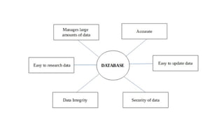
DBMS
Unit - 1
Why Database?
• A database is a collection of data, usually stored in electronic form. A
database is typically designed so that it is easy to store and access
information.
• A good database is crucial to any company or organisation. This is
because the database stores all the pertinent details about the
company such as employee records, transactional records, salary
details etc.
Manages large amounts of data
• A database stores and manages a large amount of data on a daily
basis. This would not be possible using any other tool such as a
spreadsheet as they would simply not work.
Accurate
• A database is pretty accurate as it has all sorts of build in constraints,
checks etc. This means that the information available in a database is
guaranteed to be correct in most cases.
Easy to update data
• In a database, it is easy to update data using various Data
Manipulation languages (DML) available. One of these languages is
SQL.
Security of data
• Databases have various methods to ensure security of data. There are
user logins required before accessing a database and various access
specifiers. These allow only authorised users to access the database.
Data integrity
• This is ensured in databases by using various constraints for data.
Data integrity in databases makes sure that the data is accurate and
consistent in a database.
Easy to research data
• It is very easy to access and research data in a database. This is done
using Data Query Languages (DQL) which allow searching of any data
in the database and performing computations on it.
Characteristics of Data in a Database
• The data in a database should have the following features:
1. Shared:
• Data should be sharable among different users and applications.
2. Persistence:
• Data should exist permanently in the database. Changes in the
database must not be lost because of any failure.
3. Validity/Integrity/Correctness:
• It should maintain integrity so that there is always correct data in the
database.
4. Security:
• Data should be protected from unauthorized access.
5. Non-redundancy:
• Data should not be repeated.
6. Consistency:
• A consistent state of the database satisfies all the constraints specified
in the database. Data in a database is consistent if any changes in the
database take the database from one consistent state to another.
7. Independence:
• The three levels in the schema should be independent of each other
so that the changes in the schema at one level should not affect the
other levels.
What is DBMS (Database Management
System)?
• Database Management System (DBMS) is a software for storing and
retrieving users’ data while considering appropriate security measures.
• It consists of a group of programs which manipulate the database. The
DBMS accepts the request for data from an application and instructs
the operating system to provide the specific data.
• In large systems, a DBMS helps users and other third-party software to
store and retrieve data.
• DBMS allows users to create their own databases as per their
requirement.
• The term “DBMS” includes the user of the database and other
application programs. It provides an interface between the data and
the software application.
Example of a DBMS
• Let us see a simple example of a university database. This database is
maintaining information concerning students, courses, and grades in a
university environment.
• The database is organized as five files:
• The STUDENT file stores data of each student
• The COURSE file stores contain data on each course.
• The SECTION stores the information about sections in a particular
course.
• The GRADE file stores the grades which students receive in the
various sections
• The TUTOR file contains information about each professor.
Characteristics of DBMS
• Provides security and removes redundancy
• Self-describing nature of a database system
• Insulation between programs and data abstraction
• Support of multiple views of the data
• Sharing of data and multiuser transaction processing
• Database Management Software allows entities and relations among them to
form tables.
• It follows the ACID concept ( Atomicity, Consistency, Isolation, and Durability).
• DBMS supports multi-user environment that allows users to access and
manipulate data in parallel.
DBMS vs. Flat File
DBMS Flat File Management System
Multi-user access It does not support multi-user access
Design to fulfill the need for small and large
businesses
It is only limited to smaller DBMS system.
Remove redundancy and Integrity Redundancy and Integrity issues
Expensive. But in the long term Total Cost of
Ownership is cheap It’s cheaper
Easy to implement complicated transactions No support for complicated transactions
Users of DBMS
Component Name Task
Application Programmers
The Application programmers write programs in various
programming languages to interact with databases.
Database Administrators
Database Admin is responsible for managing the entire
DBMS system. He/She is called Database admin or DBA.
End-Users
The end users are the people who interact with the
database management system. They conduct various
operations on database like retrieving, updating, deleting,
etc.
Popular DBMS Software
• Here, is the list of some popular DBMS system:
• MySQL
• Microsoft Access
• Oracle
• PostgreSQL
• dBASE
• FoxPro
• SQLite
• IBM DB2
• LibreOffice Base
• MariaDB
• Microsoft SQL Server etc.
Application of DBMS
Sector Use of DBMS
Banking
For customer information, account activities, payments,
deposits, loans, etc.
Airlines For reservations and schedule information.
Universities For student information, course registrations, colleges and
grades.
Telecommunication It helps to keep call records, monthly bills, maintaining
balances, etc.
Finance
For storing information about stock, sales, and purchases of
financial instruments like stocks and bonds.
Sales Use for storing customer, product & sales information.
Manufacturing It is used for the management of supply chain and for tracking
production of items. Inventories status in warehouses.
HR Management
For information about employees, salaries, payroll, deduction,
generation of paychecks, etc.
Types of DBMS
• Four Types of Database Management System are:
• Hierarchical database
• Network database
• Relational database
• Object-Oriented database
Hierarchical DBMS
• In a Hierarchical database, model data is organized in a tree-like
structure.
• Data is Stored Hierarchically (top down or bottom up) format. Data is
represented using a parent-child relationship.
• In Hierarchical DBMS parent may have many children, but children
have only one parent.
Network Model
• The network database model allows each child to have multiple
parents.
• It helps you to address the need to model more complex relationships
like as the orders/parts many-to-many relationship.
• In this model, entities are organized in a graph which can be accessed
through several paths.
Relational Model
• Relational DBMS is the most widely used DBMS model because it is
one of the easiest.
• This model is based on normalizing data in the rows and columns of
the tables.
• Relational model stored in fixed structures and manipulated using
SQL.
Object-Oriented Model
• In Object-oriented Model data stored in the form of objects.
• The structure which is called classes which display data within it.
• It is one of the components of DBMS that defines a database as a
collection of objects which stores both data members values and
operations.
Advantages of DBMS
• DBMS offers a variety of techniques to store & retrieve data
• DBMS serves as an efficient handler to balance the needs of multiple
applications using the same data
• Uniform administration procedures for data
• Application programmers never exposed to details of data
representation and storage.
• A DBMS uses various powerful functions to store and retrieve data efficiently.
• Offers Data Integrity and Security
• The DBMS implies integrity constraints to get a high level of protection against
prohibited access to data.
• A DBMS schedules concurrent access to the data in such a manner that only one user
can access the same data at a time
• Reduced Application Development Time
Disadvantage of DBMS
• Cost of Hardware and Software of a DBMS is quite high which
increases the budget of your organization.
• Most database management systems are often complex systems, so
the training for users to use the DBMS is required.
• In some organizations, all data is integrated into a single database
which can be damaged because of electric failure or database is
corrupted on the storage media
• Use of the same program at a time by many users sometimes lead to
the loss of some data.
• DBMS can’t perform sophisticated calculations
When not to use a DBMS system?
• Although, DBMS system is useful. It is still not suited for specific task
mentioned below:
• Not recommended when you do not have the budget or the expertise to
operate a DBMS. In such cases, Excel/CSV/Flat Files could do just fine.
DATABASE ARCHITECTURE &
MODELING
DBMS Architecture
• A Database Architecture is a representation of DBMS design.
• It helps to design, develop, implement, and maintain the database
management system.
• A DBMS architecture allows dividing the database system into individual
components that can be independently modified, changed, replaced, and
altered.
• It also helps to understand the components of a database.
• A Database stores critical information and helps access data quickly
and securely.
• Therefore, selecting the correct Architecture of DBMS helps in easy
and efficient data management.
Types of DBMS Architecture
• There are mainly three types of DBMS architecture:
• One Tier Architecture (Single Tier Architecture)
• Two Tier Architecture
• Three Tier Architecture
1-Tier Architecture
• 1 Tier Architecture in DBMS is the simplest architecture of Database
in which the client, server, and Database all reside on the same
machine.
• A simple one tier architecture example would be anytime you install a
Database in your system and access it to practice SQL queries.
• But such architecture is rarely used in production.
• In One- Tier Architecture the database is directly available to the user, the user can
directly sit on the DBMS and use it i.e.; the client, server and the Database all present
on the same machine.
• For Example- To learn SQL we setup SQL server and the database on the local system.
• This enable us to directly interact with the relational database and execute operation.
• Industry won’t use this architecture they logically go for 2-Tier and 3-Tier Architecture.
2-Tier Architecture
• A 2 Tier Architecture in DBMS is a Database architecture where the
presentation layer runs on a client (PC, Mobile, Tablet, etc.), and data
is stored on a server called the second tier.
• Two tier architecture provides added security to the DBMS as it is not
exposed to the end-user directly.
• It also provides direct and faster communication.
• The two-tier architecture is similar to a basic client-server model.
• The application at the client end directly communicates with the
database at the server-side.
• APIs like ODBC, JDBC are used for this interaction.
• The server side is responsible for providing query processing and
transaction management functionalities.
• On the client-side, the user interfaces and application programs are run.
• The application on the client-side establishes a connection with the server-
side in order to communicate with the DBMS.
• An advantage of this type is that maintenance and understanding are easier,
compatible with existing systems.
• However, this model gives poor performance when there are a large
number of users.
3-Tier Architecture
• A 3 Tier Architecture in DBMS is the most popular client server
architecture in DBMS in which the development and maintenance of
functional processes, logic, data access, data storage, and user
interface is done independently as separate modules.
• Three Tier architecture contains a presentation layer, an application
layer, and a database server.
• 3-Tier database Architecture design is an extension of the 2-tier
client-server architecture. A 3-tier architecture has the following
layers:
• Presentation layer (your PC, Tablet, Mobile, etc.)
• Application layer (server)
• Database Server
• The Application layer resides between the user and the DBMS, which
is responsible for communicating the user’s request to the DBMS
system and send the response from the DBMS to the user.
• The application layer(business logic layer) also processes functional
logic, constraint, and rules before passing data to the user or down to
the DBMS.
• The goal of Three Tier client-server architecture is:
• To separate the user applications and physical database
• To support DBMS characteristics
• Program-data independence
• Supporting multiple views of the data
• Advantages:
• Enhanced scalability due to distributed deployment of application servers.
Now, individual connections need not be made between client and server.
• Data Integrity is maintained. Since there is a middle layer between client and
server, data corruption can be avoided/removed.
• Security is improved. This type of model prevents direct interaction of the
client with the server thereby reducing access to unauthorized data.
• Disadvantages:
• Increased complexity of implementation and communication.
• It becomes difficult for this sort of interaction to take place due to the
presence of middle layers.
Data Modelling
• Data modeling (data modelling) is the process of creating a data model for the
data to be stored in a database.
• This data model is a conceptual representation of Data objects, the
associations between different data objects, and the rules.
• Data modeling helps in the visual representation of data and enforces
business rules, regulatory compliances, and government policies on the data.
• Data Models ensure consistency in naming conventions, default values,
semantics, security while ensuring quality of the data.
Data Models in DBMS
• The Data Model is defined as an abstract model that organizes data
description, data semantics, and consistency constraints of data.
• The data model emphasizes on what data is needed and how it
should be organized instead of what operations will be performed on
data.
• Data Model is like an architect’s building plan, which helps to build
conceptual models and set a relationship between data items.
Why use Data Model?
• The primary goal of using data model are:
• Ensures that all data objects required by the database are accurately
represented. Omission of data will lead to creation of faulty reports and
produce incorrect results.
• A data model helps design the database at the conceptual, physical and
logical levels.
• Data Model structure helps to define the relational tables, primary and
foreign keys and stored procedures.
• It provides a clear picture of the base data and can be used by database
developers to create a physical database.
• It is also helpful to identify missing and redundant data.
• Though the initial creation of data model is labor and time consuming, in the
long run, it makes your IT infrastructure upgrade and maintenance cheaper
and faster.
Types of Data Models in DBMS
• There are mainly three different types of data models: conceptual
data models, logical data models, and physical data models, and each
one has a specific purpose.
• The data models are used to represent the data and how it is stored in
the database and to set the relationship between data items.
• Conceptual Data Model: This Data Model defines WHAT the system
contains. This model is typically created by Business stakeholders and
Data Architects. The purpose is to organize, scope and define business
concepts and rules.
• Logical Data Model: Defines HOW the system should be implemented
regardless of the DBMS. This model is typically created by Data
Architects and Business Analysts. The purpose is to developed
technical map of rules and data structures.
• Physical Data Model: This Data Model describes HOW the system will
be implemented using a specific DBMS system. This model is typically
created by DBA and developers. The purpose is actual
implementation of the database.
Conceptual Data Model
• A Conceptual Data Model is an organized view of database concepts and their
relationships.
• The purpose of creating a conceptual data model is to establish entities, their
attributes, and relationships.
• In this data modeling level, there is hardly any detail available on the actual
database structure.
• Business stakeholders and data architects typically create a conceptual data
model.
• The 3 basic tenants of Conceptual Data Model are
• Entity: A real-world thing
• Attribute: Characteristics or properties of an entity
• Relationship: Dependency or association between two entities
• Data model example:
• Customer and Product are two entities. Customer number and name are
attributes of the Customer entity
• Product name and price are attributes of product entity
• Sale is the relationship between the customer and product
• Characteristics of a conceptual data model
• Offers Organization-wide coverage of the business concepts.
• This type of Data Models are designed and developed for a business
audience.
• The conceptual model is developed independently of hardware specifications
like data storage capacity, location or software specifications like DBMS
vendor and technology. The focus is to represent data as a user will see it in
the “real world.”
• Conceptual data models known as Domain models create a common
vocabulary for all stakeholders by establishing basic concepts and
scope.
Logical Data Model
• The Logical Data Model is used to define the structure of data elements and
to set relationships between them.
• The logical data model adds further information to the conceptual data
model elements.
• The advantage of using a Logical data model is to provide a foundation to
form the base for the Physical model.
• However, the modeling structure remains generic.
• At this Data Modeling level, no primary or secondary key is defined.
• At this Data modeling level, you need to verify and adjust the
connector details that were set earlier for relationships.
• Characteristics of a Logical data model
• Describes data needs for a single project but could integrate with other logical
data models based on the scope of the project.
• Designed and developed independently from the DBMS.
• Data attributes will have datatypes with exact precisions and length.
• Normalization processes to the model is applied typically till 3NF.
Physical Data Model
• A Physical Data Model describes a database-specific implementation of the
data model.
• It offers database abstraction and helps generate the schema.
• This is because of the richness of meta-data offered by a Physical Data Model.
• The physical data model also helps in visualizing database structure by
replicating database column keys, constraints, indexes, triggers, and other
RDBMS features.
• Characteristics of a physical data model:
• The physical data model describes data need for a single project or
application though it maybe integrated with other physical data models based
on project scope.
• Data Model contains relationships between tables that which addresses
cardinality and nullability of the relationships.
• Developed for a specific version of a DBMS, location, data storage or
technology to be used in the project.
• Columns should have exact datatypes, lengths assigned and default values.
• Primary and Foreign keys, views, indexes, access profiles, and authorizations,
etc. are defined.
Advantages of Data Model
• The main goal of a designing data model is to make certain that data
objects offered by the functional team are represented accurately.
• The data model should be detailed enough to be used for building the
physical database.
• The information in the data model can be used for defining the
relationship between tables, primary and foreign keys, and stored
procedures.
• Data Model helps business to communicate the within and across
organizations.
• Data model helps to documents data mappings in ETL process
• Help to recognize correct sources of data to populate the model
Disadvantages of Data Model
• To develop Data model one should know physical data stored
characteristics.
• This is a navigational system produces complex application development,
management. Thus, it requires a knowledge of the biographical truth.
• Even smaller change made in structure require modification in the entire
application.
• There is no set data manipulation language in DBMS.
ROLE OF DBA
• A database administrator (DBA) is a person or group in charge of
implementing DBMS in an organization.
• The DBA job requires a high degree of technical expertise.
• DBA consists of a team of people rather than just one person.
Primary Role of DBA
• Database design
• Performance issues
• Database accessibility
• Capacity issues
• Data replication
• Table Maintenance
Responsibilities of DBA
• Makes the decision concerning the content of the database.
• Plans the storage structure and access strategy.
• Provides the support to the users.
• Defines the security and integrity checks.
• Interpreter backup and recovery strategies.
• Monitoring the performance and responding to the changes in the requirements.
Skills required for DBA
• Database designing.
• Knowledge of Structured Query Language (SQL).
• Know about distributed architecture.
• Knowledge on different operating servers.
• Idea on Relational Database Management System (RDBMS).
• Ready to face challenges and solve the problems quickly.
DATABASE DESIGN
• Database design can be generally defined as a collection of tasks or processes that
enhance the designing, development, implementation, and maintenance of enterprise
data management system.
• Designing a proper database reduces the maintenance cost thereby improving data
consistency and the cost-effective measures are greatly influenced in terms of disk
storage space.
• Therefore, there has to be a brilliant concept of designing a database.
• The designer should follow the constraints and decide how the elements correlate and
what kind of data must be stored.
• The main objectives behind database designing are to produce physical and logical
design models of the proposed database system.
• To elaborate this, the logical model is primarily concentrated on the requirements of
data and the considerations must be made in terms of monolithic considerations and
hence the stored physical data must be stored independent of the physical
conditions.
• On the other hand, the physical database design model includes a translation of the
logical design model of the database by keep control of physical media using
hardware resources and software systems such as Database Management System
(DBMS).
Why is Database Design important?
• Database designs provide the blueprints of how the data is going to
be stored in a system. A proper design of a database highly affects the
overall performance of any application.
• The designing principles defined for a database give a clear idea of the
behavior of any application and how the requests are processed.
• Another instance to emphasize the database design is that a proper
database design meets all the requirements of users.
• Lastly, the processing time of an application is greatly reduced if the
constraints of designing a highly efficient database are properly
implemented.
Database Design Life Cycle
1. Requirement Analysis
• First of all, the planning has to be done on what are the basic
requirements of the project under which the design of the database
has to be taken forward. Thus, they can be defined as:-
• Planning - This stage is concerned with planning the entire DDLC (Database
Development Life Cycle). The strategic considerations are taken into account
before proceeding.
• System definition - This stage covers the boundaries and scopes of the proper
database after planning.
2. Database Designing
• The next step involves designing the database considering the user-based
requirements and splitting them out into various models so that load or heavy
dependencies on a single aspect are not imposed. Therefore, there has been
some model-centric approach and that's where logical and physical models
play a crucial role.
• Physical Model - The physical model is concerned with the practices and
implementations of the logical model.
• Logical Model - This stage is primarily concerned with developing a model based on
the proposed requirements. The entire model is designed on paper without any
implementation or adopting DBMS considerations.
3. Implementation
• The last step covers the implementation methods and checking out the behavior
that matches our requirements. It is ensured with continuous integration testing of
the database with different data sets and conversion of data into machine
understandable language. The manipulation of data is primarily focused on these
steps where queries are made to run and check if the application is designed
satisfactorily or not.
• Data conversion and loading - This section is used to import and convert data from the old to
the new system.
• Testing - This stage is concerned with error identification in the newly implemented system.
Testing is a crucial step because it checks the database directly and compares the requirement
specifications.
Database Design Process
• The process of designing a database carries various conceptual approaches
that are needed to be kept in mind. An ideal and well-structured database
design must be able to:
• Save disk space by eliminating redundant data.
• Maintains data integrity and accuracy.
• Provides data access in useful ways.
• Comparing Logical and Physical data models.
Logical Data Model
• A logical data model generally describes the data in as many details as
possible, without having to be concerned about the physical
implementations in the database. Features of logical data model
might include:
• All the entities and relationships amongst them.
• Each entity has well-specified attributes.
• The primary key for each entity is specified.
• Foreign keys which are used to identify a relationship between different
entities are specified.
• Normalization occurs at this level.
• A logical model can be designed using the following approach:
• Specify all the entities with primary keys.
• Specify concurrent relationships between different entities.
• Figure out each entity attributes
• Resolve many-to-many relationships.
• Carry out the process of normalization.
• Also, one important factor after following the above approach is to
critically examine the design based on requirement gathering.
• If the above steps are strictly followed, there are chances of creating a
highly efficient database design that follows the native approach.
• If we compare the logical data model to conceptual data model then
we can see that there are no presence of a primary key whereas a
logical data model has primary keys for all of its attributes.
• Also, logical data model the cover relationship between different
entities and carries room for foreign keys to establish relationships
among them.
Physical Data Model
• A Physical data model generally represents how the approach or
concept of designing the database.
• The main purpose of the physical data model is to show all the
structures of the table including the column name, column data type,
constraints, keys(primary and foreign), and the relationship among
tables.
Features of a Physical Data Model
• Specifies all the columns and tables.
• Specifies foreign keys that usually define the relationship between
tables.
• Based on user requirements, de-normalization might occur.
• Since the physical consideration is taken into account so there will
straightforward reasons for difference than a logical model.
• Physical models might be different for different RDBMS. For example,
the data type column may be different in MySQL and SQL Server.
• While designing a physical data model, the following points should be
taken into consideration:
• Convert the entities into tables.
• Convert the defined relationships into foreign keys.
• Convert the data attributes into columns.
• Modify the data model constraints based on physical requirements.
• Comparing this physical data model with the logical with the previous
logical model, we conclude the differences that in a physical database
entity names are considered table names and attributes are
considered column names.
• Also, the data type of each column is defined in the physical model
depending on the actual database used.
Important Terminology
• Entity - An entity in the database can be defined as abstract data that
we save in our database. For example, a customer, products.
• Attributes - An attribute is a detailed form of data consisting of
entities like length, name, price, etc.
• Relationship - A relationship can be defined as the connection
between two entities or figures. For example, a person can relate to
multiple persons in a family.
• Foreign key - It acts as a referral to the Primary Key of another table.
A foreign key contains columns with values that exist only in the
primary key column they refer to.
• Primary key - A primary key is the pointer of records that is unique
and not null and is used to uniquely identify attributes of a table.
• Normalization - A flexible data model needs to follow certain rules.
Applying these rules is called normalizing.
Entity Relationship (ER)
Model
Entity Relationship (ER) Model
• ER model stands for an Entity-Relationship model. It is a high-level
data model. This model is used to define the data elements and
relationship for a specified system.
• It develops a conceptual design for the database. It also develops a
very simple and easy to design view of data.
• In ER modeling, the database structure is portrayed as a diagram
called an entity-relationship diagram.
• Entity relationship (ER) models are based on the real-world entities
and their relationships.
• It is easy for the developers to understand the system by simply
looking at the ER diagram.
• ER models are normally represented by ER-diagrams.
• For example, Suppose we design a school database.
• In this database, the student will be an entity with attributes like
address, name, id, age, etc.
• The address can be another entity with attributes like city, street
name, pin code, etc and there will be a relationship between them.
Components
• ER diagram basically having three components:
• Entities − It is a real-world thing which can be a person, place, or even a concept.
For Example: Department, Admin, Courses, Teachers, Students, Building, etc are
some of the entities of a School Management System.
• Attributes − An entity which contains a real-world property called an attribute. For
Example: The entity employee has the property like employee id, salary, age, etc.
• Relationship − Relationship tells how two attributes are related. For Example:
Employee works for a department.
1. Entity:
• An entity may be any object, class, person or place. In the ER diagram,
an entity can be represented as rectangles.
• Consider an organization as an example- manager, product, employee,
department etc. can be taken as an entity.
• An Entity may be an object with a physical existence – a particular
person, car, house, or employee – or it may be an object with a
conceptual existence – a company, a job, or a university course.
• An Entity is an object of Entity Type and set of all entities is called as
entity set. e.g.; E1 is an entity having Entity Type Student and set of all
students is called Entity Set. In ER diagram, Entity Type is represented
as:
a. Weak Entity
• An entity that depends on another entity called a weak entity.
• The weak entity doesn't contain any key attribute of its own.
• The weak entity is represented by a double rectangle.
2. Attribute
• Attributes are the properties which define the entity type.
• For example, Roll_No, Name, DOB, Age, Address, Mobile_No are the
attributes which defines entity type Student.
• In ER diagram, attribute is represented by an oval.
1. Key Attribute –
• The attribute which uniquely identifies each entity in the entity set is
called key attribute.
• For example, Roll_No will be unique for each student.
• In ER diagram, key attribute is represented by an oval with underlying
lines.
2. Composite Attribute –
• An attribute composed of many other attribute is called as composite
attribute.
• For example, Address attribute of student Entity type consists of
Street, City, State, and Country.
• In ER diagram, composite attribute is represented by an oval
comprising of ovals.
3. Multivalued Attribute –
• An attribute consisting more than one value for a given entity.
• For example, Phone_No (can be more than one for a given student).
• In ER diagram, multivalued attribute is represented by double oval.
4. Derived Attribute –
• An attribute which can be derived from other attributes of the entity
type is known as derived attribute. e.g.; Age (can be derived from
DOB).
• In ER diagram, derived attribute is represented by dashed oval.
• The complete entity type Student with its attributes can be
represented as:
3. Relationship
• A relationship type represents the association between entity types.
• For example,‘Enrolled in’ is a relationship type that exists between
entity type Student and Course.
• In ER diagram, relationship type is represented by a diamond and
connecting the entities with lines.
• A set of relationships of same type is known as relationship set.
• The following relationship set depicts S1 is enrolled in C2, S2 is
enrolled in C1 and S3 is enrolled in C3.
Degree of a relationship set:
• The number of different entity sets participating in a relationship set
is called as degree of a relationship set.
• 1. Unary Relationship –
• When there is only ONE entity set participating in a relation, the
relationship is called as unary relationship.
• For example, one person is married to only one person.
2. Binary Relationship –
• When there are TWO entities set participating in a relation, the
relationship is called as binary relationship.
• For example, Student is enrolled in Course.
3. n-ary Relationship –
• When there are n entities set participating in a relation, the
relationship is called as n-ary relationship.
Cardinality:
• The number of times an entity of an entity set participates in a
relationship set is known as cardinality.
• Cardinality can be of different types:
1. One to one –
• When each entity in each entity set can take part only once in the
relationship, the cardinality is one to one.
• Let us assume that a male can marry to one female and a female can
marry to one male.
• So the relationship will be one to one.
2. Many to one
• When entities in one entity set can take part only once in the relationship set and
entities in other entity set can take part more than once in the relationship set,
cardinality is many to one.
• Let us assume that a student can take only one course but one course can be
taken by many students.
• So the cardinality will be n to 1.
• It means that for one course there can be n students but for one student, there
will be only one course.
3. Many to many –
• When entities in all entity sets can take part more than once in the
relationship cardinality is many to many.
• Let us assume that a student can take more than one course and one
course can be taken by many students.
• So the relationship will be many to many.
Participation Constraint:
• Participation Constraint is applied on the entity participating in the
relationship set.
• 1. Total Participation – Each entity in the entity set must participate in
the relationship. If each student must enroll in a course, the
participation of student will be total. Total participation is shown by
double line in ER diagram.
• 2. Partial Participation – The entity in the entity set may or may NOT
participate in the relationship. If some courses are not enrolled by any
of the student, the participation of course will be partial.
Weak Entity Type and Identifying
Relationship:
• As discussed before, an entity type has a key attribute which uniquely
identifies each entity in the entity set.
• But there exists some entity type for which key attribute can’t be
defined.
• These are called Weak Entity type.
• For example, A company may store the information of dependents
(Parents, Children, Spouse) of an Employee.
• But the dependents don’t have existence without the employee.
• So Dependent will be weak entity type and Employee will be
Identifying Entity type for Dependent.
• A weak entity type is represented by a double rectangle.
• The participation of weak entity type is always total.
• The relationship between weak entity type and its identifying strong
entity type is called identifying relationship and it is represented by
double diamond.
Features of ER
• The features of ER Model are as follows −
• Graphical Representation is Better Understanding − It is easy and simple to
understand so it can be used by the developers to communicate with the
stakeholders.
• ER Diagram − ER diagrams are used as a visual tool for representing the model.
• Database Design − This model helps the database designers to build the
database.
Advantages
• The advantages of ER are as follows −
• The ER model is easy to build.
• This model is widely used by database designers for communicating their ideas.
• This model can easily convert to any other model like network model,
hierarchical model etc.
• It is integrated with the dominant relational model.
Disadvantages
• The disadvantages of ER are as follows −
• There is no industry standard for developing an ER model.
• Information might be lost or hidden in the ER model.
• There is no Data Manipulation Language (DML).
• There is limited relationship representation.
Enhanced Entity–
Relationship (EER) Model
• EER Diagram, also abbreviated as Enhanced Entity-relationship
diagram, helps us create and maintain detailed databases through
high-level models and tools.
• In addition, they are developed on the basic ER diagrams and are its
extended version.
• Hence, the EER diagram provides all the elements and units of the
basic ER diagram along with categories, attributes, and added
relationships between one of more factors.
• EER Diagrams basically help in creating and maintaining excellent
databases with the help of smart and efficient techniques.
• In addition to this, it is a visual representation of the plan or the
overall outlook of the database you intend to create.
Features of EER Model
• EER creates a design more accurate to database schemas.
• It reflects the data properties and constraints more precisely.
• It includes all modeling concepts of the ER model.
• Diagrammatic technique helps for displaying the EER schema.
• It includes the concept of specialization and generalization.
• It is used to represent a collection of objects that is union of objects
of different of different entity types.
Additional Features in EER Diagram
• In addition to ER model concepts EE-R includes −
• Subclasses and Super classes.
• Specialization and Generalization.
• Category or union type.
• Aggregation.
A. Sub Class (Attribute inheritance) and Super
Class
• Sub class and Super class relationship leads the concept of
Inheritance.
• The relationship between sub class and super class is denoted with ⓓ
symbol.
1. Super Class
• Super class is an entity type that has a relationship with one or more
subtypes.
• An entity cannot exist in database merely by being member of any
super class.
• For example: Shape super class is having sub groups as Square, Circle,
Triangle.
2. Sub Class
• Sub class is a group of entities with unique attributes.
• Sub class inherits properties and attributes from its super class.
• For example: Square, Circle, Triangle are the sub class of Shape super
class.
B. Specialization and
Generalization
1. Generalization
• Generalization is the process of generalizing the entities which
contain the properties of all the generalized entities.
• It is a bottom approach, in which two lower level entities combine to
form a higher level entity.
• Generalization is the reverse process of Specialization.
• It defines a general entity type from a set of specialized entity type.
• It minimizes the difference between the entities by identifying the
common features.
• In the below example, Tiger, Lion, Elephant can all be generalized as
Animals.
2. Specialization
• Specialization is a process that defines a group entities which is
divided into sub groups based on their characteristic.
• It is a top down approach, in which one higher entity can be broken
down into two lower level entity.
• It maximizes the difference between the members of an entity by
identifying the unique characteristic or attributes of each member.
• It defines one or more sub class for the super class and also forms the
superclass/subclass relationship.
• In the below example, Employee can be specialized as Developer or
Tester, based on what role they play in an Organization.
C. Category (Categorization)
or Union
• Category represents a single super class or sub class relationship with
more than one super class.
• It can be a total or partial participation.
• For example Car booking, Car owner can be a person, a bank (holds a
possession on a Car) or a company. Category (sub class) → Owner is a
subset of the union of the three super classes → Company, Bank, and
Person. A Category member must exist in at least one of its super
classes.
D. Aggregation
• Aggregation is a process that represent a relationship between a whole
object and its component parts.
• It abstracts a relationship between objects and viewing the relationship as
an object.
• It is a process when two entity is treated as a single entity.
• In the above example, the relation between College and Course is acting as
an Entity in Relation with Student.
When to Use EER Diagrams?
• If an organization wants to manage the data of all of its employees.
• In addition to this, it provides an excellent framework for the
management of information and its flow.
• This tool can be used in police departments as well. This is because it
helps in maintaining detailed databases.
• Other than this, this tool can be used by universities to keep a record
of every student.
• Last but not least, this tool can be used by system engineers, network
engineers, and software developers as well.
Advantages of EER Models
• It is quite simple to develop and maintain. In addition to this, it is easy
to understand and interpret as well, technically speaking.
• Everything that is visually represented is easier to understand and
maintain, and the same goes for EER models.
• It has been an efficient tool for database designers. It serves as a
communication tool and helps display the relationship between
entities.
• You can always convert the EER model into a table. Thus, it can easily
be integrated into a relational model.
Disadvantages of EER Models
• The EER diagrams have many constraints and come up with limited
features.
• The Pareto Chart cannot be used for all the issues.
• Faults in the scoring of data can happen, plus also there could be an
error in the application.
• Calculated on past data and therefore, cannot predict the future.
ER Diagrams vs EER Diagrams
Differences
• EER diagram provides special features for aggregating, generalizing,
and specializing the data, unlike the ER model.
• An ER model will just give the overall outlook to your database.
Whereas an EER model helps you have a more detailed look at your
database.
Similarities
• Both diagrams can help you create and design your databases with
precision.
• Both ER and EER diagrams are widely being used to manage
information systems and design databases. When the data is
complicated, an EER model is used because it comes with additional
specifications and can help you deal with data smartly.
THE END

BCA Database Management Systems Unit - 1.pptx

  • 1.
  • 2.
    Why Database? • Adatabase is a collection of data, usually stored in electronic form. A database is typically designed so that it is easy to store and access information. • A good database is crucial to any company or organisation. This is because the database stores all the pertinent details about the company such as employee records, transactional records, salary details etc.
  • 4.
    Manages large amountsof data • A database stores and manages a large amount of data on a daily basis. This would not be possible using any other tool such as a spreadsheet as they would simply not work.
  • 5.
    Accurate • A databaseis pretty accurate as it has all sorts of build in constraints, checks etc. This means that the information available in a database is guaranteed to be correct in most cases.
  • 6.
    Easy to updatedata • In a database, it is easy to update data using various Data Manipulation languages (DML) available. One of these languages is SQL.
  • 7.
    Security of data •Databases have various methods to ensure security of data. There are user logins required before accessing a database and various access specifiers. These allow only authorised users to access the database.
  • 8.
    Data integrity • Thisis ensured in databases by using various constraints for data. Data integrity in databases makes sure that the data is accurate and consistent in a database.
  • 9.
    Easy to researchdata • It is very easy to access and research data in a database. This is done using Data Query Languages (DQL) which allow searching of any data in the database and performing computations on it.
  • 10.
    Characteristics of Datain a Database • The data in a database should have the following features: 1. Shared: • Data should be sharable among different users and applications. 2. Persistence: • Data should exist permanently in the database. Changes in the database must not be lost because of any failure.
  • 11.
    3. Validity/Integrity/Correctness: • Itshould maintain integrity so that there is always correct data in the database. 4. Security: • Data should be protected from unauthorized access.
  • 12.
    5. Non-redundancy: • Datashould not be repeated. 6. Consistency: • A consistent state of the database satisfies all the constraints specified in the database. Data in a database is consistent if any changes in the database take the database from one consistent state to another.
  • 13.
    7. Independence: • Thethree levels in the schema should be independent of each other so that the changes in the schema at one level should not affect the other levels.
  • 14.
    What is DBMS(Database Management System)? • Database Management System (DBMS) is a software for storing and retrieving users’ data while considering appropriate security measures. • It consists of a group of programs which manipulate the database. The DBMS accepts the request for data from an application and instructs the operating system to provide the specific data. • In large systems, a DBMS helps users and other third-party software to store and retrieve data.
  • 15.
    • DBMS allowsusers to create their own databases as per their requirement. • The term “DBMS” includes the user of the database and other application programs. It provides an interface between the data and the software application.
  • 16.
    Example of aDBMS • Let us see a simple example of a university database. This database is maintaining information concerning students, courses, and grades in a university environment. • The database is organized as five files:
  • 17.
    • The STUDENTfile stores data of each student • The COURSE file stores contain data on each course. • The SECTION stores the information about sections in a particular course. • The GRADE file stores the grades which students receive in the various sections • The TUTOR file contains information about each professor.
  • 18.
    Characteristics of DBMS •Provides security and removes redundancy • Self-describing nature of a database system • Insulation between programs and data abstraction • Support of multiple views of the data
  • 19.
    • Sharing ofdata and multiuser transaction processing • Database Management Software allows entities and relations among them to form tables. • It follows the ACID concept ( Atomicity, Consistency, Isolation, and Durability). • DBMS supports multi-user environment that allows users to access and manipulate data in parallel.
  • 20.
    DBMS vs. FlatFile DBMS Flat File Management System Multi-user access It does not support multi-user access Design to fulfill the need for small and large businesses It is only limited to smaller DBMS system. Remove redundancy and Integrity Redundancy and Integrity issues Expensive. But in the long term Total Cost of Ownership is cheap It’s cheaper Easy to implement complicated transactions No support for complicated transactions
  • 21.
    Users of DBMS ComponentName Task Application Programmers The Application programmers write programs in various programming languages to interact with databases. Database Administrators Database Admin is responsible for managing the entire DBMS system. He/She is called Database admin or DBA. End-Users The end users are the people who interact with the database management system. They conduct various operations on database like retrieving, updating, deleting, etc.
  • 22.
    Popular DBMS Software •Here, is the list of some popular DBMS system: • MySQL • Microsoft Access • Oracle • PostgreSQL • dBASE • FoxPro • SQLite • IBM DB2 • LibreOffice Base • MariaDB • Microsoft SQL Server etc.
  • 23.
    Application of DBMS SectorUse of DBMS Banking For customer information, account activities, payments, deposits, loans, etc. Airlines For reservations and schedule information. Universities For student information, course registrations, colleges and grades. Telecommunication It helps to keep call records, monthly bills, maintaining balances, etc. Finance For storing information about stock, sales, and purchases of financial instruments like stocks and bonds. Sales Use for storing customer, product & sales information. Manufacturing It is used for the management of supply chain and for tracking production of items. Inventories status in warehouses. HR Management For information about employees, salaries, payroll, deduction, generation of paychecks, etc.
  • 24.
    Types of DBMS •Four Types of Database Management System are: • Hierarchical database • Network database • Relational database • Object-Oriented database
  • 25.
    Hierarchical DBMS • Ina Hierarchical database, model data is organized in a tree-like structure. • Data is Stored Hierarchically (top down or bottom up) format. Data is represented using a parent-child relationship. • In Hierarchical DBMS parent may have many children, but children have only one parent.
  • 26.
    Network Model • Thenetwork database model allows each child to have multiple parents. • It helps you to address the need to model more complex relationships like as the orders/parts many-to-many relationship. • In this model, entities are organized in a graph which can be accessed through several paths.
  • 27.
    Relational Model • RelationalDBMS is the most widely used DBMS model because it is one of the easiest. • This model is based on normalizing data in the rows and columns of the tables. • Relational model stored in fixed structures and manipulated using SQL.
  • 28.
    Object-Oriented Model • InObject-oriented Model data stored in the form of objects. • The structure which is called classes which display data within it. • It is one of the components of DBMS that defines a database as a collection of objects which stores both data members values and operations.
  • 29.
    Advantages of DBMS •DBMS offers a variety of techniques to store & retrieve data • DBMS serves as an efficient handler to balance the needs of multiple applications using the same data • Uniform administration procedures for data • Application programmers never exposed to details of data representation and storage.
  • 30.
    • A DBMSuses various powerful functions to store and retrieve data efficiently. • Offers Data Integrity and Security • The DBMS implies integrity constraints to get a high level of protection against prohibited access to data. • A DBMS schedules concurrent access to the data in such a manner that only one user can access the same data at a time • Reduced Application Development Time
  • 31.
    Disadvantage of DBMS •Cost of Hardware and Software of a DBMS is quite high which increases the budget of your organization. • Most database management systems are often complex systems, so the training for users to use the DBMS is required. • In some organizations, all data is integrated into a single database which can be damaged because of electric failure or database is corrupted on the storage media
  • 32.
    • Use ofthe same program at a time by many users sometimes lead to the loss of some data. • DBMS can’t perform sophisticated calculations
  • 33.
    When not touse a DBMS system? • Although, DBMS system is useful. It is still not suited for specific task mentioned below: • Not recommended when you do not have the budget or the expertise to operate a DBMS. In such cases, Excel/CSV/Flat Files could do just fine.
  • 34.
  • 35.
    DBMS Architecture • ADatabase Architecture is a representation of DBMS design. • It helps to design, develop, implement, and maintain the database management system. • A DBMS architecture allows dividing the database system into individual components that can be independently modified, changed, replaced, and altered. • It also helps to understand the components of a database.
  • 36.
    • A Databasestores critical information and helps access data quickly and securely. • Therefore, selecting the correct Architecture of DBMS helps in easy and efficient data management.
  • 37.
    Types of DBMSArchitecture • There are mainly three types of DBMS architecture: • One Tier Architecture (Single Tier Architecture) • Two Tier Architecture • Three Tier Architecture
  • 38.
    1-Tier Architecture • 1Tier Architecture in DBMS is the simplest architecture of Database in which the client, server, and Database all reside on the same machine. • A simple one tier architecture example would be anytime you install a Database in your system and access it to practice SQL queries. • But such architecture is rarely used in production.
  • 39.
    • In One-Tier Architecture the database is directly available to the user, the user can directly sit on the DBMS and use it i.e.; the client, server and the Database all present on the same machine. • For Example- To learn SQL we setup SQL server and the database on the local system. • This enable us to directly interact with the relational database and execute operation. • Industry won’t use this architecture they logically go for 2-Tier and 3-Tier Architecture.
  • 41.
    2-Tier Architecture • A2 Tier Architecture in DBMS is a Database architecture where the presentation layer runs on a client (PC, Mobile, Tablet, etc.), and data is stored on a server called the second tier. • Two tier architecture provides added security to the DBMS as it is not exposed to the end-user directly. • It also provides direct and faster communication.
  • 42.
    • The two-tierarchitecture is similar to a basic client-server model. • The application at the client end directly communicates with the database at the server-side. • APIs like ODBC, JDBC are used for this interaction. • The server side is responsible for providing query processing and transaction management functionalities.
  • 43.
    • On theclient-side, the user interfaces and application programs are run. • The application on the client-side establishes a connection with the server- side in order to communicate with the DBMS. • An advantage of this type is that maintenance and understanding are easier, compatible with existing systems. • However, this model gives poor performance when there are a large number of users.
  • 46.
    3-Tier Architecture • A3 Tier Architecture in DBMS is the most popular client server architecture in DBMS in which the development and maintenance of functional processes, logic, data access, data storage, and user interface is done independently as separate modules. • Three Tier architecture contains a presentation layer, an application layer, and a database server.
  • 47.
    • 3-Tier databaseArchitecture design is an extension of the 2-tier client-server architecture. A 3-tier architecture has the following layers: • Presentation layer (your PC, Tablet, Mobile, etc.) • Application layer (server) • Database Server
  • 50.
    • The Applicationlayer resides between the user and the DBMS, which is responsible for communicating the user’s request to the DBMS system and send the response from the DBMS to the user. • The application layer(business logic layer) also processes functional logic, constraint, and rules before passing data to the user or down to the DBMS.
  • 51.
    • The goalof Three Tier client-server architecture is: • To separate the user applications and physical database • To support DBMS characteristics • Program-data independence • Supporting multiple views of the data
  • 52.
    • Advantages: • Enhancedscalability due to distributed deployment of application servers. Now, individual connections need not be made between client and server. • Data Integrity is maintained. Since there is a middle layer between client and server, data corruption can be avoided/removed. • Security is improved. This type of model prevents direct interaction of the client with the server thereby reducing access to unauthorized data.
  • 53.
    • Disadvantages: • Increasedcomplexity of implementation and communication. • It becomes difficult for this sort of interaction to take place due to the presence of middle layers.
  • 54.
    Data Modelling • Datamodeling (data modelling) is the process of creating a data model for the data to be stored in a database. • This data model is a conceptual representation of Data objects, the associations between different data objects, and the rules. • Data modeling helps in the visual representation of data and enforces business rules, regulatory compliances, and government policies on the data. • Data Models ensure consistency in naming conventions, default values, semantics, security while ensuring quality of the data.
  • 55.
    Data Models inDBMS • The Data Model is defined as an abstract model that organizes data description, data semantics, and consistency constraints of data. • The data model emphasizes on what data is needed and how it should be organized instead of what operations will be performed on data. • Data Model is like an architect’s building plan, which helps to build conceptual models and set a relationship between data items.
  • 56.
    Why use DataModel? • The primary goal of using data model are: • Ensures that all data objects required by the database are accurately represented. Omission of data will lead to creation of faulty reports and produce incorrect results. • A data model helps design the database at the conceptual, physical and logical levels. • Data Model structure helps to define the relational tables, primary and foreign keys and stored procedures.
  • 57.
    • It providesa clear picture of the base data and can be used by database developers to create a physical database. • It is also helpful to identify missing and redundant data. • Though the initial creation of data model is labor and time consuming, in the long run, it makes your IT infrastructure upgrade and maintenance cheaper and faster.
  • 58.
    Types of DataModels in DBMS • There are mainly three different types of data models: conceptual data models, logical data models, and physical data models, and each one has a specific purpose. • The data models are used to represent the data and how it is stored in the database and to set the relationship between data items.
  • 59.
    • Conceptual DataModel: This Data Model defines WHAT the system contains. This model is typically created by Business stakeholders and Data Architects. The purpose is to organize, scope and define business concepts and rules. • Logical Data Model: Defines HOW the system should be implemented regardless of the DBMS. This model is typically created by Data Architects and Business Analysts. The purpose is to developed technical map of rules and data structures.
  • 60.
    • Physical DataModel: This Data Model describes HOW the system will be implemented using a specific DBMS system. This model is typically created by DBA and developers. The purpose is actual implementation of the database.
  • 62.
    Conceptual Data Model •A Conceptual Data Model is an organized view of database concepts and their relationships. • The purpose of creating a conceptual data model is to establish entities, their attributes, and relationships. • In this data modeling level, there is hardly any detail available on the actual database structure. • Business stakeholders and data architects typically create a conceptual data model.
  • 63.
    • The 3basic tenants of Conceptual Data Model are • Entity: A real-world thing • Attribute: Characteristics or properties of an entity • Relationship: Dependency or association between two entities
  • 64.
    • Data modelexample: • Customer and Product are two entities. Customer number and name are attributes of the Customer entity • Product name and price are attributes of product entity • Sale is the relationship between the customer and product
  • 66.
    • Characteristics ofa conceptual data model • Offers Organization-wide coverage of the business concepts. • This type of Data Models are designed and developed for a business audience. • The conceptual model is developed independently of hardware specifications like data storage capacity, location or software specifications like DBMS vendor and technology. The focus is to represent data as a user will see it in the “real world.”
  • 67.
    • Conceptual datamodels known as Domain models create a common vocabulary for all stakeholders by establishing basic concepts and scope.
  • 68.
    Logical Data Model •The Logical Data Model is used to define the structure of data elements and to set relationships between them. • The logical data model adds further information to the conceptual data model elements. • The advantage of using a Logical data model is to provide a foundation to form the base for the Physical model. • However, the modeling structure remains generic.
  • 70.
    • At thisData Modeling level, no primary or secondary key is defined. • At this Data modeling level, you need to verify and adjust the connector details that were set earlier for relationships.
  • 71.
    • Characteristics ofa Logical data model • Describes data needs for a single project but could integrate with other logical data models based on the scope of the project. • Designed and developed independently from the DBMS. • Data attributes will have datatypes with exact precisions and length. • Normalization processes to the model is applied typically till 3NF.
  • 72.
    Physical Data Model •A Physical Data Model describes a database-specific implementation of the data model. • It offers database abstraction and helps generate the schema. • This is because of the richness of meta-data offered by a Physical Data Model. • The physical data model also helps in visualizing database structure by replicating database column keys, constraints, indexes, triggers, and other RDBMS features.
  • 74.
    • Characteristics ofa physical data model: • The physical data model describes data need for a single project or application though it maybe integrated with other physical data models based on project scope. • Data Model contains relationships between tables that which addresses cardinality and nullability of the relationships.
  • 75.
    • Developed fora specific version of a DBMS, location, data storage or technology to be used in the project. • Columns should have exact datatypes, lengths assigned and default values. • Primary and Foreign keys, views, indexes, access profiles, and authorizations, etc. are defined.
  • 76.
    Advantages of DataModel • The main goal of a designing data model is to make certain that data objects offered by the functional team are represented accurately. • The data model should be detailed enough to be used for building the physical database. • The information in the data model can be used for defining the relationship between tables, primary and foreign keys, and stored procedures.
  • 77.
    • Data Modelhelps business to communicate the within and across organizations. • Data model helps to documents data mappings in ETL process • Help to recognize correct sources of data to populate the model
  • 78.
    Disadvantages of DataModel • To develop Data model one should know physical data stored characteristics. • This is a navigational system produces complex application development, management. Thus, it requires a knowledge of the biographical truth. • Even smaller change made in structure require modification in the entire application. • There is no set data manipulation language in DBMS.
  • 79.
    ROLE OF DBA •A database administrator (DBA) is a person or group in charge of implementing DBMS in an organization. • The DBA job requires a high degree of technical expertise. • DBA consists of a team of people rather than just one person.
  • 81.
    Primary Role ofDBA • Database design • Performance issues • Database accessibility • Capacity issues • Data replication • Table Maintenance
  • 82.
    Responsibilities of DBA •Makes the decision concerning the content of the database. • Plans the storage structure and access strategy. • Provides the support to the users. • Defines the security and integrity checks. • Interpreter backup and recovery strategies. • Monitoring the performance and responding to the changes in the requirements.
  • 83.
    Skills required forDBA • Database designing. • Knowledge of Structured Query Language (SQL). • Know about distributed architecture. • Knowledge on different operating servers. • Idea on Relational Database Management System (RDBMS). • Ready to face challenges and solve the problems quickly.
  • 84.
    DATABASE DESIGN • Databasedesign can be generally defined as a collection of tasks or processes that enhance the designing, development, implementation, and maintenance of enterprise data management system. • Designing a proper database reduces the maintenance cost thereby improving data consistency and the cost-effective measures are greatly influenced in terms of disk storage space. • Therefore, there has to be a brilliant concept of designing a database. • The designer should follow the constraints and decide how the elements correlate and what kind of data must be stored.
  • 85.
    • The mainobjectives behind database designing are to produce physical and logical design models of the proposed database system. • To elaborate this, the logical model is primarily concentrated on the requirements of data and the considerations must be made in terms of monolithic considerations and hence the stored physical data must be stored independent of the physical conditions. • On the other hand, the physical database design model includes a translation of the logical design model of the database by keep control of physical media using hardware resources and software systems such as Database Management System (DBMS).
  • 86.
    Why is DatabaseDesign important? • Database designs provide the blueprints of how the data is going to be stored in a system. A proper design of a database highly affects the overall performance of any application. • The designing principles defined for a database give a clear idea of the behavior of any application and how the requests are processed.
  • 87.
    • Another instanceto emphasize the database design is that a proper database design meets all the requirements of users. • Lastly, the processing time of an application is greatly reduced if the constraints of designing a highly efficient database are properly implemented.
  • 88.
  • 89.
    1. Requirement Analysis •First of all, the planning has to be done on what are the basic requirements of the project under which the design of the database has to be taken forward. Thus, they can be defined as:- • Planning - This stage is concerned with planning the entire DDLC (Database Development Life Cycle). The strategic considerations are taken into account before proceeding. • System definition - This stage covers the boundaries and scopes of the proper database after planning.
  • 90.
    2. Database Designing •The next step involves designing the database considering the user-based requirements and splitting them out into various models so that load or heavy dependencies on a single aspect are not imposed. Therefore, there has been some model-centric approach and that's where logical and physical models play a crucial role. • Physical Model - The physical model is concerned with the practices and implementations of the logical model. • Logical Model - This stage is primarily concerned with developing a model based on the proposed requirements. The entire model is designed on paper without any implementation or adopting DBMS considerations.
  • 91.
    3. Implementation • Thelast step covers the implementation methods and checking out the behavior that matches our requirements. It is ensured with continuous integration testing of the database with different data sets and conversion of data into machine understandable language. The manipulation of data is primarily focused on these steps where queries are made to run and check if the application is designed satisfactorily or not. • Data conversion and loading - This section is used to import and convert data from the old to the new system. • Testing - This stage is concerned with error identification in the newly implemented system. Testing is a crucial step because it checks the database directly and compares the requirement specifications.
  • 92.
    Database Design Process •The process of designing a database carries various conceptual approaches that are needed to be kept in mind. An ideal and well-structured database design must be able to: • Save disk space by eliminating redundant data. • Maintains data integrity and accuracy. • Provides data access in useful ways. • Comparing Logical and Physical data models.
  • 93.
    Logical Data Model •A logical data model generally describes the data in as many details as possible, without having to be concerned about the physical implementations in the database. Features of logical data model might include: • All the entities and relationships amongst them. • Each entity has well-specified attributes.
  • 94.
    • The primarykey for each entity is specified. • Foreign keys which are used to identify a relationship between different entities are specified. • Normalization occurs at this level.
  • 95.
    • A logicalmodel can be designed using the following approach: • Specify all the entities with primary keys. • Specify concurrent relationships between different entities. • Figure out each entity attributes • Resolve many-to-many relationships. • Carry out the process of normalization.
  • 96.
    • Also, oneimportant factor after following the above approach is to critically examine the design based on requirement gathering. • If the above steps are strictly followed, there are chances of creating a highly efficient database design that follows the native approach.
  • 98.
    • If wecompare the logical data model to conceptual data model then we can see that there are no presence of a primary key whereas a logical data model has primary keys for all of its attributes. • Also, logical data model the cover relationship between different entities and carries room for foreign keys to establish relationships among them.
  • 99.
    Physical Data Model •A Physical data model generally represents how the approach or concept of designing the database. • The main purpose of the physical data model is to show all the structures of the table including the column name, column data type, constraints, keys(primary and foreign), and the relationship among tables.
  • 100.
    Features of aPhysical Data Model • Specifies all the columns and tables. • Specifies foreign keys that usually define the relationship between tables. • Based on user requirements, de-normalization might occur.
  • 101.
    • Since thephysical consideration is taken into account so there will straightforward reasons for difference than a logical model. • Physical models might be different for different RDBMS. For example, the data type column may be different in MySQL and SQL Server.
  • 102.
    • While designinga physical data model, the following points should be taken into consideration: • Convert the entities into tables. • Convert the defined relationships into foreign keys. • Convert the data attributes into columns. • Modify the data model constraints based on physical requirements.
  • 104.
    • Comparing thisphysical data model with the logical with the previous logical model, we conclude the differences that in a physical database entity names are considered table names and attributes are considered column names. • Also, the data type of each column is defined in the physical model depending on the actual database used.
  • 105.
    Important Terminology • Entity- An entity in the database can be defined as abstract data that we save in our database. For example, a customer, products. • Attributes - An attribute is a detailed form of data consisting of entities like length, name, price, etc. • Relationship - A relationship can be defined as the connection between two entities or figures. For example, a person can relate to multiple persons in a family.
  • 106.
    • Foreign key- It acts as a referral to the Primary Key of another table. A foreign key contains columns with values that exist only in the primary key column they refer to. • Primary key - A primary key is the pointer of records that is unique and not null and is used to uniquely identify attributes of a table. • Normalization - A flexible data model needs to follow certain rules. Applying these rules is called normalizing.
  • 107.
  • 108.
    Entity Relationship (ER)Model • ER model stands for an Entity-Relationship model. It is a high-level data model. This model is used to define the data elements and relationship for a specified system. • It develops a conceptual design for the database. It also develops a very simple and easy to design view of data. • In ER modeling, the database structure is portrayed as a diagram called an entity-relationship diagram.
  • 109.
    • Entity relationship(ER) models are based on the real-world entities and their relationships. • It is easy for the developers to understand the system by simply looking at the ER diagram. • ER models are normally represented by ER-diagrams.
  • 110.
    • For example,Suppose we design a school database. • In this database, the student will be an entity with attributes like address, name, id, age, etc. • The address can be another entity with attributes like city, street name, pin code, etc and there will be a relationship between them.
  • 112.
    Components • ER diagrambasically having three components: • Entities − It is a real-world thing which can be a person, place, or even a concept. For Example: Department, Admin, Courses, Teachers, Students, Building, etc are some of the entities of a School Management System. • Attributes − An entity which contains a real-world property called an attribute. For Example: The entity employee has the property like employee id, salary, age, etc. • Relationship − Relationship tells how two attributes are related. For Example: Employee works for a department.
  • 114.
    1. Entity: • Anentity may be any object, class, person or place. In the ER diagram, an entity can be represented as rectangles. • Consider an organization as an example- manager, product, employee, department etc. can be taken as an entity.
  • 115.
    • An Entitymay be an object with a physical existence – a particular person, car, house, or employee – or it may be an object with a conceptual existence – a company, a job, or a university course. • An Entity is an object of Entity Type and set of all entities is called as entity set. e.g.; E1 is an entity having Entity Type Student and set of all students is called Entity Set. In ER diagram, Entity Type is represented as:
  • 117.
    a. Weak Entity •An entity that depends on another entity called a weak entity. • The weak entity doesn't contain any key attribute of its own. • The weak entity is represented by a double rectangle.
  • 118.
    2. Attribute • Attributesare the properties which define the entity type. • For example, Roll_No, Name, DOB, Age, Address, Mobile_No are the attributes which defines entity type Student. • In ER diagram, attribute is represented by an oval.
  • 119.
    1. Key Attribute– • The attribute which uniquely identifies each entity in the entity set is called key attribute. • For example, Roll_No will be unique for each student. • In ER diagram, key attribute is represented by an oval with underlying lines.
  • 120.
    2. Composite Attribute– • An attribute composed of many other attribute is called as composite attribute. • For example, Address attribute of student Entity type consists of Street, City, State, and Country. • In ER diagram, composite attribute is represented by an oval comprising of ovals.
  • 122.
    3. Multivalued Attribute– • An attribute consisting more than one value for a given entity. • For example, Phone_No (can be more than one for a given student). • In ER diagram, multivalued attribute is represented by double oval.
  • 123.
    4. Derived Attribute– • An attribute which can be derived from other attributes of the entity type is known as derived attribute. e.g.; Age (can be derived from DOB). • In ER diagram, derived attribute is represented by dashed oval.
  • 124.
    • The completeentity type Student with its attributes can be represented as:
  • 126.
    3. Relationship • Arelationship type represents the association between entity types. • For example,‘Enrolled in’ is a relationship type that exists between entity type Student and Course. • In ER diagram, relationship type is represented by a diamond and connecting the entities with lines.
  • 128.
    • A setof relationships of same type is known as relationship set. • The following relationship set depicts S1 is enrolled in C2, S2 is enrolled in C1 and S3 is enrolled in C3.
  • 130.
    Degree of arelationship set: • The number of different entity sets participating in a relationship set is called as degree of a relationship set. • 1. Unary Relationship – • When there is only ONE entity set participating in a relation, the relationship is called as unary relationship. • For example, one person is married to only one person.
  • 132.
    2. Binary Relationship– • When there are TWO entities set participating in a relation, the relationship is called as binary relationship. • For example, Student is enrolled in Course.
  • 133.
    3. n-ary Relationship– • When there are n entities set participating in a relation, the relationship is called as n-ary relationship.
  • 134.
    Cardinality: • The numberof times an entity of an entity set participates in a relationship set is known as cardinality. • Cardinality can be of different types:
  • 135.
    1. One toone – • When each entity in each entity set can take part only once in the relationship, the cardinality is one to one. • Let us assume that a male can marry to one female and a female can marry to one male. • So the relationship will be one to one.
  • 137.
    2. Many toone • When entities in one entity set can take part only once in the relationship set and entities in other entity set can take part more than once in the relationship set, cardinality is many to one. • Let us assume that a student can take only one course but one course can be taken by many students. • So the cardinality will be n to 1. • It means that for one course there can be n students but for one student, there will be only one course.
  • 139.
    3. Many tomany – • When entities in all entity sets can take part more than once in the relationship cardinality is many to many. • Let us assume that a student can take more than one course and one course can be taken by many students. • So the relationship will be many to many.
  • 141.
    Participation Constraint: • ParticipationConstraint is applied on the entity participating in the relationship set. • 1. Total Participation – Each entity in the entity set must participate in the relationship. If each student must enroll in a course, the participation of student will be total. Total participation is shown by double line in ER diagram.
  • 142.
    • 2. PartialParticipation – The entity in the entity set may or may NOT participate in the relationship. If some courses are not enrolled by any of the student, the participation of course will be partial.
  • 143.
    Weak Entity Typeand Identifying Relationship: • As discussed before, an entity type has a key attribute which uniquely identifies each entity in the entity set. • But there exists some entity type for which key attribute can’t be defined. • These are called Weak Entity type.
  • 144.
    • For example,A company may store the information of dependents (Parents, Children, Spouse) of an Employee. • But the dependents don’t have existence without the employee. • So Dependent will be weak entity type and Employee will be Identifying Entity type for Dependent.
  • 145.
    • A weakentity type is represented by a double rectangle. • The participation of weak entity type is always total. • The relationship between weak entity type and its identifying strong entity type is called identifying relationship and it is represented by double diamond.
  • 147.
    Features of ER •The features of ER Model are as follows − • Graphical Representation is Better Understanding − It is easy and simple to understand so it can be used by the developers to communicate with the stakeholders. • ER Diagram − ER diagrams are used as a visual tool for representing the model. • Database Design − This model helps the database designers to build the database.
  • 148.
    Advantages • The advantagesof ER are as follows − • The ER model is easy to build. • This model is widely used by database designers for communicating their ideas. • This model can easily convert to any other model like network model, hierarchical model etc. • It is integrated with the dominant relational model.
  • 149.
    Disadvantages • The disadvantagesof ER are as follows − • There is no industry standard for developing an ER model. • Information might be lost or hidden in the ER model. • There is no Data Manipulation Language (DML). • There is limited relationship representation.
  • 150.
  • 151.
    • EER Diagram,also abbreviated as Enhanced Entity-relationship diagram, helps us create and maintain detailed databases through high-level models and tools. • In addition, they are developed on the basic ER diagrams and are its extended version.
  • 152.
    • Hence, theEER diagram provides all the elements and units of the basic ER diagram along with categories, attributes, and added relationships between one of more factors. • EER Diagrams basically help in creating and maintaining excellent databases with the help of smart and efficient techniques. • In addition to this, it is a visual representation of the plan or the overall outlook of the database you intend to create.
  • 153.
    Features of EERModel • EER creates a design more accurate to database schemas. • It reflects the data properties and constraints more precisely. • It includes all modeling concepts of the ER model.
  • 154.
    • Diagrammatic techniquehelps for displaying the EER schema. • It includes the concept of specialization and generalization. • It is used to represent a collection of objects that is union of objects of different of different entity types.
  • 155.
    Additional Features inEER Diagram • In addition to ER model concepts EE-R includes − • Subclasses and Super classes. • Specialization and Generalization. • Category or union type. • Aggregation.
  • 156.
    A. Sub Class(Attribute inheritance) and Super Class • Sub class and Super class relationship leads the concept of Inheritance. • The relationship between sub class and super class is denoted with ⓓ symbol.
  • 157.
    1. Super Class •Super class is an entity type that has a relationship with one or more subtypes. • An entity cannot exist in database merely by being member of any super class. • For example: Shape super class is having sub groups as Square, Circle, Triangle.
  • 158.
    2. Sub Class •Sub class is a group of entities with unique attributes. • Sub class inherits properties and attributes from its super class. • For example: Square, Circle, Triangle are the sub class of Shape super class.
  • 160.
  • 161.
    1. Generalization • Generalizationis the process of generalizing the entities which contain the properties of all the generalized entities. • It is a bottom approach, in which two lower level entities combine to form a higher level entity. • Generalization is the reverse process of Specialization.
  • 162.
    • It definesa general entity type from a set of specialized entity type. • It minimizes the difference between the entities by identifying the common features. • In the below example, Tiger, Lion, Elephant can all be generalized as Animals.
  • 164.
    2. Specialization • Specializationis a process that defines a group entities which is divided into sub groups based on their characteristic. • It is a top down approach, in which one higher entity can be broken down into two lower level entity.
  • 165.
    • It maximizesthe difference between the members of an entity by identifying the unique characteristic or attributes of each member. • It defines one or more sub class for the super class and also forms the superclass/subclass relationship. • In the below example, Employee can be specialized as Developer or Tester, based on what role they play in an Organization.
  • 167.
  • 168.
    • Category representsa single super class or sub class relationship with more than one super class. • It can be a total or partial participation. • For example Car booking, Car owner can be a person, a bank (holds a possession on a Car) or a company. Category (sub class) → Owner is a subset of the union of the three super classes → Company, Bank, and Person. A Category member must exist in at least one of its super classes.
  • 170.
  • 171.
    • Aggregation isa process that represent a relationship between a whole object and its component parts. • It abstracts a relationship between objects and viewing the relationship as an object. • It is a process when two entity is treated as a single entity. • In the above example, the relation between College and Course is acting as an Entity in Relation with Student.
  • 173.
    When to UseEER Diagrams? • If an organization wants to manage the data of all of its employees. • In addition to this, it provides an excellent framework for the management of information and its flow. • This tool can be used in police departments as well. This is because it helps in maintaining detailed databases.
  • 174.
    • Other thanthis, this tool can be used by universities to keep a record of every student. • Last but not least, this tool can be used by system engineers, network engineers, and software developers as well.
  • 175.
    Advantages of EERModels • It is quite simple to develop and maintain. In addition to this, it is easy to understand and interpret as well, technically speaking. • Everything that is visually represented is easier to understand and maintain, and the same goes for EER models.
  • 176.
    • It hasbeen an efficient tool for database designers. It serves as a communication tool and helps display the relationship between entities. • You can always convert the EER model into a table. Thus, it can easily be integrated into a relational model.
  • 177.
    Disadvantages of EERModels • The EER diagrams have many constraints and come up with limited features. • The Pareto Chart cannot be used for all the issues. • Faults in the scoring of data can happen, plus also there could be an error in the application. • Calculated on past data and therefore, cannot predict the future.
  • 178.
    ER Diagrams vsEER Diagrams
  • 179.
    Differences • EER diagramprovides special features for aggregating, generalizing, and specializing the data, unlike the ER model. • An ER model will just give the overall outlook to your database. Whereas an EER model helps you have a more detailed look at your database.
  • 180.
    Similarities • Both diagramscan help you create and design your databases with precision. • Both ER and EER diagrams are widely being used to manage information systems and design databases. When the data is complicated, an EER model is used because it comes with additional specifications and can help you deal with data smartly.
  • 181.