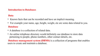
Introduction to Databases
Data
•Known facts that can be recorded and have an implicit meaning.
• For example your name, age, height, weight, etc are some data related to you.
Database
• A database is a collection of related data.
• An online telephone directory would definitely use database to store data
pertaining to people, phone numbers, other contact details, etc.
Database management system (DBMS) is a collection of programs that enables
users to create and maintain a database.
5.
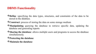
DBMS Functionality
Define :specifyingthe data types, structures, and constraints of the data to be
stored in the database.
Construct: process of storing the data on some storage medium
Manipulating querying the database to retrieve specific data, updating the
database and generating reports
Sharing the database: allows multiple users and programs to access the database
simultaneously.
Protecting the database
Maintain the database
Main Characteristics ofthe Database Approach
1. Self-describing nature of a database system
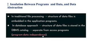
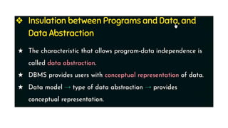
2.Insulation between programs and data, and Data Abstraction
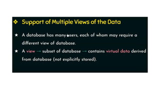
3. Support of multiple views of the data
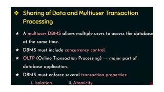
4. Sharing of data and multi-user transaction processing:
9.
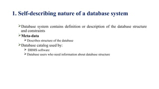
1. Self-describing natureof a database system
Database system contains definition or description of the database structure
and constraints
Meta-data
Describes structure of the database
Database catalog used by:
DBMS software
Database users who need information about database structure
Database users
Actors onthe Scene Workers behind the scene
Actors on the Scene
• Those who actually use and control the database content,
and those who design, develop and maintain database
applications.
Workers behind the scene
• Those who design and develop the DBMS software and
related tools, and the computer systems operators
18.
1.Actors on theScene
- Identify the people whose jobs involve the day-to-day
use of a large database
Database Administrators
Database Designers
End Users
Casual end users
Naive or parametric end users
Sophisticated end users
Standalone users
System Analysts and Application Programmers
(Software Engineers)
19.
Database administrator (DBA).
DBAis responsible for
• Administering the resources.
• responsible for authorizing access to the database, coordinating and monitoring its use, and
acquiring software and hardware resources as needed.
• The DBA is accountable for problems such as security breaches and poor system response
time.
• Installing and Configuration of database
• Decides Data Recovery and Back up method
• Decides validation checks on data
• A DBA monitors the CPU and memory usage.
• Provides help and support to user
20.
Database Designers
• Databasedesigners are responsible for identifying the data to be stored in the
database and for choosing appropriate structures to represent and store this data.
• It is the responsibility of database designers to communicate with all prospective
database users in order to understand their requirements and to create a design that
meets these requirements.
21.
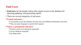
End Users
• Endusers are the people whose jobs require access to the database for
querying,updating, and generating reports
• There are several categories of end users:
Casual end users :
occasionally access the database, but they may need different information each time.
They use query language to specify their requests.
Naive or parametric end users
Perform small set of operations repeatedly
Access database frequently
Eg: Bank tellers
22.
• Sophisticated endusers include engineers, scientists, business
analysts implement their own applications to meet their
complex requirements.
• Standalone users maintain personal databases by using ready-
made program packages that provide easy-to-use menu-based
or graphics-based interfaces.
23.
System Analysts andApplication Programmers
(Software Engineers)
• System analysts determine the requirements of end users, and develop
specifications for standard canned transactions that meet these requirements.
• Application programmers implement these specifications as programs; then they
test, debug, document, and maintain these canned transactions. Such analysts and
programmers—commonly referred to as software developers or software
engineers—
24.
Workers behind theScene
• People are involved in design, development, and operation of the DBMS software
and system environment.
• DBMS system designers and implementers design and implement the DBMS
modules and interfaces as a software package.
• Tool developers design and implement tools—the software packages that
facilitate database modeling and design, database system design, and improved
performance
• Operators and maintenance personnel (system administration personnel)are
responsible for the actual running and maintenance of the hardware and software
environment for the database system.
25.
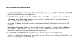
Disadvantage of File-orientedsystem:
• 1. Data Redundancy: It is possible that the same information may be duplicated in different files. This leads
to data redundancy results in memory wastage.
• 2. Data Inconsistency: Because of data redundancy, it is possible that data may not be in consistent state.
• 3. Difficulty in Accessing Data: Because of data redundancy and inconsistency, it would be tedious to
access the data spread across different files.
• 4. Integrity Problems: Data integrity means that the data contained in the database in both correct and
consistent.
• 5. Limited Data Sharing: Becuase of data redundancy, data’s are scattered in various files. And different
files may have different formats and these files may be stored in different folders. So, due to this data
isolation, it is difficult to share data among different applications.
• 6. Concurrent Access Anomalies: Multiple users are allowed to access data simultaneously
• 7. Security Problems: Database should be accessible to users in limited way. Each user should be allowed to
access data concerning his requirements only
26.
Advantages of DBMS
Controlling Redundancy
Restricting unauthorized access
Providing Persistent storage for program objects
Providing Backup and Recovery
Providing Multiple user Interfaces
Representing Complex Relationships among data
Enforcing Integrity Constraints
Permitting Inferencing and Actions using rules
Additional implications of using the database
approach
27.
Controlling Redundancy
• Storingthe same data multiple times is called redundancy
• Redundancy leads to several problems
Duplication of effort
Storage space is wasted
Inconsistency
In database all the data item is stored in one place in the database.
28.
Restricting Unauthorized Access
•When multiple users share a large database, most users will not be authorized to
perform all operations on the database
• Eg: financial data
• DBMS provide authorization subsytem in which DBA uses to create accounts
and to specify account restrictions.
31.
Providing Persistent Storagefor Program Objects
• Databases can be used to provide persistent storage for program objects and data
structures.
• Object-oriented database systems typically offer data structure compatibility with
one or more object-oriented programming languages.
32.
Providing Storage Structuresand Search
Techniques for Efficient Query Processing
• Database systems must provide capabilities for efficiently executing queries and
updates.
• DBMS must provide specialized data structures and search techniques to speed up
disk search for the desired records. Auxiliary files called indexes are used for this
purpose.
• The query processing and optimization module of the DBMS is responsible for
choosing an efficient query execution plan for each query based on the existing
storage structures.
33.
Providing Backup andRecovery
• A DBMS must provide facilities for recovering from hardware or software
failures.
• The backup and recovery subsystem of the DBMS is responsible for recovery.
34.
Providing Multiple UserInterfaces
• DBMS should provide a variety of user interfaces because many types of users
with varying levels of technical knowledge use a database.
35.
Representing Complex Relationshipsamong Data
• A database contains many varieties of data that are interrelated in many ways.
• A DBMS has capability to represent a variety of complex relationships among the
data as well as to retrieve and update related data easily and efficiently
36.
Enforcing Integrity Constraints
•Most database applications have certain integrity constraints that must hold for
the data.
• Eg:a Grade field could be defined to be of type Grade_Type {A,B,C}
• A DBMS should provide capabilities for defining and enforcing these constraints.
• The simplest type of integrity constraint involves specifying a data type for each
data item.
Key or uniqueness constraint
•Every student record must have a unique value for roll number.
37.
Permitting Inferencing andActions Using Rules
• Some database systems allows rules for inferencing(retrieving) information from
the stored database. Such rules are called as deduction rules and the systems are
called as deductive database systems
38.
Additional Implications ofUsing
the Database Approach
• Potential for Enforcing Standards.
DBA define and enforce standards in a centralized database environment.
Standards can be defined for names and formats of data elements, display formats,
report structures etc.
• Reduced Application Development Time.
once a database is created and ready to use, less time is required to create new
applications using DBMS facilities.
Retrieval of certain data from the database takes very less time.
39.
• Flexibility
Necessary tochange the structure of a database as requirements
change
Availability of Up-to-Date Information.
A DBMS makes the database available to all users.
If one user update the database, all other users can immediately
see this update
40.
When Not toUse a DBMS
• DBMS involve unnecessary overhead costs that is not incurred
in traditional file processing. The overhead costs of using a
DBMS are due to the following:
High initial investment in hardware, software, and training
Overhead for providing security, concurrency control, recovery, and
integrity functions
• Therefore, it may be more desirable to file processing approach
under the following circumstances:
• Simple, well-defined database applications that are not
expected to change at all
• No multiple-user access to data
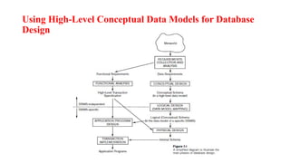
• The databasedesign using high-level conceptual data models
consists of different phases
Requirements collection and analysis
The database designers interview database users to understand
and document their data requirements. These requirements
should be specified in as detailed and complete.
In parallel with specifying the data requirements, it is useful to
specify the known functional requirements of the application.
Functional requirements consists of the user defined operations
that will be applied to the database, including both retrieval and
updates
45.
Conceptual design
Once allthe requirements have been collected and analyzed,
the next step is to create a conceptual schema for the database
using high level conceptual data model. This step is called
conceptual design.
Conceptual schema includes detailed description of the entity
types, relationships and constraints
Logical design
After the conceptual design, the next step in database design is
the actual implementation of the database, using a commercial
DBMS.
The conceptual schema is transformed from the high-level data
model into the implementation data model using DBMS.
This step is called logical design or data model mapping; its
result is a database schema in the implementation data model of
the DBMS.
46.
Physical Design
The laststep is the physical design phase, during which the
internal storage structures, file organizations, indexes, access
paths, and physical design parameters for the database files are
specified.
In parallel with these activities, application programs are
designed and implemented as database transactions
47.
Data model—a collectionof concepts that can be used to
describe the structure of a database
Categories of Data Models
Data models have been categorized according to the types of
concepts used to describe the database structure
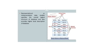
High-level or conceptual data models
low-level or physical data models
representational (or implementation) data models,
High-level or conceptual data models :
It provide concepts that are close to the way many users
perceive data.
Conceptual data models use concepts such as entities,
attributes, and relationships.
48.
An entity representsa real-world object or concept, such as an employee or
a project
An attribute describes an entity, such as the employee’s name or salary.
Relationships are used to define relations among different entitiesfor
example, a works-on relationship between an employee and a project
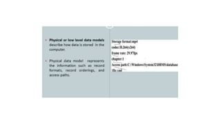
Low-level or physical data models
It provide concepts that describe the details of how data is stored in the
computer.
• By representing information such as record formats, record orderings, and
access paths.
• An access path is a structure that makes the search for particular database
records efficient
50.
Representational (or implementation)data models,
It provide concepts that may be easily understood by end users
,but it hides many details of data storage.
It is used most frequently in traditional commercial DBMSs.
These include relational data model,network and
hierarchical models.
Representational data models represent data by using record
structures and hence are called record-based data models.
52.
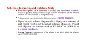
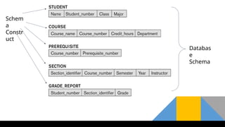
Schemas, Instances, andDatabase State
• The description of a database is called the database schema.
Which is specified during database design Includes descriptions of the database
structure and is not expected to change frequently.
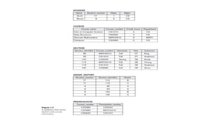
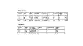
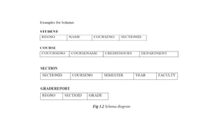
• A diagrammatic representation of a database schema.-schema diagram.
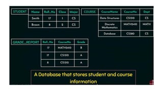
• Figure shows a schema diagram which displays the structure of
each record type but not the actual instances of records. We call
each object in the schema—such as STUDENT or COURSE as
a schema construct.
• Schema Construct: A component of the schema or an object within the schema,
e.g., STUDENT, COURSE
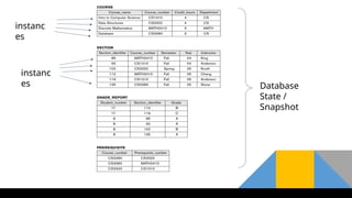
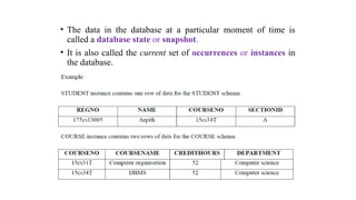
• The datain the database at a particular moment of time is
called a database state or snapshot.
• It is also called the current set of occurrences or instances in
the database.
57.
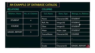
• The DBMSstores the descriptions of the schema constructs and
constraints—also called the meta-data
• The schema is sometimes called the intension, and a database
state is called an extension of the schema.
58.
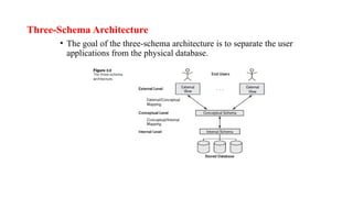
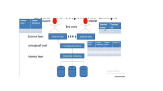
Three-Schema Architecture
• Thegoal of the three-schema architecture is to separate the user
applications from the physical database.
59.
Schemas can bedefined at the following three levels:
The internal level :
Has an internal schema
Describes the physical storage structure of the database.
The internal schema uses a physical data model and describes
the complete details of data storage and access paths for the
database.
The conceptual level
Has a conceptual schema,
which describes the structure of the whole database for a
community of users.
The conceptual schema hides the details of physical storage
structures and concentrates on describing entities, data types,
relationships, user operations, and constraints.
.
60.
The external orview level
includes a number of external schemas or user views.
Each external schema describes the part of the database that a
particular user group is interested in and hides the rest of the
database from that user group.
An external schema is described in a high-level data model.
The processes of transforming requests and results between
levels are called mappings.
62.
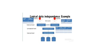
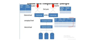
Data Independence
Data independencecan be defined as the capacity to change the
schema at one level of a database system without having to change the
schema at the next higher level.
Two types of data independence:
Logical data independence is the capacity to change the conceptual
schema(structure of the file)without having to change external schemas
or application programs.
We can change the structure of the file by adding extra fields or by
removing the fields.
Physical data independence is the capacity to change the internal
schema(physical storage) without having to change the conceptual
schema( structure of the file)
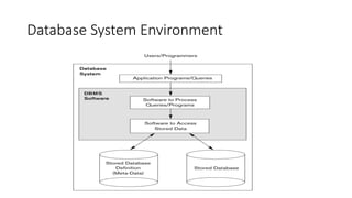
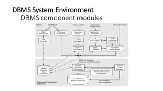
The figure isdivided into two parts.
The top part of the figure refers to the various users of the database
environment and their interfaces.
The lower part shows the internals of the DBMS responsible for
storage of data and processing of transactions.
DBMS Components modules are:
Stored data manager
DDL compiler
Interactive query interface
Query compiler
Query optimizer
Precompiler
Runtime database processor
System catalog
Concurrency control system
Backup and recovery system
67.
• The databaseand the DBMS catalog are usually stored on disk. Access to the disk is controlled
primarily by the operating system (OS), which schedules disk read/write.
• DBMSs have their own buffer management module to schedule disk read/write
• It shows interfaces for the DBA staff, casual users who work with interactive interfaces to
formulate queries, application programmers who create programs using some host
programming languages, and parametric users who do data entry work by supplying
parameters to predefined transactions.
• The DBA staff works on defining the database and tuning it by making changes to its
definition using the DDL and other privileged commands.
• The DDL compiler processes schema definitions, specified in the DDL, and stores descriptions
of the schemas (meta-data) in the DBMS catalog. The catalog includes information such as the
names and sizes of files, names and data types of data items, storage details of each file,
mapping information among schemas, and constraints
68.
• Casual usersand persons with occasional need for information from the database interact
using some form of interface,-interactive query interface
69.
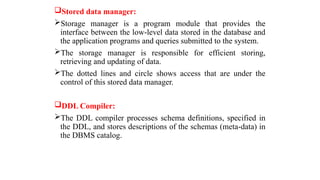
Stored data manager:
Storagemanager is a program module that provides the
interface between the low-level data stored in the database and
the application programs and queries submitted to the system.
The storage manager is responsible for efficient storing,
retrieving and updating of data.
The dotted lines and circle shows access that are under the
control of this stored data manager.
DDL Compiler:
The DDL compiler processes schema definitions, specified in
the DDL, and stores descriptions of the schemas (meta-data) in
the DBMS catalog.
70.
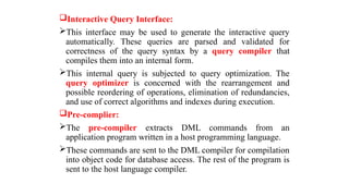
Interactive Query Interface:
Thisinterface may be used to generate the interactive query
automatically. These queries are parsed and validated for
correctness of the query syntax by a query compiler that
compiles them into an internal form.
This internal query is subjected to query optimization. The
query optimizer is concerned with the rearrangement and
possible reordering of operations, elimination of redundancies,
and use of correct algorithms and indexes during execution.
Pre-complier:
The pre-compiler extracts DML commands from an
application program written in a host programming language.
These commands are sent to the DML compiler for compilation
into object code for database access. The rest of the program is
sent to the host language compiler.
71.
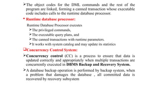
The object codesfor the DML commands and the rest of the
program are linked, forming a canned transaction whose executable
code includes calls to the runtime database processor.
Runtime database processor:
Runtime Database Processor executes
The privileged commands,
The executable query plans, and
The canned transactions with runtime parameters.
It works with system catalog and may update its statistics
Concurrency Control System:
Concurrency control (CC) is a process to ensure that data is
updated correctly and appropriately when multiple transactions are
concurrently executed in DBMS Backup and Recovery System.
A database backup operation is performed by backup system, when
a problem that damages the database , all committed data is
recovered by recovery subsystem
72.
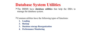
Database System Utilities
TheDBMS have database utilities that help the DBA to
manage the database system.
Common utilities have the following types of functions:
1. Loading
2. Backup
3. Database storage Reorganization
4. Performance Monitoring
73.
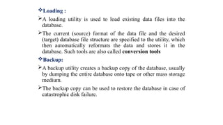
Loading :
A loadingutility is used to load existing data files into the
database.
The current (source) format of the data file and the desired
(target) database file structure are specified to the utility, which
then automatically reformats the data and stores it in the
database. Such tools are also called conversion tools
Backup:
A backup utility creates a backup copy of the database, usually
by dumping the entire database onto tape or other mass storage
medium.
The backup copy can be used to restore the database in case of
catastrophic disk failure.
74.
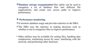
Database storage reorganization:Thisutility can be used to
reorganize a set of database files into different file
organizations, and create new access paths to improve
performance.
Performance monitoring.
It monitors database usage and provides statistics to the DBA.
The DBA uses the statistics in making decisions such as
whether or not to reorganize files to improve performance.
• Other utilities may be available for sorting files, handling data
compression, monitoring access by users, interfacing with the
network, and performing other functions.
75.
Tools, Application Environments,and Communications Facilities
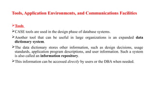
Tools
CASE tools are used in the design phase of database systems.
Another tool that can be useful in large organizations is an expanded data
dictionary system.
The data dictionary stores other information, such as design decisions, usage
standards, application program descriptions, and user information. Such a system
is also called an information repository.
This information can be accessed directly by users or the DBA when needed.
76.
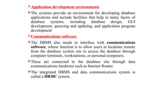
Application development environments
Thesystems provide an environment for developing database
applications and include facilities that help in many facets of
database systems, including database design, GUI
development, querying and updating, and application program
development
Communications software
The DBMS also needs to interface with communications
software, whose function is to allow users at locations remote
from the database system site to access the database through
computer terminals, workstations, or personal computers.
These are connected to the database site through data
communications hardware such as Internet Router.
The integrated DBMS and data communications system is
called a DB/DC system.
77.
Centralized and Client/Server
Architecturesfor DBMSs
Centralized DBMSs Architecture:
Centralized DBMS combines everything into single
system including- DBMS software, hardware, application
programs and user interface processing software.
User can connect through a remote terminal – however, all
processing is done at centralized site.
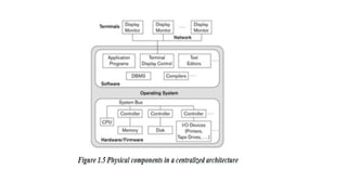
Figure 1.5 illustrates the physical components in a
centralized architecture. Gradually, DBMS systems started
to exploit the available processing power at the user side,
which led to client/server DBMS architectures.
79.
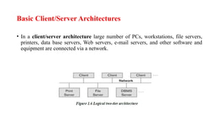
Basic Client/Server Architectures
•In a client/server architecture large number of PCs, workstations, file servers,
printers, data base servers, Web servers, e-mail servers, and other software and
equipment are connected via a network.
80.
• In thisarchitecture, each server will define specific
functionalities.
• It is possible to connect a number of PCs or small workstations
as clients to a file server that maintains the files of the client
machines.
• Another machine can be designated as a printer server by
being connected to various printers; all print requests by the
clients are forwarded to this machine.
• A client in this framework is typically a user machine that
provides user interface capabilities and local processing
• A server is a system containing both hardware and software
that can provide services to the client machines, such as file
access, printing, archiving, or database access
81.
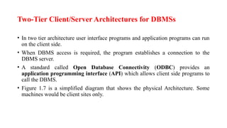
Two-Tier Client/Server Architecturesfor DBMSs
• In two tier architecture user interface programs and application programs can run
on the client side.
• When DBMS access is required, the program establishes a connection to the
DBMS server.
• A standard called Open Database Connectivity (ODBC) provides an
application programming interface (API) which allows client side programs to
call the DBMS.
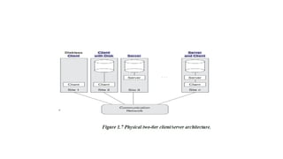
• Figure 1.7 is a simplified diagram that shows the physical Architecture. Some
machines would be client sites only.
83.
A client programcan actually connect to several RDBMSs and
send query and transaction requests using the ODBC API,
which are then processed at the server sites.
Any query results are sent back to the client program, which
can process and display the results as needed.
The architectures described here are called two-tier
architectures because the software Components are distributed
over two systems: client and server.
• A client program can actually connect to several RDBMSs and
send query and transaction requests using the ODBC API,
which are then processed at the server sites. Any query results
are sent back to the client program, which can process and
display the results as needed.
• A related standard for the Java programming language, called
JDBC, has also been defined. This allows Java client programs
to access one or more DBMSs through a standard interface.
84.
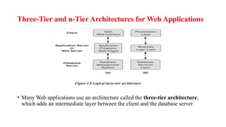
Three-Tier and n-TierArchitectures for Web Applications
• Many Web applications use an architecture called the three-tier architecture,
which adds an intermediate layer between the client and the database server
85.
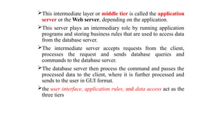
This intermediate layeror middle tier is called the application
server or the Web server, depending on the application.
This server plays an intermediary role by running application
programs and storing business rules that are used to access data
from the database server.
The intermediate server accepts requests from the client,
processes the request and sends database queries and
commands to the database server.
The database server then process the command and passes the
processed data to the client, where it is further processed and
sends to the user in GUI format.
the user interface, application rules, and data access act as the
three tiers
86.
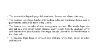
• The presentationlayer displays information to the user and allows data entry
• The business logic layer handles intermediate rules and constraints before data is
passed up to the user or down to the DBMS
• The bottom layer includes all data management services. The middle layer can
also act as a Web server, which retrieves query results from the database server
and formats them into dynamic Web pages that are viewed by the Web browser at
the client side
• If business logic layer is divided into multiple layer, then called as n-tier
architecture
87.
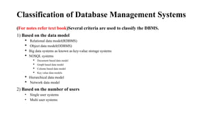
Classification of DatabaseManagement Systems
(For notes refer text book)Several criteria are used to classify the DBMS.
1) Based on the data model
Relational data model(RDBMS)
Object data model(ODBMS)
Big data systems as known as key-value storage systems
NOSQL systems
Document based data model
Graph based data model
Column based data model
Key value data models
Hierarchical data model
Network data model
2) Based on the number of users
• Single user systems
• Multi user systems
88.
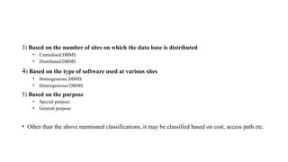
3) Based onthe number of sites on which the data base is distributed
• Centralised DBMS
• Distributed DBMS
4) Based on the type of software used at various sites
• Homogeneous DBMS
• Heterogeneous DBMS
5) Based on the purpose
• Special purpose
• General purpose
• Other than the above mentioned classifications, it may be classified based on cost, access path etc.
89.
DBMS Languages
DBMS Languagesincludes
Data definition language (DDL):
Is used by the DBA and by database designers to define both
schemas.
The DBMS will have a DDL compiler whose function is to process
DDL statements in order to identify descriptions of the schema
constructs and to store the schema description in the DBMS
catalog.
The DDL is used to specify the conceptual schema only.
Storage Definition Language (SDL):
Is used to specify the internal schema.
This permit the DBA staff to control indexing choices and mapping
of data to storage
90.
View Definition Language(VDL), to specify user views and
their mappings to the conceptual schema.
• but in most DBMSs the DDL is used to define both conceptual and external
schemas. In relational DBMSs, SQL is used in the role of VDL to define user
or application views as results of predefined queries
Data Manipulation Language (DML):
Is used to manipulate the data within the database.
It includes manipulations like retrieval, insertion, deletion, and
modification of the data. The DBMS provides a set of
operations or a language called the Data manipulation
language (DML)
• There are two main types of DMLs.
High-level or nonprocedural DML
Lowlevel or procedural DML
91.
A Low-levelor Procedural DML:
retrieves individual records or objects from the database and processes each
separately.
Low-level DMLs are also called record-at-a-time DMLs.
High-level or Nonprocedural DML :
• Many DBMSs allow high-level DML statements either to be entered
interactively from a display monitor or terminal or to be embedded in a
general-purpose programming language.
DML statements must be identified within the program so that they can be
extracted by a precompiler and processed by the DBMS.
Highlevel DMLs, such as SQL, can specify and retrieve many records in a
single DML statement; therefore, they are called set-at-a-time or set-
oriented DMLs
A query in a high-level DML often specifies which data to retrieve rather
than how to retrieve it; therefore, such languages are also called
declarative.
92.
• Whenever DMLcommands, whether high level or low level,
are embedded in a general-purpose programming language, that
language is called the host language and the DML is called the
data sublanguage.
• A high-level DML used in a standalone interactive manner is
called a query language.
93.
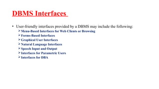
DBMS Interfaces
• User-friendlyinterfaces provided by a DBMS may include the following:
Menu-Based Interfaces for Web Clients or Browsing
Forms-Based Interfaces
Graphical User Interfaces
Natural Language Interfaces
Speech Input and Output
Interfaces for Parametric Users
Interfaces for DBA
94.
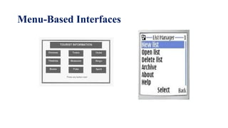
Menu-Based Interfaces forWeb Clients or Browsing :
This interfaces present the user with lists of options called
menus.
the user need not remember the commands memorize and
syntax of a query
the query is constructed step-by step by picking options from a
menu that is displayed by the system.
Pull-down menus are a very popular technique in Web-based
user interfaces
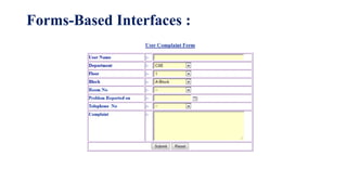
Forms-Based Interfaces :
displaysa form to each user.
Users can fill out all of the form entries to insert new data, or
they can fill out only certain entries, in which case the DBMS
will retrieve matching data for the remaining entries.
Forms are usually designed and programmed for naive users as
interfaces to canned transactions.
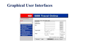
Graphical User Interfaces
AGUI typically displays a schema to the user in diagrammatic
form. The user then can specify a query by manipulating the
diagram. GUIs utilize both menus and forms.
GUIs use a pointing device, such as a mouse, to select certain
parts of the displayed schema diagram.
Natural Language Interfaces
Acceptsthe requests written in English and tries to understand
them.
If it is understood, the interface generates high level query and
sends it to the DBMS for processing.
102.
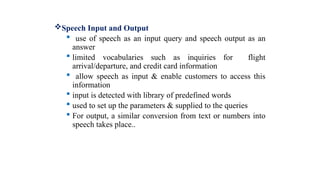
Speech Input andOutput
use of speech as an input query and speech output as an
answer
limited vocabularies such as inquiries for flight
arrival/departure, and credit card information
allow speech as input & enable customers to access this
information
input is detected with library of predefined words
used to set up the parameters & supplied to the queries
For output, a similar conversion from text or numbers into
speech takes place..
103.
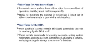
Interfaces for ParametricUsers :
Parametric users, such as bank tellers, often have a small set of
operations that they must perform repeatedly.
Hence to minimize the number of keystrokes a small set of
abbreviated commands is provided in this interface.
Interfaces for the DBA
Most database systems contain privileged commands that can
be used only by the DBA staff.
These include commands for creating accounts, setting system
parameters, granting account authorization, changing a schema,
and reorganizing the storage structures of a database.
104.
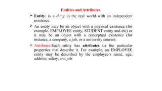
Entities and Attributes
Entity: is a thing in the real world with an independent
existence.
An entity may be an object with a physical existence (for
example, EMPLOYEE entity, STUDENT entity and etc) or
it may be an object with a conceptual existence (for
instance, a company, a job, or a university course).
Attributes:Each entity has attributes i.e the particular
properties that describe it. For example, an EMPLOYEE
entity may be described by the employee’s name, age,
address, salary, and job
105.
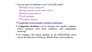
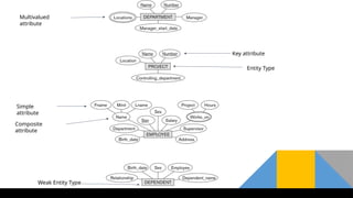
• Several typesof attributes occur in the ER model:
Simple versus composite
Single valued versus multi-valued
Stored versus derived
Null Attribute
Complex attribute
Composite versus Simple (Atomic) Attributes.
Composite attributes can be divided into smaller subparts,
which represent more basic attributes with independent
meanings.
For example, The Name attribute of the EMPLOYEE entity
can be divided into FirstName, Middle Name and LastName.
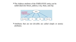
106.
The Address attributeof the EMPLOYEE entity can be
subdivided into Street_address, City, State, and Zip.
Attributes that are not divisible are called simple or atomic
attributes.
107.
Single-Valued versus MultivaluedAttributes :
Single –valued attribute is an attribute that can have
only a single value
For example, a person can have only one roll number
and age
An attribute that can have more than one value is
called multivalued attribute.
For example the degree attribute of a person can have
multiple values if the person has completed multiple
degrees like B.E,M.tech,Ph.D
A customer can have more than one mobile number.
108.
Stored versus DerivedAttributes.
If an attribute can be calculated using the value of another
attribute, they are called as derived attribute. Or These
attributes are derived from another attributes
The attribute that is used to derive the attribute is called a
stored attribute or Attributes cannot be derived from other
attribute.
For example,the value of Age can be determined from the
current (today’s) date and the value of that person’s Birth_date.
The Age attribute is hence called a derived attribute and is
said to be derivable from the Birth_date attribute, which is
called a stored attribute
109.
NULL Values.
The Attributemay not have an applicable value for it.
For example, Email attribute, some people may have email id.
For those who do not have email id, then the value will be
NULL for an Email attribute.
The unknown category of NULL can be further classified into
two cases.
The first case arises when it is known that the attribute
value exists but is missing for example, if the Height
attribute of a person is listed as NULL.
The second case arises when it is not known whether the
attribute value exists or not. for example, if the Email
attribute of a person is NULL.
110.
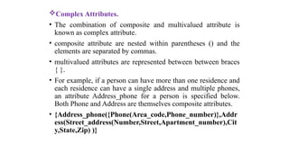
Complex Attributes.
• Thecombination of composite and multivalued attribute is
known as complex attribute.
• composite attribute are nested within parentheses () and the
elements are separated by commas.
• multivalued attributes are represented between between braces
{ }.
• For example, if a person can have more than one residence and
each residence can have a single address and multiple phones,
an attribute Address_phone for a person is specified below.
Both Phone and Address are themselves composite attributes.
• {Address_phone({Phone(Area_code,Phone_number)},Addr
ess(Street_address(Number,Street,Apartment_number),Cit
y,State,Zip) )}
112.
ER Model Concepts...
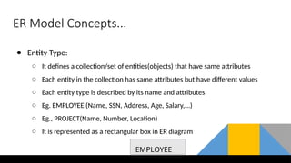
●Entity Type:
○ It defines a collection/set of entities(objects) that have same attributes
○ Each entity in the collection has same attributes but have different values
○ Each entity type is described by its name and attributes
○ Eg. EMPLOYEE (Name, SSN, Address, Age, Salary,...)
○ Eg., PROJECT(Name, Number, Location)
○ It is represented as a rectangular box in ER diagram
EMPLOYEE
113.
ER Model Concepts...
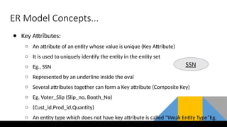
●Key Attributes:
○ An attribute of an entity whose value is unique (Key Attribute)
○ It is used to uniquely identify the entity in the entity set
○ Eg., SSN
○ Represented by an underline inside the oval
○ Several attributes together can form a Key attribute (Composite Key)
○ Eg. Voter_Slip (Slip_no, Booth_No)
○ (Cust_id,Prod_id,Quantity)
○ An entity type which does not have key attribute is called “Weak Entity Type”Eg.
SSN
114.
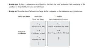
• Entity type:defines a collection (or set) of entities that have the same attributes. Each entity type in the
database is described by its name and attributes
• Entity set;The collection of all entities of a particular entity type in the database at any point in time
115.
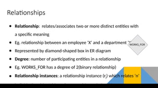
Relationships
● Relationship: relates/associatestwo or more distinct entities with
a specific meaning
● Eg. relationship between an employee ‘X’ and a department ‘Y’
● Represented by diamond-shaped box in ER diagram
● Degree: number of participating entities in a relationship
● Eg. WORKS_FOR has a degree of 2(binary relationship)
● Relationship instances: a relationship instance (rj) which relates ‘n’
individual entities/objects (e1,e2,...en) in a relationship
WORKS_FOR
116.
● Role namesignifies the role that a participating entity from the entity type plays in each relationship instance, and
helps to explain what the relationship means.
● For example, in the WORKS_FOR relationship type, EMPLOYEE plays the role of employee or worker and
DEPARTMENT plays the role of department or employer
117.
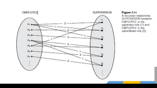
Relationships...
● Recursive RelationshipType:
○ A relationship type which relates same entity type but with different roles
○ Eg. SUPERVISION relationship
○ SUPERVISION relates 2 EMPLOYEE entities with different roles as:
Supervisor(boss) and Supervisee (subordinate)
119.
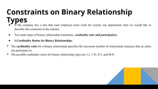
Constraints on BinaryRelationship
Types
● If the company has a rule that each employee must work for exactly one department, then we would like to
describe this constraint in the schema.
● Two main types of binary relationship constraints: cardinality ratio and participation.
● 1.Cardinality Ratios for Binary Relationships.
The cardinality ratio for a binary relationship specifies the maximum number of relationship instances that an entity
can participate in.
The possible cardinality ratios for binary relationship types are 1:1, 1:N, N:1, and M:N.
120.
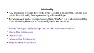
Relationship
• Any associationbetween two entity types is called a relationship. Entities take
part in the relationship. It is represented by a diamond shape.
• For example, A teacher teaches students. Here, "teaches" is a relationship and this
is the relationship between a Teacher entity and a Student entity.
There are four types of relationships that can exist between two entities.
• One-to-One Relationship
• One-to-Many
• Many-to-One Relationship
• Many-to-Many Relationship
121.
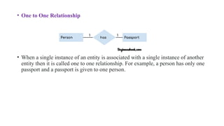
• One toOne Relationship
• When a single instance of an entity is associated with a single instance of another
entity then it is called one to one relationship. For example, a person has only one
passport and a passport is given to one person.
122.
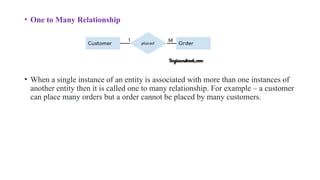
• One toMany Relationship
• When a single instance of an entity is associated with more than one instances of
another entity then it is called one to many relationship. For example – a customer
can place many orders but a order cannot be placed by many customers.
123.
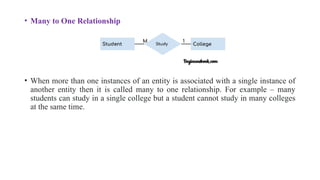
• Many toOne Relationship
• When more than one instances of an entity is associated with a single instance of
another entity then it is called many to one relationship. For example – many
students can study in a single college but a student cannot study in many colleges
at the same time.
124.
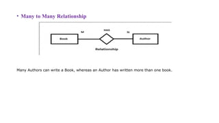
• Many toMany Relationship
Many Authors can write a Book, whereas an Author has written more than one book.
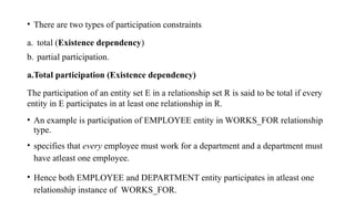
• There aretwo types of participation constraints
a. total (Existence dependency)
b. partial participation.
a.Total participation (Existence dependency)
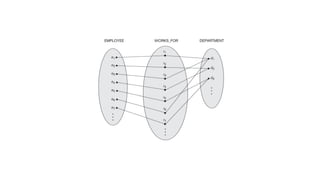
The participation of an entity set E in a relationship set R is said to be total if every
entity in E participates in at least one relationship in R.
• An example is participation of EMPLOYEE entity in WORKS_FOR relationship
type.
• specifies that every employee must work for a department and a department must
have atleast one employee.
• Hence both EMPLOYEE and DEPARTMENT entity participates in atleast one
relationship instance of WORKS_FOR.
128.
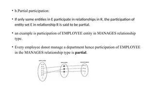
• b.Partial participation:
•If only some entities in E participate in relationships in R, the participation of
entity set E in relationship R is said to be partial.
• an example is participation of EMPLOYEE entity in MANAGES relationship
type.
• Every employee donot manage a department hence participation of EMPLOYEE
in the MANAGES relationship type is partial.
129.
• Types ofEntity type
• Strong Entity Type
• Weak Entity Type
130.
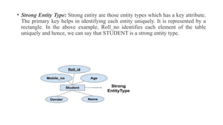
• Strong EntityType: Strong entity are those entity types which has a key attribute.
The primary key helps in identifying each entity uniquely. It is represented by a
rectangle. In the above example, Roll_no identifies each element of the table
uniquely and hence, we can say that STUDENT is a strong entity type.
131.
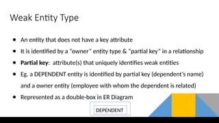
Weak Entity Type
●An entity that does not have a key attribute
● It is identified by a “owner” entity type & “partial key” in a relationship
● Partial key: attribute(s) that uniquely identifies weak entities
● Eg. a DEPENDENT entity is identified by partial key (dependent’s name)
and a owner entity (employee with whom the dependent is related)
● Represented as a double-box in ER Diagram
DEPENDENT
132.
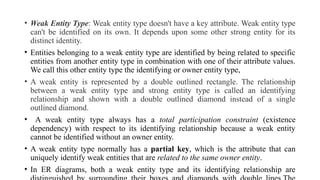
• Weak EntityType: Weak entity type doesn't have a key attribute. Weak entity type
can't be identified on its own. It depends upon some other strong entity for its
distinct identity.
• Entities belonging to a weak entity type are identified by being related to specific
entities from another entity type in combination with one of their attribute values.
We call this other entity type the identifying or owner entity type,
• A weak entity is represented by a double outlined rectangle. The relationship
between a weak entity type and strong entity type is called an identifying
relationship and shown with a double outlined diamond instead of a single
outlined diamond.
• A weak entity type always has a total participation constraint (existence
dependency) with respect to its identifying relationship because a weak entity
cannot be identified without an owner entity.
• A weak entity type normally has a partial key, which is the attribute that can
uniquely identify weak entities that are related to the same owner entity.
• In ER diagrams, both a weak entity type and its identifying relationship are
• There aretwo types of participation constraints
a. total (Existence dependency)
b. partial participation.
a.Total participation (Existence dependency)
The participation of an entity set E in a relationship set R is said to be total if every
entity in E participates in at least one relationship in R.
• An example is participation of EMPLOYEE entity in WORKS_FOR relationship
type.
• specifies that every employee must work for a department and a department must
have atleast one employee.
• Hence both EMPLOYEE and DEPARTMENT entity participates in atleast one
relationship instance of WORKS_FOR.
137.
• b.Partial participation:
•If only some entities in E participate in relationships in R, the participation of
entity set E in relationship R is said to be partial.
• an example is participation of EMPLOYEE entity in MANAGES relationship
type.
• Every employee donot manage a department hence participation of EMPLOYEE
in the MANAGES relationship type is partial.
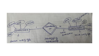
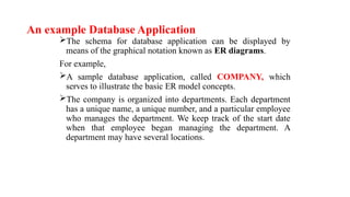
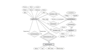
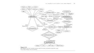
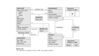
An example DatabaseApplication
The schema for database application can be displayed by
means of the graphical notation known as ER diagrams.
For example,
A sample database application, called COMPANY, which
serves to illustrate the basic ER model concepts.
The company is organized into departments. Each department
has a unique name, a unique number, and a particular employee
who manages the department. We keep track of the start date
when that employee began managing the department. A
department may have several locations.
140.
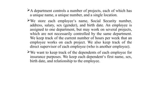
A department controlsa number of projects, each of which has
a unique name, a unique number, and a single location.
We store each employee‘s name, Social Security number,
address, salary, sex (gender), and birth date. An employee is
assigned to one department, but may work on several projects,
which are not necessarily controlled by the same department.
We keep track of the current number of hours per week that an
employee works on each project. We also keep track of the
direct supervisor of each employee (who is another employee).
We want to keep track of the dependents of each employee for
insurance purposes. We keep each dependent‘s first name, sex,
birth date, and relationship to the employee.
141.
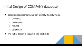
Initial Design ofCOMPANY database
● Based on requirements, we can identify 4 entity types:
○ EMPLOYEE
○ DEPARTMENT
○ PROJECT
○ DEPENDENT
● The initial design is shown in the next slide
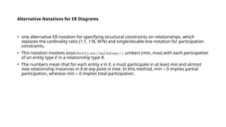
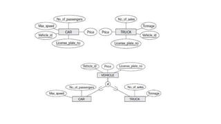
Alternative Notations forER Diagrams
• one alternative ER notation for specifying structural constraints on relationships, which
replaces the cardinality ratio (1:1, 1:N, M:N) and single/double-line notation for participation
constraints.
• This notation involves associating a pair of integer numbers (min, max) with each participation
of an entity type E in a relationship type R,
• The numbers mean that for each entity e in E, e must participate in at least min and atmost
max relationship instances in R at any point in time. In this method, min = 0 implies partial
participation, whereas min > 0 implies total participation.
146.
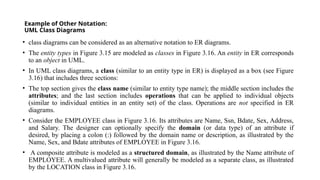
Example of OtherNotation:
UML Class Diagrams
• class diagrams can be considered as an alternative notation to ER diagrams.
• The entity types in Figure 3.15 are modeled as classes in Figure 3.16. An entity in ER corresponds
to an object in UML.
• In UML class diagrams, a class (similar to an entity type in ER) is displayed as a box (see Figure
3.16) that includes three sections:
• The top section gives the class name (similar to entity type name); the middle section includes the
attributes; and the last section includes operations that can be applied to individual objects
(similar to individual entities in an entity set) of the class. Operations are not specified in ER
diagrams.
• Consider the EMPLOYEE class in Figure 3.16. Its attributes are Name, Ssn, Bdate, Sex, Address,
and Salary. The designer can optionally specify the domain (or data type) of an attribute if
desired, by placing a colon (:) followed by the domain name or description, as illustrated by the
Name, Sex, and Bdate attributes of EMPLOYEE in Figure 3.16.
• A composite attribute is modeled as a structured domain, as illustrated by the Name attribute of
EMPLOYEE. A multivalued attribute will generally be modeled as a separate class, as illustrated
by the LOCATION class in Figure 3.16.
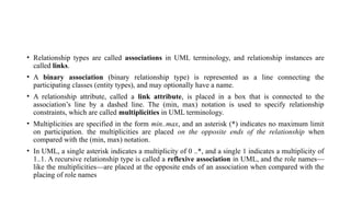
147.
• Relationship typesare called associations in UML terminology, and relationship instances are
called links.
• A binary association (binary relationship type) is represented as a line connecting the
participating classes (entity types), and may optionally have a name.
• A relationship attribute, called a link attribute, is placed in a box that is connected to the
association’s line by a dashed line. The (min, max) notation is used to specify relationship
constraints, which are called multiplicities in UML terminology.
• Multiplicities are specified in the form min..max, and an asterisk (*) indicates no maximum limit
on participation. the multiplicities are placed on the opposite ends of the relationship when
compared with the (min, max) notation.
• In UML, a single asterisk indicates a multiplicity of 0 ..*, and a single 1 indicates a multiplicity of
1..1. A recursive relationship type is called a reflexive association in UML, and the role names—
like the multiplicities—are placed at the opposite ends of an association when compared with the
placing of role names
148.
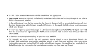
• In UML,there are two types of relationships: association and aggregation.
• Aggregation is meant to represent a relationship between a whole object and its component parts, and it has a
distinct diagrammatic notation.
• In the unidirectional case, the line connecting the classes is displayed with an arrow to indicate that only one
direction for accessing related objects is needed. If no arrow is displayed, the bidirectional case is assumed,
which is the default.
• if we always expect to access the manager of a department starting from a DEPARTMENT object, we would
draw the association line representing the MANAGES association with an arrow from DEPARTMENT to
EMPLOYEE.
• In addition, relationship instances may be specified to be ordered.
• For example, we could specify that the employee objects related to each department through the
WORKS_FOR association (relationship) should be ordered by their Start_date attribute value. Association
(relationship) names are optional in UML, and relationship attributes are displayed in a box attached with a
dashed line to the line representing the association/aggregation (see Start_date and Hours).
149.
• Weak entitiescan be modeled using the UML construct called qualified association (or
qualified aggregation); this can represent both the identifying relationship and the partial
key, which is placed in a box attached to the owner class.
151.
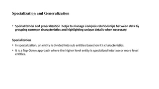
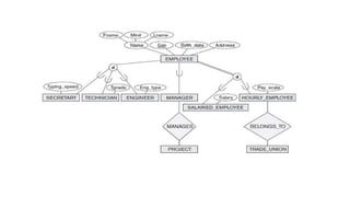
Specialization and Generalization
•Specialization and generalization helps to manage complex relationships between data by
grouping common characteristics and highlighting unique details when necessary.
Specialization
• In specialization, an entity is divided into sub entities based on it’s characteristics.
• It is a Top-Down approach where the higher level entity is specialized into two or more level
entities.
153.
Generalization
• Generalization processof Extracting common properties from a set of entities
and creating a generalized entity from it.
• It is a Bottom-Up approach, in which two or more entities can be generalized to a
higher level entity if they have same attributes in common.
• Generalization is the reverse process of Specialization
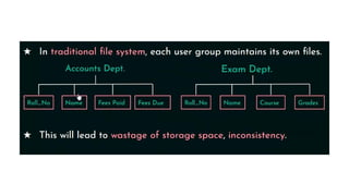
Editor's Notes
#21
Temporary Users/Casual Users − These users utilize the database for testing and are only accessible for a limited time. According to business requirements, these users update a little or new information to the database with the help of a database administrator. It helps to maintain the security and integrity of data.
Parametric End Users are the unsophisticated who don’t have any DBMS knowledge but they frequently use the database applications in their daily life to get the desired results. For example, Railway’s ticket booking users are naive users. Clerks in any bank is a naive user because they don’t have any DBMS knowledge but they still use the database and perform their given task.
#22 Sophisticated users can be engineers, scientists, business analyst, who are familiar with the database. They can develop their own database applications according to their requirement. They don’t write the program code but they interact the database by writing SQL queries directly through the query processor.
#50 This type of data model is used to represent only the logical part of the database and does not represent the physical structure of the database. The representational data model allows us to focus primarily, on the design part of the database