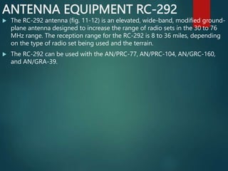
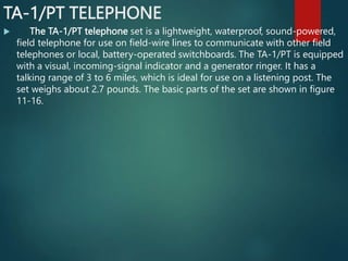
The document provides information about signal communications equipment and procedures used by the military. It discusses various radio sets like the AN/PRC-77 and AN/GRC-160 that are used for voice communication. It also covers telephone equipment and procedures for operating the different radios. The document aims to familiarize readers with the communications systems and how to use them properly.

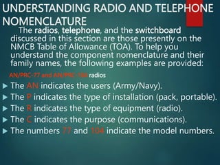
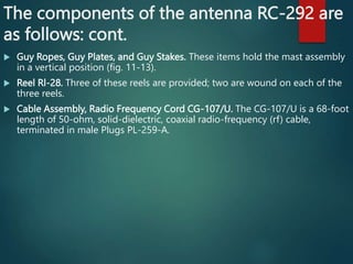
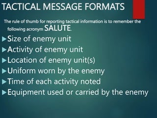
![UNDERSTANDING RADIO AND TELEPHONE
NOMENCLATURE cont.
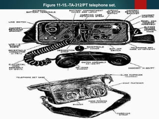
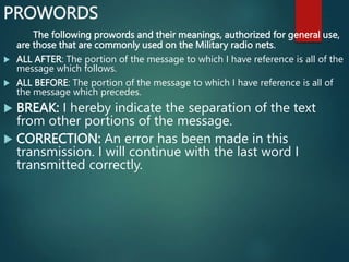
TA-312/PT and TA-1/PT telephones
The TA indicates the type of equipment (telephone apparatus).
The numbers 312 and 1 indicate the model numbers.
The P indicates the installation (pack, portable).
The T indicates the type and purpose of the equipment (telephone [wire]
transmitting).](https://image.slidesharecdn.com/basic-signal-communication-240218120447-e879994f/85/Basic-Signal-Communicationin-the-Army-for-Communication-15-320.jpg)
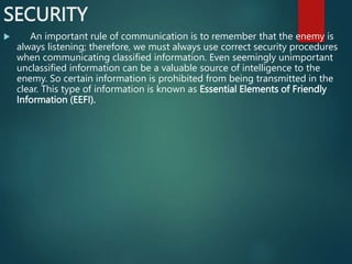
![UNDERSTANDING RADIO AND TELEPHONE
NOMENCLATURE cont.
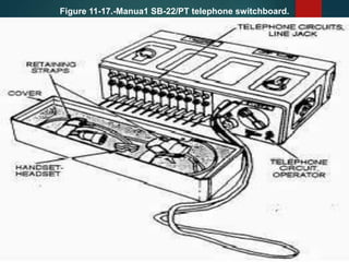
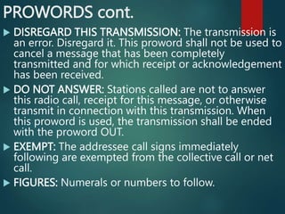
SB-22/PT switchboard
The SB indicates the type of equipment (switchboard).
The number 22 indicates the model number.
The P indicates the installation (pack, portable).
The T indicates the purpose of the equipment (telephone [wire]
transmitting).](https://image.slidesharecdn.com/basic-signal-communication-240218120447-e879994f/85/Basic-Signal-Communicationin-the-Army-for-Communication-16-320.jpg)


![谷歌留痕技术教程[ 𝙩𝙤𝙥 𝟮𝟯𝟯. 𝙘 𝙤𝙢 ]](https://cdn.slidesharecdn.com/ss_thumbnails/top233-260130173900-2eb784f9-thumbnail.jpg?width=640&height=640&fit=bounds)

