Download as PDF, PPTX


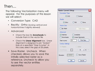
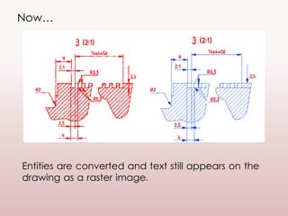
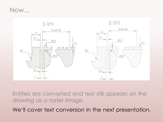


This document provides instructions for basic raster to vector conversion commands in GTXRaster CAD PLUS. It discusses selecting raster data, setting vector conversion options like conversion type and advanced settings, performing vector cleanup after conversion, and saving changes. The goal is to learn how to vectorize geometric entities in a drawing, while keeping text as raster until a future lesson.


