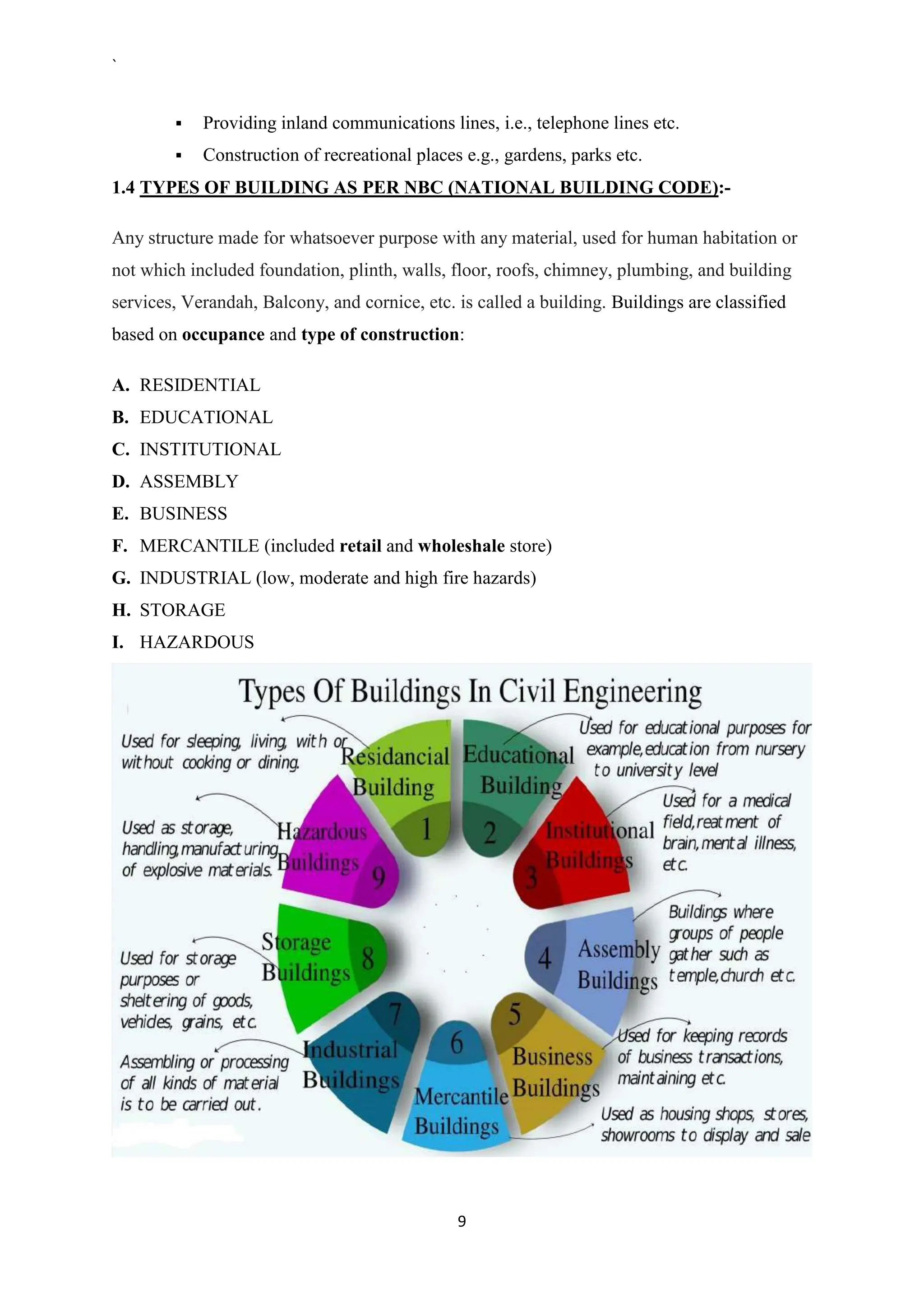
The document provides a detailed syllabus for a basic civil engineering course, covering essential topics such as the introduction to civil engineering, types of buildings, building planning, surveying, and construction technology. It outlines different sub-disciplines of civil engineering, the importance of civil engineering in infrastructure development, building components, and details regarding site selection for buildings. The document also includes references and textbooks for further study.


![ DISADVANTAGES OF IRRIGATION
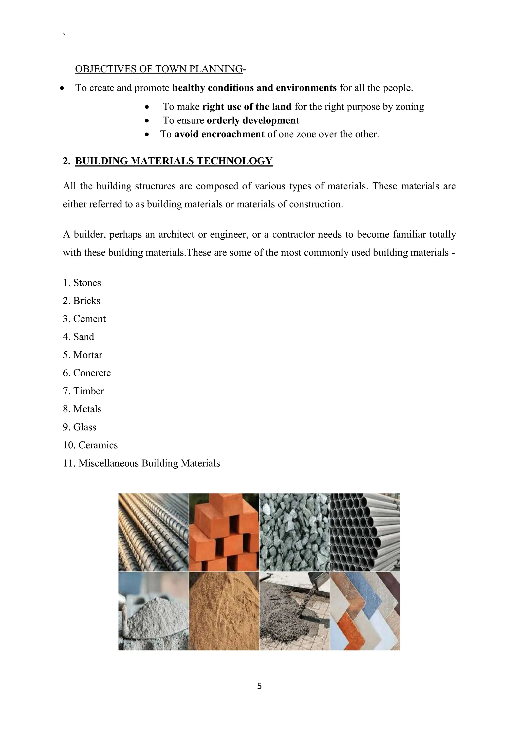
i. Pollution of ground water through seepage of nitrates, causing anaemia.
ii. Colder and damper climate, causing malaria.
iii. Water logging due to over irrigation
iv. Complex and expensive
TYPES OF IRRIGATION
A. Surface irrigation consists of a broad class of irrigation methods in which water is
distributed over the soil surface by gravity flow. The irrigation water is introduced
into level or graded furrows[[Furrow is a long, narrow irrigation trench made in the
ground used for an optimal supply of water. Furrows can be level and are very similar
to long narrow basins. However, a minimum grade of 0.05% is recommended so that
effective drainage can occur following irrigation or excessive rainfall]] or basins,
using siphons, gated pipe, or turnout structures, and is allowed to advance across
the field. Surface irrigation is best suited to flat land slopes, and medium to fine
textured soil types which promote the lateral spread of water down the furrow row or
across the basin.
IRRIGATION
SURFACE
IRRIGATION
FLOW
IRRIGATION
PERRENIAL
IRRIGATION
DIRECT
IRRIGATION
STORAGE
IRRIGATION
FLOOD
IRRIGATION
FLOODING
METHOD
FURROW
METHOD
CONTOUR
METHOD
LIFT
IRRIGATION
SUBSURAFCE
IRRIGATION
NATURAL
METHOD
ARTIFICIAL
METHOD
MODERN
METHODS
SPRINKLER
IRRIGATION
DRIP
IRRIGATION](https://image.slidesharecdn.com/basicofcivil-240703171622-bc62a315/75/Basic-Of-Civil-Engineering-Site-knowledge-218-2048.jpg)


