Baseband Digital Data Transmission
•Download as PPTX, PDF•
2 likes•1,239 views

Satellite Communication

Recommended
More Related Content
What's hot
What's hot (20)
Similar to Baseband Digital Data Transmission
Similar to Baseband Digital Data Transmission (20)
Recently uploaded
Recently uploaded (20)
Baseband Digital Data Transmission
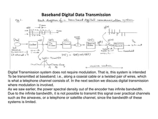
- 1. Baseband Digital Data Transmission Digital Transmission system does not require modulation. That is, this system is intended To be transmitted at baseband; i.e., along a coaxial cable or a twisted pair of wires, which is what a telephone channel consists of. In the next section we discuss digital transmission where modulation is involved. As we saw earlier, the power spectral density out of the encoder has infinite bandwidth. Due to the infinite bandwidth, it is not possible to transmit this signal over practical channels such as the airwaves, or a telephone or satellite channel, since the bandwidth of these systems is limited.
- 2. In order to design a practical communications system, we must limit the bandwidth of the transmitted signal. This may be done by inserting a transmit (Tx) filter, with frequency response denoted by G(f) at the transmitter.
- 3. The block that follows the TX filter in Fig. 1 is the channel, whose frequency response is denoted H(f). The channel is the medium over which the digital signal is transmittede.g. a telephone wire, a fibre optic cable, the airwaves, the coaxial cable etc.
- 4. In the case of a telephone wire for example, the frequency response of the channel rolls off at a rate proportional to 1/f. In most other cases, the frequency response of the channel is flat, except for the case of the airwaves, when multipath is present.
- 5. The effect of thermal and other noise sources is to add a noise process to the receiver input, as shown in Fig. 1. Even though the noise has a very low power level, it can nevertheless significantly impact the performance of the digital transmission system. This is because the signal level is comparable to that of the noise in a typical receiver system.
- 6. Since the noise is a Gaussian process, there is a finite probability that the noise in any bit interval is large enough that it could cause a transmitted bit to appear on the wrong side of the threshold in the decision device. The receiver will then detect the wrong value for that bit, resulting in a bit error. We wish to minimize the probability of occurrence of bit errors.
- 7. The next block in the transmission system of Fig. 1 is the receiver (Rx) filter. This, like the Tx filter, also has a cutoff of approximately 1/2T 3Hz. The purpose of this filter is to reduce the noise power present at the decision device of the receiver, thereby reducing the probability of a bit error and improving performance.
- 8. After the receiver filter, the signal is sampled at the rate of 1/T samples per second. The samples are then fed to a decision device, which is essentially a 1-bit analogue–to–digital convertor. If y(nT) > K, where K is a threshold value, then the corresponding output bit ˆb(nT) = 1; otherwise ˆb(nT) = 0. The threshold value K is typically set to zero.
- 9. THANK YOU