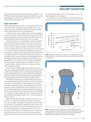
tips & techniques

Why—and How—to Baseline
Your Extruder
When a new extruder is installed, or a new
screw mounted in an existing machine, do
you know what the expected throughput rate
is going to be? You should. If you don’t baseline your extruder, then
how are you going to set realistic expectations for its performance?
If extrusion screws are designed properly, they typically will be
able to withstand the maximum torque available from the extruder
and the resin being processed. The extruder should operate at approximately 90% of its full available torque, based on 100% pellet
feedstock, which typically will be the worst-case scenario. By using
today’s barrier screw technology, higher throughput rates, lower
melt temperatures, and better power efficiencies can be obtained.
This article will provide some basic insight to help processors
to determine if they are obtaining the maximum production rates
from their extruders, providing that they have adequate downstream cooling and handling equipment in the extrusion system.

Fig.1—Using the proper temperature profile when processing
HDPE on a 2-in. extruder can mean substantial differences in
throughput.

Expected Throughput Rates

Twenty years ago, a 3.5-in. (90-mm) extruder with 24:1 L/D
was expected to produce between 500 and 550 lb/hr of HDPE if
it had been fitted with a 125-hp motor and geared for a maximum of 125 rpm. A 2.5-in. (65-mm), 24:1 extruder was expected to obtain 200 to 225 lb/hr of HDPE with a 60-hp motor and
geared for a maximum of 125 rpm.
Nowadays, a 3.5-in. extruder with a 150-hp motor can obtain
650 to 700 lb/hr at 125 rpm and produce a melt temperature
between 410 F and 420 F, against average head pressure of 4000
psi with a fractional-melt HDPE. A 2.5-in. machine should get
you throughput rates in the range of 250 to 275 lb/hr. This can be
achieved using today’s barrier technology vs. the old single-stage
screw with a Maddock (aka LeRoy or Union Carbide) mixer.
But whenever regrind is added to the feedstock, the throughput rate will drop in proportion to the percentage difference in
the overall bulk density of the feedstock. So, if 100% pellets are

By Timothy W. Womer
36 august 2011 Plastics Technology

FIG. 2

Profile for Barrier Screw Processing a Fractional
Melt HDPE
Barrel Zone

Temperature

Zone 1

350° F (177° C)

Zone 2

450° F (232° C)

Zone 3

430° F (221° C)

Zone 4

415° F (213° C)

Zone 5

400° F (204° C)

Fig.2—Typical temperature profile used on a barrier screw
processing fractional-melt HDPE.
extruder baselining
being fed into the extruder with a bulk density of 32 lb/ft3 and
the blend of pellets and regrind weighs only 29 lb/ft 3, the actual
throughput rate could drop by approximately 10%, with all
other conditions being the same.

ture of the flowing polymer, but will more likely measure the
metal temperature of the adapter.
As for IR guns, it is true that they are convenient and sometimes the only way to measure melt temperature while the ex-

What to do first

When purchasing a new extruder or a new screw, ask the vendor
what “theoretical” throughput rate you should expect to get,
and also ask what temperature profile they would recommend
for the material that the screw was designed for.
In the past, when using a single-stage screw with a Maddock
mixer, most extrusion operators would use either a “flat” barreltemperature profile or an “increasing ramp” profile. These temperature profiles would work, but they were not optimal.
Using today’s barrier-screw technology, much more sophisticated barrel-temperature profiles must be used to optimize extruder operating conditions. Today, many experts recommend
using a “hump” temperature profile, in which the first barrel
zone is set at the normal zone 1 setting, but zone 2 is set as much
as 75° to 100° F higher, and then the remaining zones decrease
in temperature uniformly to the point where the last barrel zone
is set approximately 10° F below the desired melt temperature.
The graph in Fig. 1 shows the difference in throughput that can
be achieved using the proper temperature profile when processing HDPE on a 2-in. extruder. A 53% increase in throughput
was seen using the “hump” temperature profile versus the
“ramped” profile, and a 14% increase was achieved over the
“flat” temperature profile.
Figure 2 shows a typical profile used on a barrier-type screw
processing a fractional-melt HDPE. All downstream adapter zones
and die zones should be set close to the desired melt temperature
initially and then optimized to produce the best results. Based on
laboratory studies, the above temperature settings will produce a
melt temperature between 410 F and 420 F as shown in Fig. 3.
Note that the melt temperature should always be measured
using a hand-held pyrometer for the best accuracy. Using immersion probes in a flow adapter, or infrared guns, often will produce false readings due to their inherent limitations. But those
limitations can be remedied with correct technique. For example, Immersion melt-temperature probes should extend approximately one-third of the way into melt flow orifice of the adapter.
For example, if the flow adapter has a 1-in. diameter orifice, the
probe should extend approximately 5/16 in. into the polymer, as
shown in Fig. 4.
When polymer flows through an orifice, it will always center flow—i.e., flow rate is higher in the center of the stream
than near the edges. The temperature gradient across the melt
stream will be in a parabolic configuration, with a cooler temperature at the wall and a hotter melt temperature in the center. With the melt probe inserted approximately 33% of the
way into the melt stream, it will provide a more accurate overall melt temperature. Note that surface flush-mounted melttemperature probes will not actually measure the melt tempera-

Fig.3—Based on laboratory studies, the temperature setting
shown in Fig. 2 will produce a melt temperature between 410
F and 420 F.

Fig.4—Immersion melt-temperature probes should extend
approximately one-third of the way into the melt-flow orifice of
the adapter, in order to measure the true melt temperature
rather than the temperature of the metal adapter.
Plastics Technology august 2011 37
truder is production. But if the emissivity of the gun is not set
properly, or if there is noise from any background objects, they
can provide false melt-temperature readings.
Both the immersion probe and IR gun temperature readings
should only be used as relative values and not true absolute values.
Words to live by: The melt temperature of the polymer can
vary depending on where it is measured, how it is measured, and
who is doing the measuring.
Gathering the data

Once the new extruder or screw has been installed, the hopper
should be completely filled with the material for which the screw
was designed, and a series of rate checks should be done to
determine the baseline capacity of the extruder system.
Typically this series of rate checks should be done at 20%,
40%, 60%, 80%, and 100% of full screw speed—or 25%, 50%,
75%, and 100%, depending on the extruder size, how much
resin you can afford to sacrifice, and the time allowable. In
truth, the amount of resin used to baseline the extruder is ultimately small because the time frame involved for the testing is
relatively short.
At each screw speed, three 2-minute weigh samples should be
taken. On larger extruders—4.5 in. (115 mm) and above—the
sampling time can be reduced to 1 minute in order to conserve
material, but 2 minutes is always better. Each sample should then
be weighed on a set of digital scales that will give at least one
decimal-point accuracy. Do not use a pallet scale, which unfortunately is all too common, because these scales will only measure within ±0.5 lb. For example, if a 2-minute sample is taken
from a 3.5-in. extruder at 20 rpm and it is weighed on a pallet
scale reading 4 lb, the real weight could be anywhere from 3.7 to
4.3 lb. This turn translates into a calculated throughput range
between 111 and 129 lb/hr, which is a significant difference.
Conversely, if a digital scale with one-decimal reading provides a
weight range between 3.9 and 4.0 lb for the 2-minute sample,
this yields a calculated throughput rate of 117 to 120 lb/hr.
Now that the throughput-rate data-gathering method has
been clarified, the other information needed to baseline the
extruder is:
•Screw speed
•Sample rate (lb/2 min)
•Sample rate (lb/hr)
•Melt temperature
•Drive motor amp (or percent of load)
•Head pressure
•Barrel zone settings
All of this can easily be captured in a simple spreadsheet.
When setting up your table use “S” and “A” to distinguish between the “Set” and “Actual” barrel temperature settings. If the
testing is done for an extended period of time, you may observe
zone overrides, which should always be noted.
After gathering all of this initial data at the time of the installation of the new screw or extruder, it can then be compared
38 august 2011 Plastics Technology

Fig.5—If the throughput rate is tracked on a regular basis,
capital expenditures for a new screw or barrel can be predicted
better. In this scenario, had the processor ordered a new screw
in July ’09, it would have averted a drastic loss in production.

with future data. If any variation becomes evident, such as
higher melt temperature, reduced throughput rate, or zone
overrides, this information can be used to determine the need
for preventive maintenance such as screw rebuild or barrel
replacement.
WHAT IT ALL MEANS

When baseline data is taken immediately after the installation of
a new screw or extruder, the information can be invaluable in
the future. And if the same test method is use on a periodic
basis, typically every six months, then preventive maintenance
can be scheduled more effectively and any changes in production
can be better explained.
If the throughput rate is tracked on a regular basis, as shown
in Fig. 5, then capital expenditures for a new screw or barrel can
be better predicted and not be a sudden surprise that may cause
a prolonged shutdown of the extrusion system until new replacement components are delivered. As show in Fig. 5, if the processor ordered a new screw around July 2009, it would not have
seen the drastic a loss in production that it experienced.
Taking an hour of time during a shutdown to gather data
every six months and then tabulating all of the information
could have a significant affect on a company’s overall profit at
the end of the year.
about the author
Tim Womer is a recognized authority in plastics processing and
machinery with a career spanning more than 35 years. He has
designed thousands of screws for all types of single-screw plasticating. He now runs his own consulting company, TWWomer & Associates LLC. Contact: (724) 355-3311; tim@twwomer.com; twwomer.com.

Base Lining Your Extruder

  • 1.
    tips & techniques Why—andHow—to Baseline Your Extruder When a new extruder is installed, or a new screw mounted in an existing machine, do you know what the expected throughput rate is going to be? You should. If you don’t baseline your extruder, then how are you going to set realistic expectations for its performance? If extrusion screws are designed properly, they typically will be able to withstand the maximum torque available from the extruder and the resin being processed. The extruder should operate at approximately 90% of its full available torque, based on 100% pellet feedstock, which typically will be the worst-case scenario. By using today’s barrier screw technology, higher throughput rates, lower melt temperatures, and better power efficiencies can be obtained. This article will provide some basic insight to help processors to determine if they are obtaining the maximum production rates from their extruders, providing that they have adequate downstream cooling and handling equipment in the extrusion system. Fig.1—Using the proper temperature profile when processing HDPE on a 2-in. extruder can mean substantial differences in throughput. Expected Throughput Rates Twenty years ago, a 3.5-in. (90-mm) extruder with 24:1 L/D was expected to produce between 500 and 550 lb/hr of HDPE if it had been fitted with a 125-hp motor and geared for a maximum of 125 rpm. A 2.5-in. (65-mm), 24:1 extruder was expected to obtain 200 to 225 lb/hr of HDPE with a 60-hp motor and geared for a maximum of 125 rpm. Nowadays, a 3.5-in. extruder with a 150-hp motor can obtain 650 to 700 lb/hr at 125 rpm and produce a melt temperature between 410 F and 420 F, against average head pressure of 4000 psi with a fractional-melt HDPE. A 2.5-in. machine should get you throughput rates in the range of 250 to 275 lb/hr. This can be achieved using today’s barrier technology vs. the old single-stage screw with a Maddock (aka LeRoy or Union Carbide) mixer. But whenever regrind is added to the feedstock, the throughput rate will drop in proportion to the percentage difference in the overall bulk density of the feedstock. So, if 100% pellets are By Timothy W. Womer 36 august 2011 Plastics Technology FIG. 2 Profile for Barrier Screw Processing a Fractional Melt HDPE Barrel Zone Temperature Zone 1 350° F (177° C) Zone 2 450° F (232° C) Zone 3 430° F (221° C) Zone 4 415° F (213° C) Zone 5 400° F (204° C) Fig.2—Typical temperature profile used on a barrier screw processing fractional-melt HDPE.
  • 2.
    extruder baselining being fedinto the extruder with a bulk density of 32 lb/ft3 and the blend of pellets and regrind weighs only 29 lb/ft 3, the actual throughput rate could drop by approximately 10%, with all other conditions being the same. ture of the flowing polymer, but will more likely measure the metal temperature of the adapter. As for IR guns, it is true that they are convenient and sometimes the only way to measure melt temperature while the ex- What to do first When purchasing a new extruder or a new screw, ask the vendor what “theoretical” throughput rate you should expect to get, and also ask what temperature profile they would recommend for the material that the screw was designed for. In the past, when using a single-stage screw with a Maddock mixer, most extrusion operators would use either a “flat” barreltemperature profile or an “increasing ramp” profile. These temperature profiles would work, but they were not optimal. Using today’s barrier-screw technology, much more sophisticated barrel-temperature profiles must be used to optimize extruder operating conditions. Today, many experts recommend using a “hump” temperature profile, in which the first barrel zone is set at the normal zone 1 setting, but zone 2 is set as much as 75° to 100° F higher, and then the remaining zones decrease in temperature uniformly to the point where the last barrel zone is set approximately 10° F below the desired melt temperature. The graph in Fig. 1 shows the difference in throughput that can be achieved using the proper temperature profile when processing HDPE on a 2-in. extruder. A 53% increase in throughput was seen using the “hump” temperature profile versus the “ramped” profile, and a 14% increase was achieved over the “flat” temperature profile. Figure 2 shows a typical profile used on a barrier-type screw processing a fractional-melt HDPE. All downstream adapter zones and die zones should be set close to the desired melt temperature initially and then optimized to produce the best results. Based on laboratory studies, the above temperature settings will produce a melt temperature between 410 F and 420 F as shown in Fig. 3. Note that the melt temperature should always be measured using a hand-held pyrometer for the best accuracy. Using immersion probes in a flow adapter, or infrared guns, often will produce false readings due to their inherent limitations. But those limitations can be remedied with correct technique. For example, Immersion melt-temperature probes should extend approximately one-third of the way into melt flow orifice of the adapter. For example, if the flow adapter has a 1-in. diameter orifice, the probe should extend approximately 5/16 in. into the polymer, as shown in Fig. 4. When polymer flows through an orifice, it will always center flow—i.e., flow rate is higher in the center of the stream than near the edges. The temperature gradient across the melt stream will be in a parabolic configuration, with a cooler temperature at the wall and a hotter melt temperature in the center. With the melt probe inserted approximately 33% of the way into the melt stream, it will provide a more accurate overall melt temperature. Note that surface flush-mounted melttemperature probes will not actually measure the melt tempera- Fig.3—Based on laboratory studies, the temperature setting shown in Fig. 2 will produce a melt temperature between 410 F and 420 F. Fig.4—Immersion melt-temperature probes should extend approximately one-third of the way into the melt-flow orifice of the adapter, in order to measure the true melt temperature rather than the temperature of the metal adapter. Plastics Technology august 2011 37
  • 3.
    truder is production.But if the emissivity of the gun is not set properly, or if there is noise from any background objects, they can provide false melt-temperature readings. Both the immersion probe and IR gun temperature readings should only be used as relative values and not true absolute values. Words to live by: The melt temperature of the polymer can vary depending on where it is measured, how it is measured, and who is doing the measuring. Gathering the data Once the new extruder or screw has been installed, the hopper should be completely filled with the material for which the screw was designed, and a series of rate checks should be done to determine the baseline capacity of the extruder system. Typically this series of rate checks should be done at 20%, 40%, 60%, 80%, and 100% of full screw speed—or 25%, 50%, 75%, and 100%, depending on the extruder size, how much resin you can afford to sacrifice, and the time allowable. In truth, the amount of resin used to baseline the extruder is ultimately small because the time frame involved for the testing is relatively short. At each screw speed, three 2-minute weigh samples should be taken. On larger extruders—4.5 in. (115 mm) and above—the sampling time can be reduced to 1 minute in order to conserve material, but 2 minutes is always better. Each sample should then be weighed on a set of digital scales that will give at least one decimal-point accuracy. Do not use a pallet scale, which unfortunately is all too common, because these scales will only measure within ±0.5 lb. For example, if a 2-minute sample is taken from a 3.5-in. extruder at 20 rpm and it is weighed on a pallet scale reading 4 lb, the real weight could be anywhere from 3.7 to 4.3 lb. This turn translates into a calculated throughput range between 111 and 129 lb/hr, which is a significant difference. Conversely, if a digital scale with one-decimal reading provides a weight range between 3.9 and 4.0 lb for the 2-minute sample, this yields a calculated throughput rate of 117 to 120 lb/hr. Now that the throughput-rate data-gathering method has been clarified, the other information needed to baseline the extruder is: •Screw speed •Sample rate (lb/2 min) •Sample rate (lb/hr) •Melt temperature •Drive motor amp (or percent of load) •Head pressure •Barrel zone settings All of this can easily be captured in a simple spreadsheet. When setting up your table use “S” and “A” to distinguish between the “Set” and “Actual” barrel temperature settings. If the testing is done for an extended period of time, you may observe zone overrides, which should always be noted. After gathering all of this initial data at the time of the installation of the new screw or extruder, it can then be compared 38 august 2011 Plastics Technology Fig.5—If the throughput rate is tracked on a regular basis, capital expenditures for a new screw or barrel can be predicted better. In this scenario, had the processor ordered a new screw in July ’09, it would have averted a drastic loss in production. with future data. If any variation becomes evident, such as higher melt temperature, reduced throughput rate, or zone overrides, this information can be used to determine the need for preventive maintenance such as screw rebuild or barrel replacement. WHAT IT ALL MEANS When baseline data is taken immediately after the installation of a new screw or extruder, the information can be invaluable in the future. And if the same test method is use on a periodic basis, typically every six months, then preventive maintenance can be scheduled more effectively and any changes in production can be better explained. If the throughput rate is tracked on a regular basis, as shown in Fig. 5, then capital expenditures for a new screw or barrel can be better predicted and not be a sudden surprise that may cause a prolonged shutdown of the extrusion system until new replacement components are delivered. As show in Fig. 5, if the processor ordered a new screw around July 2009, it would not have seen the drastic a loss in production that it experienced. Taking an hour of time during a shutdown to gather data every six months and then tabulating all of the information could have a significant affect on a company’s overall profit at the end of the year. about the author Tim Womer is a recognized authority in plastics processing and machinery with a career spanning more than 35 years. He has designed thousands of screws for all types of single-screw plasticating. He now runs his own consulting company, TWWomer & Associates LLC. Contact: (724) 355-3311; tim@twwomer.com; twwomer.com.