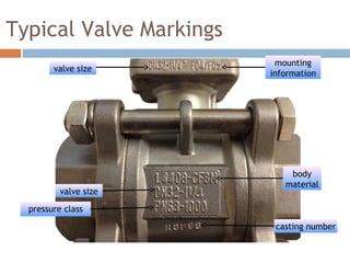
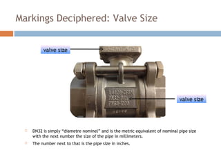
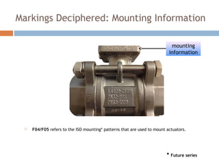
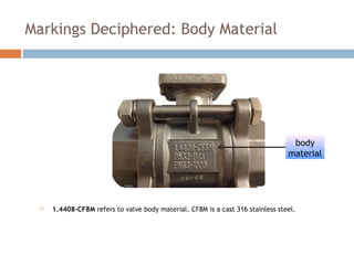
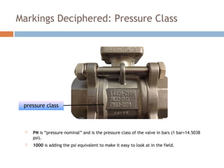
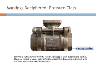
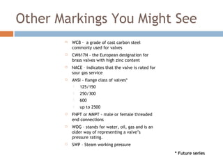
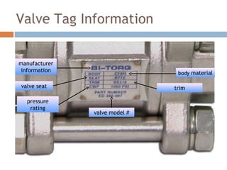
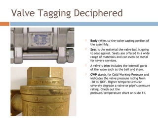
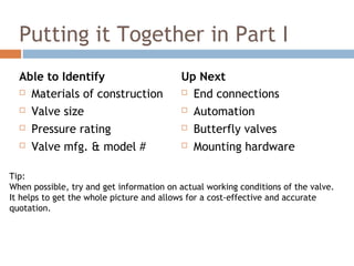
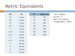
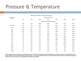
Identifying Valves for
Interchanges & Retrofits
Part I
Casting Markings & Tags on Ball Valves
2
Overview
 Valve markings
 Tagging information
 Marking & tagging deciphered
 Other needed information
 Metric equivalents
 Pressure & Temperature
3
Sound Familiar?
“Help, I need one of these…”
So how do you find out what “this” is?
Typical Valve Markings
valve size
body
material
valve size
pressure class
casting number
mounting
information
Markings Deciphered: Valve Size
 DN32 is simply “diametre nominel” and is the metric equivalent of nominal pipe size
with the next number the size of the pipe in millimeters.
 The number next to that is the pipe size in inches.
valve size
valve size
Markings Deciphered: Mounting Information
 F04/F05 refers to the ISO mounting* patterns that are used to mount actuators.
mounting
information
* Future series
Markings Deciphered: Body Material
 1.4408-CF8M refers to valve body material. CF8M is a cast 316 stainless steel.
body
material
Markings Deciphered: Pressure Class
 PN is “pressure nominal” and is the pressure class of the valve in bars (1 bar=14.5038
psi).
 1000 is adding the psi equivalent to make it easy to look at in the field.
pressure class
Markings Deciphered: Pressure Class
 R8F98 is a casting number from the foundry. It is used to track materials and batches.
These are needed to supply Material Test Reports (MTRs). Depending on the body style
there can be more than one of these marks.
casting number
Other Markings You Might See
 WCB - a grade of cast carbon steel
commonly used for valves
 CW617N - the European designation for
brass valves with high zinc content
 NACE – indicates that the valve is rated for
sour gas service
 ANSI - flange class of valves*
 125/150
 250/300
 600
 up to 2500
 FNPT or MNPT - male or female threaded
end connections
 WOG – stands for water, oil, gas and is an
older way of representing a valve’s
pressure rating.
 SWP – Steam working pressure
* Future series
11
Valve Tag Information
manufacturer
information body material
valve seat
pressure
rating
trim
valve model #
Valve Tagging Deciphered
 Body refers to the valve casting portion of
the assembly.
 Seat is the material the valve ball is going
to seal against. Seats are offered in a wide
range of materials and can even be metal
for severe services.
 A valve’s trim includes the internal parts
of the valve such as the ball and stem.
 CWP stands for Cold Working Pressure and
indicates the valve pressure rating from
-20 to 100F. Higher temperatures can
severely degrade a valve or pipe’s pressure
rating. Check out the
pressure/temperature chart on slide 11.
12
Putting it Together in Part I
Able to Identify
 Materials of construction
 Valve size
 Pressure rating
 Valve mfg. & model #
Up Next
 End connections
 Automation
 Butterfly valves
 Mounting hardware
Tip:
When possible, try and get information on actual working conditions of the valve.
It helps to get the whole picture and allows for a cost-effective and accurate
quotation.
Metric Equivalents
 1 bar = 14.058 psi
 25.4 mm = 1”
 Deg F = (C+17.78) X1.8
 1 kilopascal(kPa) = .145 psi
NPS DN
1/4" 8 mm
3/8" 10 mm
1/2" 15 mm
3/4" 20 mm
1" 25 mm
1-1/4" 32 mm
1-1/2" 40 mm
2" 50 mm
2-1/2" 65 mm
3" 80 mm
4" 100 mm
5" 125 mm
6" 150 mm
PN Flange Class
20 150
50 300
68 400
100 600
150 900
250 1500
420 2500
15
Maximum Allowable non-shock Pressure (psig)
Temperature
(o
F)
Pressure Class (lb)
150 300 400 600 900 1500 2500
Hydrostatic Test Pressure (psig)
450 1125 1500 2225 3350 5575 9275
-20 to 100 285 740 990 1480 2220 3705 6170
200 260 675 900 1350 2025 3375 5625
300 230 655 875 1315 1970 3280 5470
400 200 635 845 1270 1900 3170 5280
500 170 600 800 1200 1795 2995 4990
600 140 550 730 1095 1640 2735 4560
650 125 535 715 1075 1610 2685 4475
700 110 535 710 1065 1600 2665 4440
750 95 505 670 1010 1510 2520 4200
800 80 410 550 825 1235 2060 3430
850 65 270 355 535 805 1340 2230
900 50 170 230 345 515 860 1430
950 35 105 140 205 310 515 860
1000 20 50 70 105 155 260 430
Maximum allowable non-shock pressure (psig) and temperature ratings for steel pipe flanges and flanged fittings according the American National Standard ANSI
B16.5 - 1988. The values in this table apply to Material Group 1.1 (i.e. certain carbon steel grades). For other Material Groups the Pressure-Temperature Ratings are
different. Most carbon steels are only acceptable for temperatures below 800 F
Pressure & Temperature
Thank You
Contact us - sales@bitorq.com or 630-208-9343

Ball Valve Markings & Tags

  • 1.
    Identifying Valves for Interchanges& Retrofits Part I Casting Markings & Tags on Ball Valves
  • 2.
    2 Overview  Valve markings Tagging information  Marking & tagging deciphered  Other needed information  Metric equivalents  Pressure & Temperature
  • 3.
    3 Sound Familiar? “Help, Ineed one of these…” So how do you find out what “this” is?
  • 4.
    Typical Valve Markings valvesize body material valve size pressure class casting number mounting information
  • 5.
    Markings Deciphered: ValveSize  DN32 is simply “diametre nominel” and is the metric equivalent of nominal pipe size with the next number the size of the pipe in millimeters.  The number next to that is the pipe size in inches. valve size valve size
  • 6.
    Markings Deciphered: MountingInformation  F04/F05 refers to the ISO mounting* patterns that are used to mount actuators. mounting information * Future series
  • 7.
    Markings Deciphered: BodyMaterial  1.4408-CF8M refers to valve body material. CF8M is a cast 316 stainless steel. body material
  • 8.
    Markings Deciphered: PressureClass  PN is “pressure nominal” and is the pressure class of the valve in bars (1 bar=14.5038 psi).  1000 is adding the psi equivalent to make it easy to look at in the field. pressure class
  • 9.
    Markings Deciphered: PressureClass  R8F98 is a casting number from the foundry. It is used to track materials and batches. These are needed to supply Material Test Reports (MTRs). Depending on the body style there can be more than one of these marks. casting number
  • 10.
    Other Markings YouMight See  WCB - a grade of cast carbon steel commonly used for valves  CW617N - the European designation for brass valves with high zinc content  NACE – indicates that the valve is rated for sour gas service  ANSI - flange class of valves*  125/150  250/300  600  up to 2500  FNPT or MNPT - male or female threaded end connections  WOG – stands for water, oil, gas and is an older way of representing a valve’s pressure rating.  SWP – Steam working pressure * Future series
  • 11.
    11 Valve Tag Information manufacturer informationbody material valve seat pressure rating trim valve model #
  • 12.
    Valve Tagging Deciphered Body refers to the valve casting portion of the assembly.  Seat is the material the valve ball is going to seal against. Seats are offered in a wide range of materials and can even be metal for severe services.  A valve’s trim includes the internal parts of the valve such as the ball and stem.  CWP stands for Cold Working Pressure and indicates the valve pressure rating from -20 to 100F. Higher temperatures can severely degrade a valve or pipe’s pressure rating. Check out the pressure/temperature chart on slide 11. 12
  • 13.
    Putting it Togetherin Part I Able to Identify  Materials of construction  Valve size  Pressure rating  Valve mfg. & model # Up Next  End connections  Automation  Butterfly valves  Mounting hardware Tip: When possible, try and get information on actual working conditions of the valve. It helps to get the whole picture and allows for a cost-effective and accurate quotation.
  • 14.
    Metric Equivalents  1bar = 14.058 psi  25.4 mm = 1”  Deg F = (C+17.78) X1.8  1 kilopascal(kPa) = .145 psi NPS DN 1/4" 8 mm 3/8" 10 mm 1/2" 15 mm 3/4" 20 mm 1" 25 mm 1-1/4" 32 mm 1-1/2" 40 mm 2" 50 mm 2-1/2" 65 mm 3" 80 mm 4" 100 mm 5" 125 mm 6" 150 mm PN Flange Class 20 150 50 300 68 400 100 600 150 900 250 1500 420 2500
  • 15.
    15 Maximum Allowable non-shockPressure (psig) Temperature (o F) Pressure Class (lb) 150 300 400 600 900 1500 2500 Hydrostatic Test Pressure (psig) 450 1125 1500 2225 3350 5575 9275 -20 to 100 285 740 990 1480 2220 3705 6170 200 260 675 900 1350 2025 3375 5625 300 230 655 875 1315 1970 3280 5470 400 200 635 845 1270 1900 3170 5280 500 170 600 800 1200 1795 2995 4990 600 140 550 730 1095 1640 2735 4560 650 125 535 715 1075 1610 2685 4475 700 110 535 710 1065 1600 2665 4440 750 95 505 670 1010 1510 2520 4200 800 80 410 550 825 1235 2060 3430 850 65 270 355 535 805 1340 2230 900 50 170 230 345 515 860 1430 950 35 105 140 205 310 515 860 1000 20 50 70 105 155 260 430 Maximum allowable non-shock pressure (psig) and temperature ratings for steel pipe flanges and flanged fittings according the American National Standard ANSI B16.5 - 1988. The values in this table apply to Material Group 1.1 (i.e. certain carbon steel grades). For other Material Groups the Pressure-Temperature Ratings are different. Most carbon steels are only acceptable for temperatures below 800 F Pressure & Temperature
  • 16.
    Thank You Contact us- sales@bitorq.com or 630-208-9343