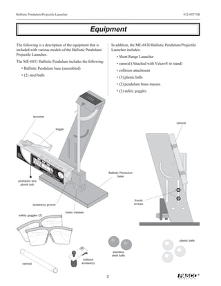
Downloaded 31 times


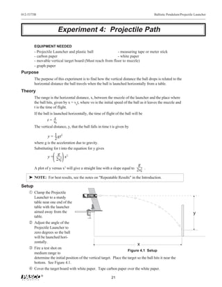


The PASCO ME-6830/ME-6831 Ballistic Pendulum/Projectile Launcher allows students to perform experiments on projectile motion and ballistic pendulums. Key features include the ability to launch balls at various angles from 0-90 degrees, three range settings, sights for aiming, and a spring-loaded ball catcher for the pendulum. The document provides instructions on general operation of the launcher including aiming, loading, shooting, and storing the device safely. Experiments outlined use the device to investigate projectile motion, conservation of energy, momentum, and more.


