Download to read offline


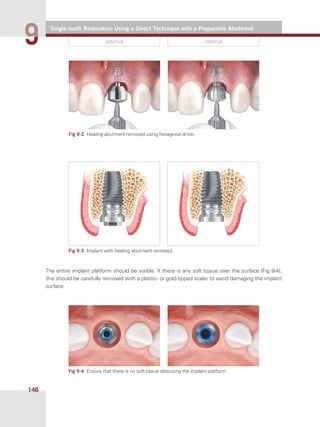
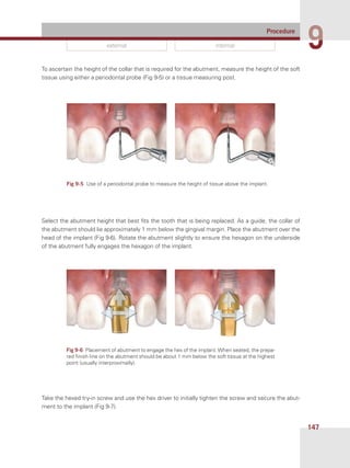

This document provides instructions for performing a direct single-tooth restoration using a preparable abutment. It describes removing the healing abutment to expose the implant platform, measuring the soft tissue height, selecting an abutment with the appropriate collar height, placing the abutment on the implant and initially tightening it with a try-in screw. The goal is to have the abutment collar sit 1 mm below the gingival margin to allow for cement.


![NEW dental implant design [Autosaved].pptx](https://cdn.slidesharecdn.com/ss_thumbnails/newimplantdesignautosaved-250614065418-013f8c1f-thumbnail.jpg?width=640&height=640&fit=bounds)


