This document provides an introduction to network layer concepts. It discusses:
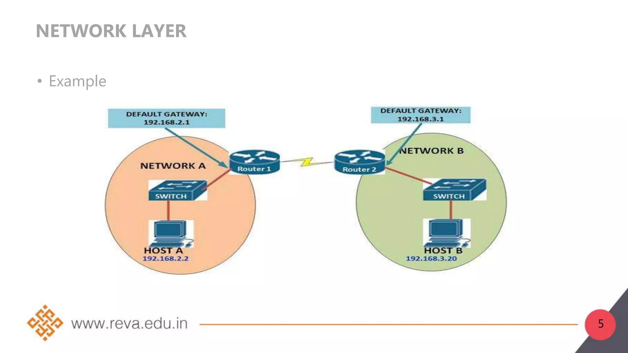
1. The network layer is layer 3 of the OSI model and is responsible for logical addressing, internetworking, and routing packets from source to destination.
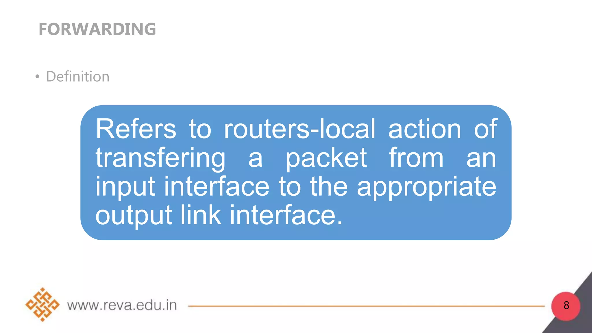
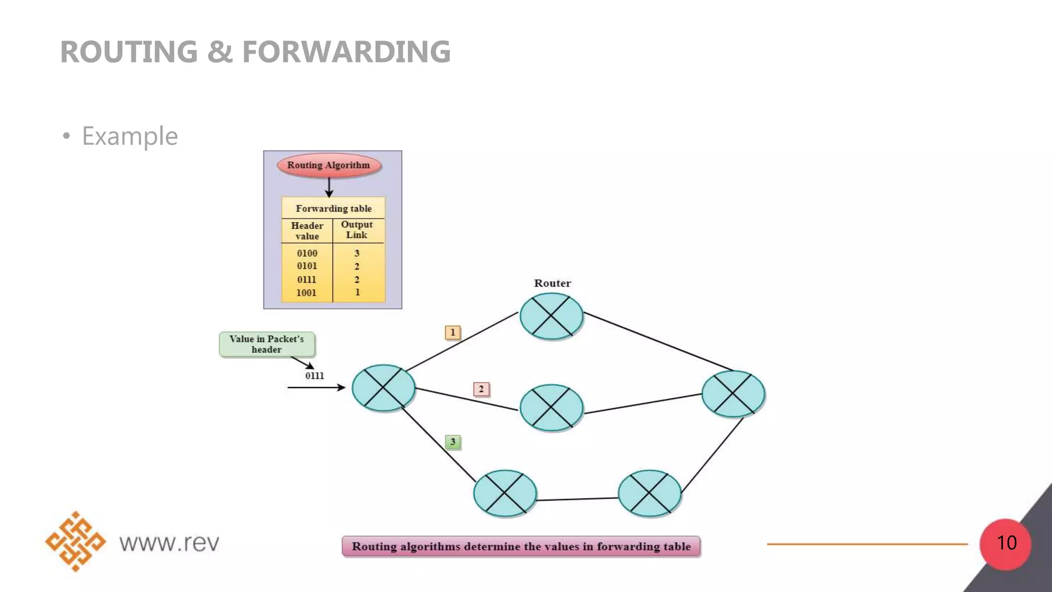
2. Network layer functions include forwarding, routing, logical addressing, connection setup, and fragmentation/defragmentation. Forwarding refers to transferring packets between interfaces on a router, while routing determines the optimal end-to-end path between sources and destinations.
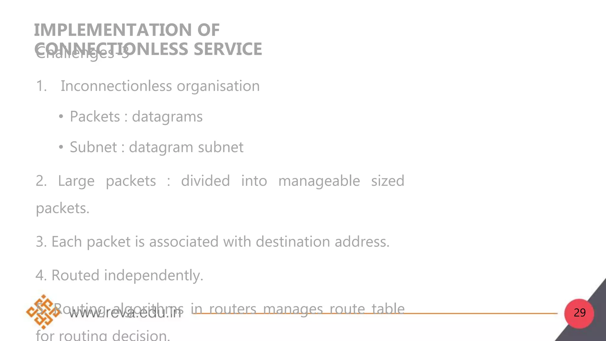
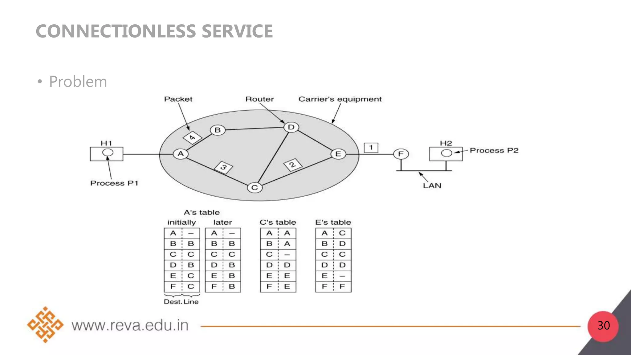
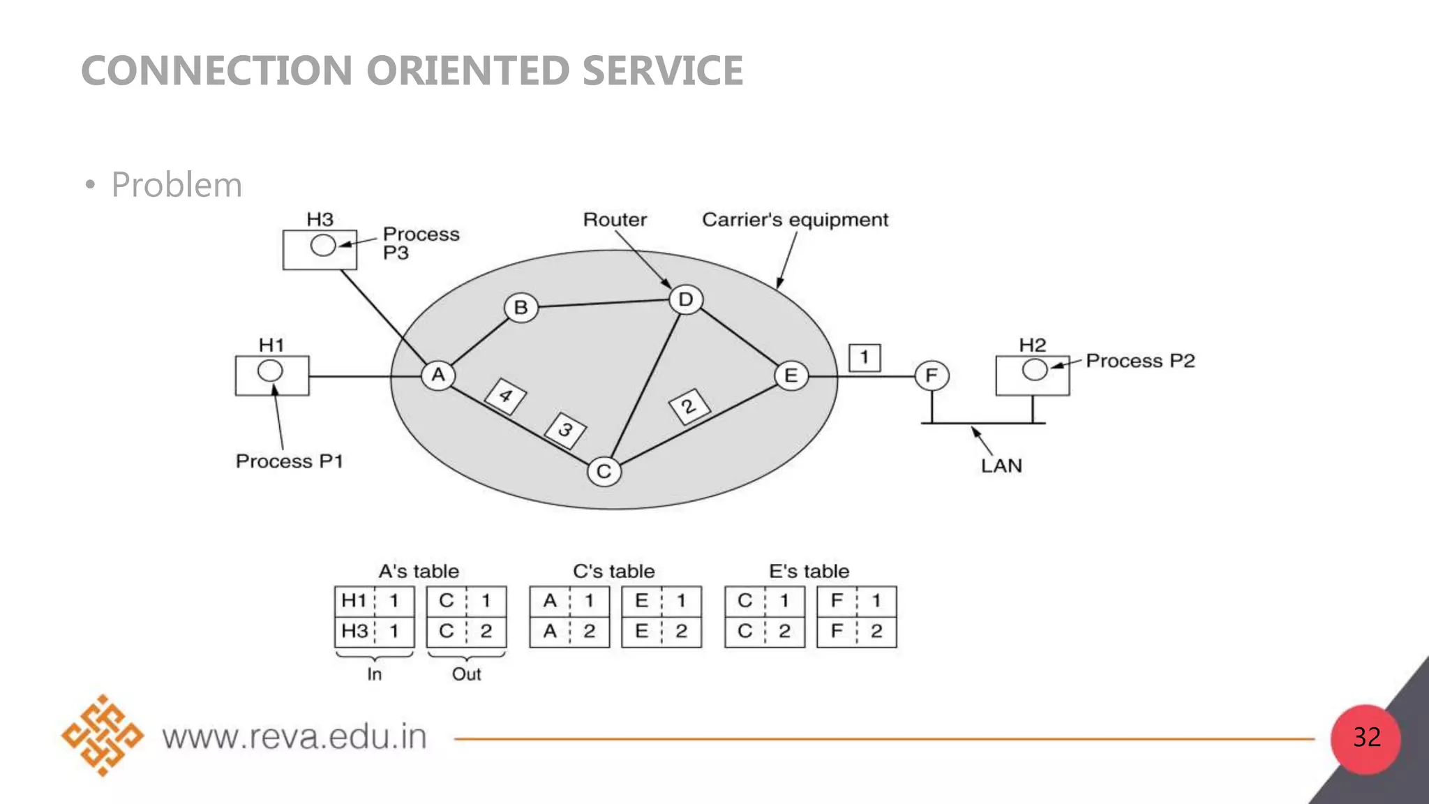
3. Network layer services can be connection-oriented using virtual circuits, which guarantee delivery properties, or connectionless using datagrams, which provide only best effort delivery. Common virtual circuit networks are ATM and Frame Relay,


![DIJKSTRA ALGORITHM:
Slide-1
function Dijkstra(Graph, source):
create vertex set Q
for each vertex v in Graph:
dist[v] ← INFINITY
prev[v] ← UNDEFINED
add v to Q
dist[source] ← 0
69](https://image.slidesharecdn.com/b21da020103-230703084520-b9ddd1ca/75/B21DA0201_03-ppt-69-2048.jpg)
![DIJKSTRA ALGORITHM:
Slide-2
while Q is not empty:
u ← vertex in Q with min dist[u]
remove u from Q
for each neighbor v of u: // only v that are
still in Q
alt ← dist[u] + length(u, v)
if alt < dist[v]:
dist[v] ← alt
prev[v] ← u
return dist[], prev[]
70](https://image.slidesharecdn.com/b21da020103-230703084520-b9ddd1ca/75/B21DA0201_03-ppt-70-2048.jpg)


![Unit-3-Part-1 [Autosaved].ppt](https://cdn.slidesharecdn.com/ss_thumbnails/unit-3-part-1autosaved-230216062941-16596250-thumbnail.jpg?width=640&height=640&fit=bounds)