The document describes various aspects of network layer design and routing algorithms. It discusses:
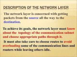
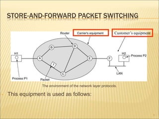
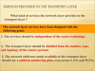
1. The key responsibilities of the network layer in getting packets from source to destination.
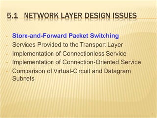
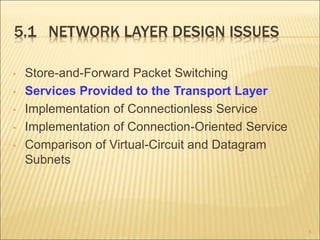
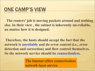
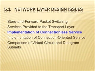
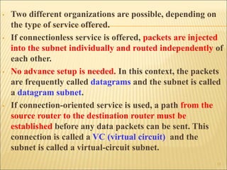
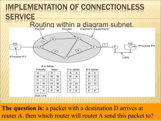
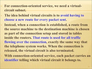
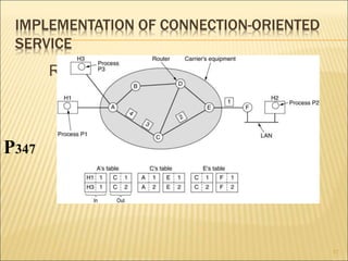
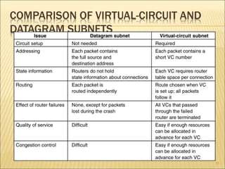
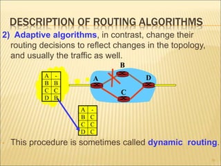
2. The two main approaches to network layer service - connectionless and connection-oriented. This includes the implementation and tradeoffs of each.
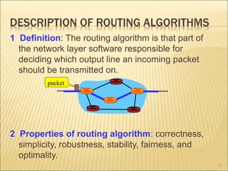
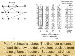
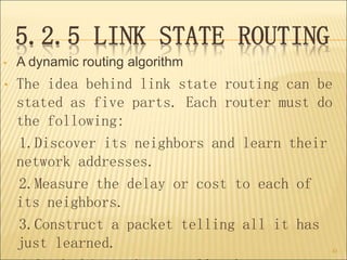
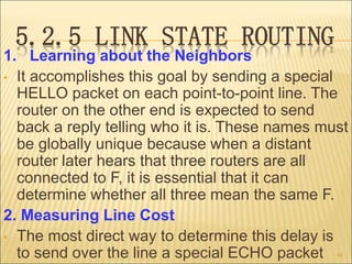
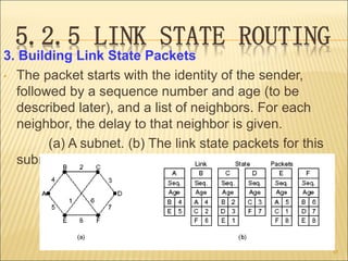
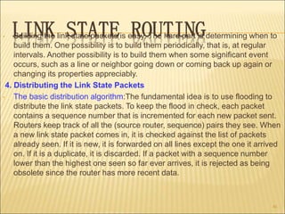
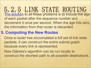
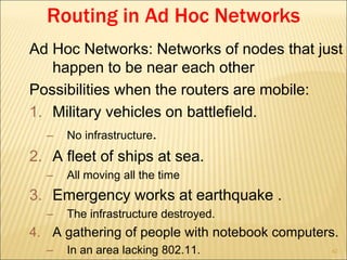
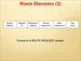
3. Several routing algorithms used at the network layer like flooding, distance vector, and link state routing. It explains how these algorithms work and their advantages.


![Unit-3-Part-1 [Autosaved].ppt](https://cdn.slidesharecdn.com/ss_thumbnails/unit-3-part-1autosaved-230216062941-16596250-thumbnail.jpg?width=640&height=640&fit=bounds)