This document summarizes the American Water Works Association (AWWA) standard for vertical turbine pumps, including both line-shaft and submersible types. It provides definitions, specifications, engineering data, and requirements for factory inspection and testing of vertical turbine pumps. The standard is intended to guide the procurement of vertical turbine pumps for water service and provide options that must be evaluated by the user. It also contains appendices on field testing pumps and a suggested specification form for purchase. The major revisions to this 1988 standard included adding provisions for solid shaft motors in 1977 and various editorial changes and conversions to metric units.
![American Water Works Association
ANSI/AWWA E101-88
(Revision of ANSI/AWWA E101-77 [R82])
AWWA STANDARD
FOR
VERTICAL TURBINE PUMPS— LINE SHAFT
AND SUBMERSIBLE TYPES
Effective date: Aug. 1, 1988.
First edition approved by AWWA Board of Directors May 11, 1955.
This edition approved Jan. 24, 1988.
Approved by American National Standards Institute May 31, 1988.
AMERICAN WATER WORKS ASSOCIATION
6666 West Quincy Avenue, Denver, Colorado 80235
R
Copyright (C) 1998 American Water Works Association, All Rights Reserved.](https://image.slidesharecdn.com/awwa-e-101-vertical-turbine-pumps-230508125022-d0c2d44c/75/AWWA-E-101-Vertical-Turbine-Pumps-pdf-1-2048.jpg)


![American Water Works Association
AWWA E101-88
(Revision of ANSI/AWWA E101-77 [R82])
AWWA STANDARD FOR
VERTICAL TURBINE PUMPS— LINE
SHAFT AND SUBMERSIBLE TYPES
Part A— Line-Shaft Vertical Turbine Pumps
SECTION A-1: SCOPE AND PURPOSE
Part A of this standard provides minimum requirements for line-shaft vertical
turbine pumps utilizing discharge column pipe up to and including 16 in. (400 mm)
in size. The standard deals with a pump configuration up to and including the
driver. Only electric motors are referred to as prime movers.
Purchasers who intend to use the pumps for pumping liquids other than clear,
cold water should modify the requirements to fit conditions of intended use, prefer-
ably after consultation with pump manufacturers.
SECTION A-2: DEFINITIONS
A-2.1 Line-shaft vertical turbine pump: A vertical-shaft centrifugal or mixed-
flow pump with rotating impeller or impellers, and with discharge from the pump-
ing element coaxial with the shaft. The pumping element is suspended by the con-
ductor system, which encloses a system of vertical shafting used to transmit power
to the impellers, the prime mover being external to the flow stream.
A-2.2 Pump: For purposes of this standard, a pump may be defined as a de-
vice used to provide energy for initiating or maintaining the movement of liquid. A
pump consists of three elements, defined as follows:
1
R
Copyright (C) 1998 American Water Works Association, All Rights Reserved.](https://image.slidesharecdn.com/awwa-e-101-vertical-turbine-pumps-230508125022-d0c2d44c/75/AWWA-E-101-Vertical-Turbine-Pumps-pdf-9-2048.jpg)


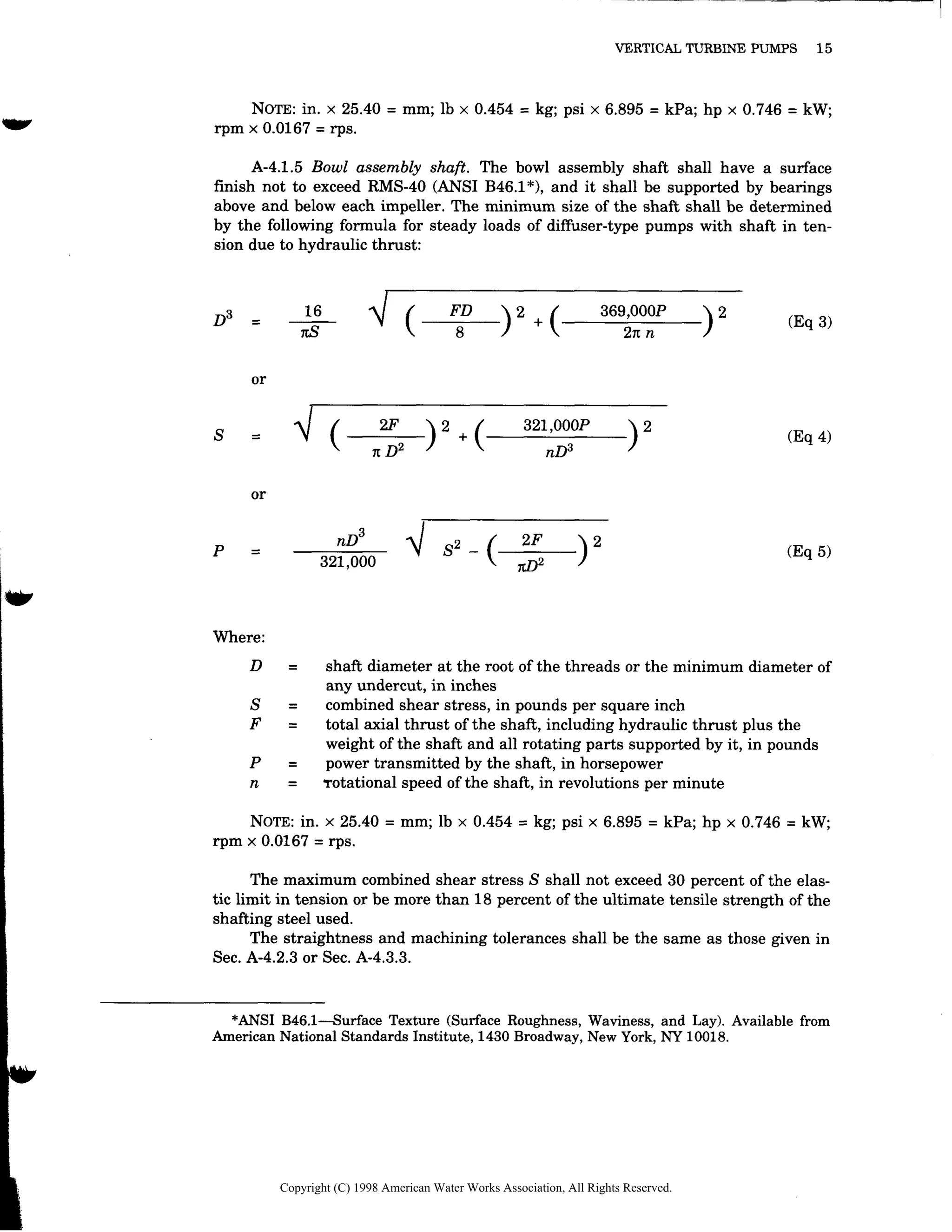
![proper size to drive the pump continuously over the specified operating range with-
out the load exceeding the nameplate rating of the motor. The motor shall be rated
as drip proof with class B insulation and with a 1.15 service factor.
With an engine drive, the power shall be applied to the pump shaft through a
right-angle gear drive. The connection to the vertical shaft shall be through a cou-
pling or clutch in the gear head. The horizontal shaft shall rotate in the same direc-
tion as the engine drive, and shall be connected to the engine by a flexible shaft
coupling.
An optional method of driving, for an engine or horizontal electric motor, shall
be a belted drive—either a flat belt on a modified cylindrical pulley or a V-belt on a
V-groove pulley.
Rotation of the vertical shaft shall be counterclockwise when viewed from
above.
A thrust bearing of ample capacity to carry the weight of all rotating parts plus
the hydraulic thrust at maximum operating conditions shall be incorporated into the
driver. For antifriction bearings, the bearings shall be of such capacity that the
AFBMA* calculated rating life (L10) shall be no less than 8800 h. If the design and
operating conditions are such that upthrust can occur, then proper provisions shall
be made to accommodate the upthrust. This shall be done by the supplier.
A-4.1.3 Suction pipe and strainer. A strainer, if required, shall have a net in-
let area equal to at least three times the suction pipe area. The maximum opening
shall not be more than 75 percent of the minimum opening of the water passage
through the bowl or impeller.
A-4.1.4 Shaft couplings. Line shafts shall be coupled with steel couplings that
shall have a left-hand thread to tighten during pump operation. The maximum com-
bined shear stress, determined by the following formula, shall not exceed 20 percent
of the elastic limit in tension nor be more than 12 percent of the ultimate tensile
strength of the shafting steel used.
————————————————————————————
2F 321,000P
S = √ [ —————————]2
+ [—————————]2
(Eq 2)
π (D2
– d2
) n (D3
– d3
)
Where:
S = combined shear stress, in pounds per square inch
F = total axial thrust of the shaft, including hydraulic thrust plus the
weight of the shaft and all rotating parts supported by it, in pounds
D = outside diameter of the coupling, in inches
d = inside diameter of the coupling at the root of the threads, in inches
P = power transmitted by the shaft, in horsepower
n = rotational speed of the shaft, in revolutions per minute
14 AWWA E101-88
*Anti-Friction Bearing Manufacturers Association, 1101 Connecticut Ave. N.W., Suite 700,
Washington, DC 20036.
Copyright (C) 1998 American Water Works Association, All Rights Reserved.](https://image.slidesharecdn.com/awwa-e-101-vertical-turbine-pumps-230508125022-d0c2d44c/75/AWWA-E-101-Vertical-Turbine-Pumps-pdf-22-2048.jpg)