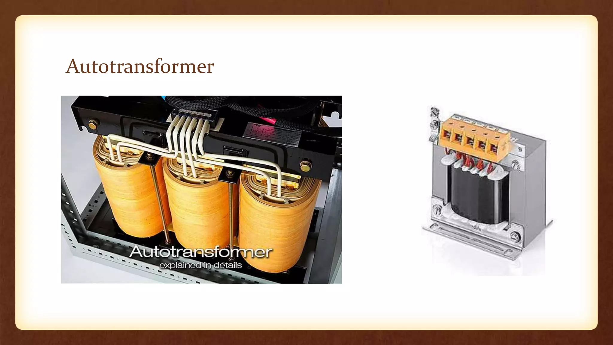
Autotransformer
Autotransformer
• Construction
• Principle of Operation
• Application
• Comparing and contrasting with the two winding transformer
Autotransformer
Construction
the copper wire is wound on a laminated silicon steel core, with at least three
tapping taken out.
the primary and secondary windings are linked together both electrically and
magnetically.
It consists of a single copper wire which is common to both primary and
secondary coil.
Secondary and primary circuit share the same neutral point of the winding.
 it changes the voltage by small amount thus a single winding is used to reduce
the expense of constructing two windings of approximately same number of
turns.
Continuation
Variable turns ratio at secondary can be obtained by tapping of the
windings, or by providing a smooth sliding brush over the winding.
The main advantage of this type of transformer design is that it can be
made a lot cheaper for the same VA rating.
Types of Autotransformer
L 1,L2,L3 Live
N Neutral
N1,N₂,N3 Number of turns in
secondary coil
Np Number of turns in
primary coil
Vs1,Vs2,Vs3 Voltage across
secondary coil
V p Voltage across primary
coil
Variable Autotransformer (Variac)
Variable Autotransformer
Types of Autotransformer
Principle of Operation
o The primary voltage is applied across two of the terminals, and the
secondary voltage taken from two terminals, almost always having one
terminal in common with the primary voltage.
o The primary and secondary circuits therefore have a number of
windings turns in common. Since the volts-per-turn is the same in
both windings, each develops a voltage in proportion to its number of
turns.
o In an autotransformer part of the current flows directly from the input
to the output, and only part is transferred inductively, allowing a
smaller, lighter, cheaper core to be used as well as requiring only a
single winding.
Principle of operation
• An auto transformer has only one winding which is shared by both primary and
secondary circuit, where number of turns shared by secondary are variable.
• EMF induced in the winding is proportional to the number of turns. Therefore,
the secondary voltage can be varied by just changing secondary number of turns.
• Most of the energy is transferred by means of electrical conduction and a small
part through induction.
• A transformer in which Np>Ns is called a step down transformer. A step down
transformer is a transformer which converts high alternating voltage to low alternating
voltage.
• A transformer in which Ns>Np is called a step up transformer. A step up
transformer is a transformer which converts low alternative voltage to high alternative
voltage.
• When the primary current IP is flowing through the single winding in the direction of the arrow as
shown, the secondary current, IS, flows in the opposite direction. Therefore, in the portion of the
winding that generates the secondary voltage, VS the current flowing out of the winding is the
difference of IP and IS.
From the diagram the following equation can be
deduced:
𝑽𝒔
𝑽𝒑
= 𝑵𝒔
𝑵𝒔+(𝑵𝒑−𝑵𝒔)
𝑰𝒔
𝑰𝒑
=
𝑵𝒔+(𝑵𝒑−𝑵𝒔)
𝑵𝒔
Application
Autotransformers are used to compensate for voltage drops in transmission
and distribution lines. When used for this purpose, they are known as
booster transformers.
Autotransformers are used for reducing the voltage supplied to a.c motors
during the starting period.
Autotransformers are used for continuously variable supply.
On long rural power distribution lines, special autotransformers with
automatic tap-changing equipment are inserted as voltage regulators, so that
customers at the far end of the line receive the same average voltage as
those closer to the source. The variable ratio of the autotransformer
compensates for the voltage drop along the line.
Continuation
 In audio applications, tapped autotransformers are used to adapt
speakers to constant-voltage audio distribution systems, and for
impedance matching such as between a low-impedance microphone
and a high-impedance amplifier input.
can be used to transform voltages when the primary to secondary ratio
is close to unity.
Contrasting between autotransformer and two winding
transformer
• Both use the principle of induction.
Comparing autotransformer with two winding
transformer
Autotransformer Two winding transformer
-one single winding is used as primary winding as well as
secondary winding
-two different windings are used for primary and
secondary purpose.
-the output voltage for a given constant input voltage can
be varied from zero to the maximum level by simply
varying the number of secondary turns
-the output voltage can be varied only by varying the
input voltage or by tap changing
-energy transfer occurs by both conduction and
induction.
-energy transfer is only through induction.
-is more efficient and economical than its two winding
counterpart.
-less efficient than auto transformers.
-Winding material requirement is less -winding material requirement is more.
-Load connected to the auto transformer is electrically
connected with the source.
-load connected to the auto transformer is electrically
isolated from the source
-Wide range of voltage variation is possible -only a small variation of output voltage for a given input
voltage is possible.
END

Autotransformer.pptx

  • 1.
  • 2.
    Autotransformer • Construction • Principleof Operation • Application • Comparing and contrasting with the two winding transformer
  • 3.
  • 4.
    Construction the copper wireis wound on a laminated silicon steel core, with at least three tapping taken out. the primary and secondary windings are linked together both electrically and magnetically. It consists of a single copper wire which is common to both primary and secondary coil. Secondary and primary circuit share the same neutral point of the winding.  it changes the voltage by small amount thus a single winding is used to reduce the expense of constructing two windings of approximately same number of turns.
  • 5.
    Continuation Variable turns ratioat secondary can be obtained by tapping of the windings, or by providing a smooth sliding brush over the winding. The main advantage of this type of transformer design is that it can be made a lot cheaper for the same VA rating.
  • 6.
    Types of Autotransformer L1,L2,L3 Live N Neutral N1,N₂,N3 Number of turns in secondary coil Np Number of turns in primary coil Vs1,Vs2,Vs3 Voltage across secondary coil V p Voltage across primary coil Variable Autotransformer (Variac)
  • 7.
  • 8.
  • 9.
    Principle of Operation oThe primary voltage is applied across two of the terminals, and the secondary voltage taken from two terminals, almost always having one terminal in common with the primary voltage. o The primary and secondary circuits therefore have a number of windings turns in common. Since the volts-per-turn is the same in both windings, each develops a voltage in proportion to its number of turns. o In an autotransformer part of the current flows directly from the input to the output, and only part is transferred inductively, allowing a smaller, lighter, cheaper core to be used as well as requiring only a single winding.
  • 10.
    Principle of operation •An auto transformer has only one winding which is shared by both primary and secondary circuit, where number of turns shared by secondary are variable. • EMF induced in the winding is proportional to the number of turns. Therefore, the secondary voltage can be varied by just changing secondary number of turns. • Most of the energy is transferred by means of electrical conduction and a small part through induction. • A transformer in which Np>Ns is called a step down transformer. A step down transformer is a transformer which converts high alternating voltage to low alternating voltage. • A transformer in which Ns>Np is called a step up transformer. A step up transformer is a transformer which converts low alternative voltage to high alternative voltage.
  • 11.
    • When theprimary current IP is flowing through the single winding in the direction of the arrow as shown, the secondary current, IS, flows in the opposite direction. Therefore, in the portion of the winding that generates the secondary voltage, VS the current flowing out of the winding is the difference of IP and IS. From the diagram the following equation can be deduced: 𝑽𝒔 𝑽𝒑 = 𝑵𝒔 𝑵𝒔+(𝑵𝒑−𝑵𝒔) 𝑰𝒔 𝑰𝒑 = 𝑵𝒔+(𝑵𝒑−𝑵𝒔) 𝑵𝒔
  • 12.
    Application Autotransformers are usedto compensate for voltage drops in transmission and distribution lines. When used for this purpose, they are known as booster transformers. Autotransformers are used for reducing the voltage supplied to a.c motors during the starting period. Autotransformers are used for continuously variable supply. On long rural power distribution lines, special autotransformers with automatic tap-changing equipment are inserted as voltage regulators, so that customers at the far end of the line receive the same average voltage as those closer to the source. The variable ratio of the autotransformer compensates for the voltage drop along the line.
  • 13.
    Continuation  In audioapplications, tapped autotransformers are used to adapt speakers to constant-voltage audio distribution systems, and for impedance matching such as between a low-impedance microphone and a high-impedance amplifier input. can be used to transform voltages when the primary to secondary ratio is close to unity.
  • 14.
    Contrasting between autotransformerand two winding transformer • Both use the principle of induction.
  • 15.
    Comparing autotransformer withtwo winding transformer Autotransformer Two winding transformer -one single winding is used as primary winding as well as secondary winding -two different windings are used for primary and secondary purpose. -the output voltage for a given constant input voltage can be varied from zero to the maximum level by simply varying the number of secondary turns -the output voltage can be varied only by varying the input voltage or by tap changing -energy transfer occurs by both conduction and induction. -energy transfer is only through induction. -is more efficient and economical than its two winding counterpart. -less efficient than auto transformers. -Winding material requirement is less -winding material requirement is more. -Load connected to the auto transformer is electrically connected with the source. -load connected to the auto transformer is electrically isolated from the source -Wide range of voltage variation is possible -only a small variation of output voltage for a given input voltage is possible.
  • 16.