Download to read offline

![2
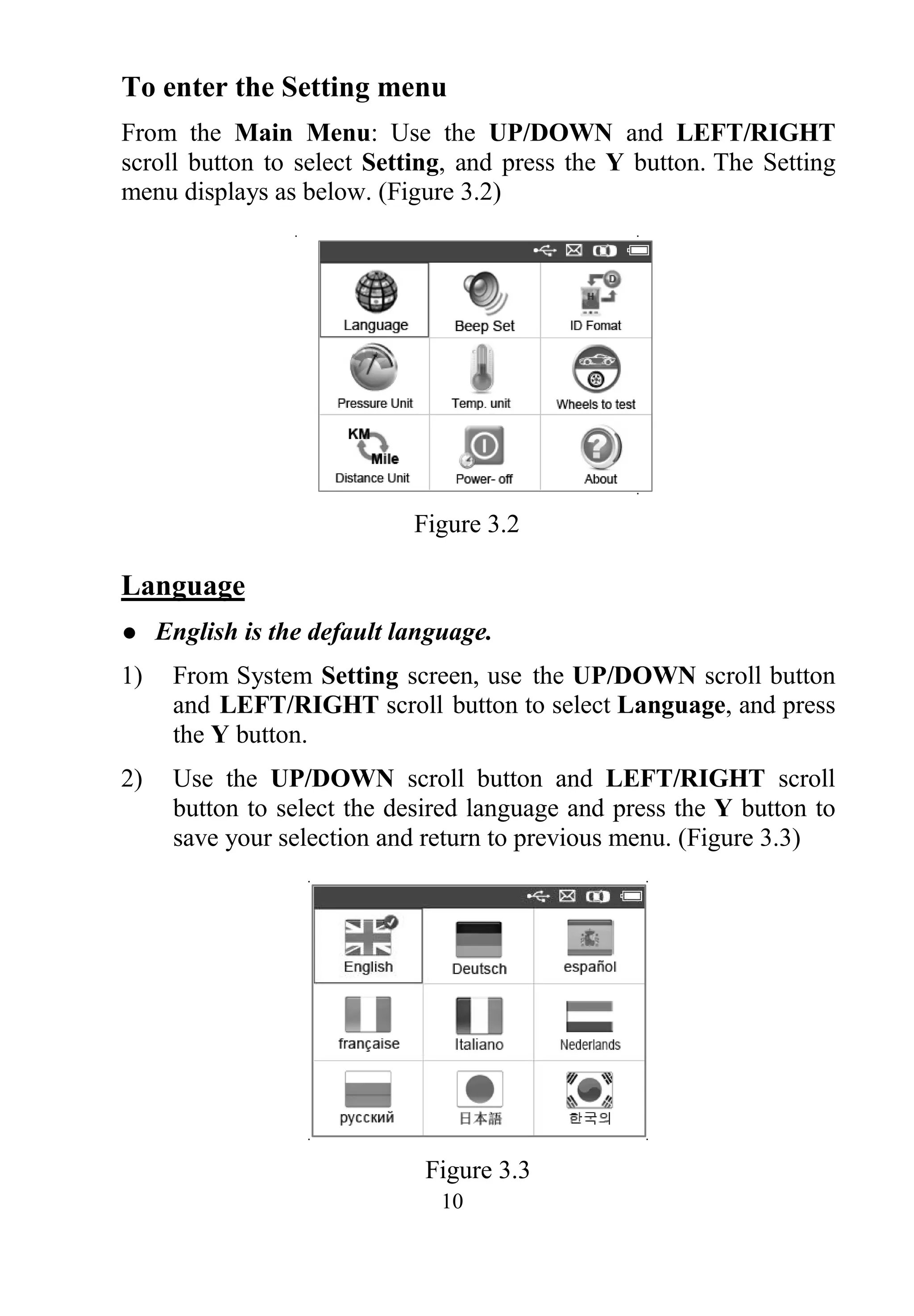
2. General Information
2.1 TPMS System Review
A tire pressure monitoring system (TPMS) is an electronic system
designed to monitor the air pressure inside the pneumatic tires on
various types of vehicles. TPMS report real-time tire-pressure
information to the driver of the vehicle, either via a gauge, a
pictogram display, or a simple low-pressure warning light. TPMS
can be divided into two different types — direct (dTPMS) and
indirect (iTPMS). TPMS are provided both at an OEM (factory)
level as well as an aftermarket solution.
2.2 TPMS Legislation
In the United States, the United States Department of Transportation
(NHTSA) released the FMVSS No. 138, w hich requires an
installation of a Tire Pressure Monitoring System to all new
passenger cars, multipurpose passenger vehicles, trucks, and buses
that have a gross vehicle weight rating (GVWR) of 4,536 kg
(10,000 lbs.) or less, except those vehicles with dual wheels on an
axle, as of 2007. In the European Union, starting November 1, 2012,
all new models of passenger cars must be equipped with a TPMS,
with even tighter specifications that will be defined by the UNECE
Vehicle Regulations (Regulation No. 64). From November 1, 2014,
all new passenger cars sold in the European Union must be equipped
with TPMS. On July 13, 2010, the South Korean Ministry of Land,
Transport and Maritime Affairs announced a pending partial-revision
to the Korea Motor Vehicle Safety Standards (KMVSS), specifying
that "TPMS shall be installed to passenger vehicles and vehicles of
GVW 3.5 tons or less, ... [effective] on J anuary 1, 2013 f or new
models and on June 30, 2014 for existing models". Japan is expected
to adopt European Union legislation approximately one year after
European Union implementation. Further countries to make TPMS
mandatory include Russia, Indonesia, the Philippines, Israel,
Malaysia and Turkey.](https://image.slidesharecdn.com/autelmaxitpmsts501professional-190114152900/75/Autel-TS501-User-Manual-4-2048.jpg)

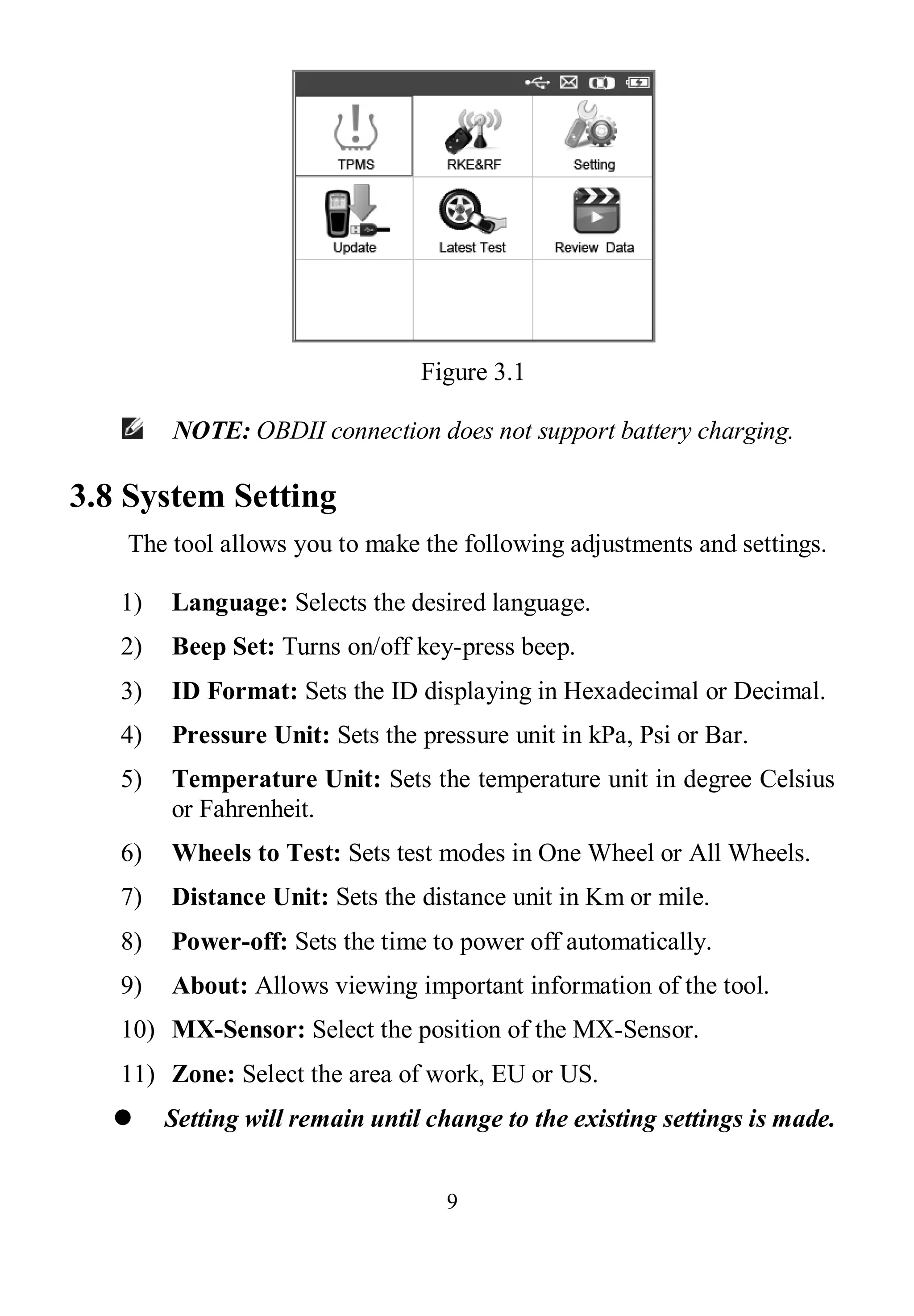
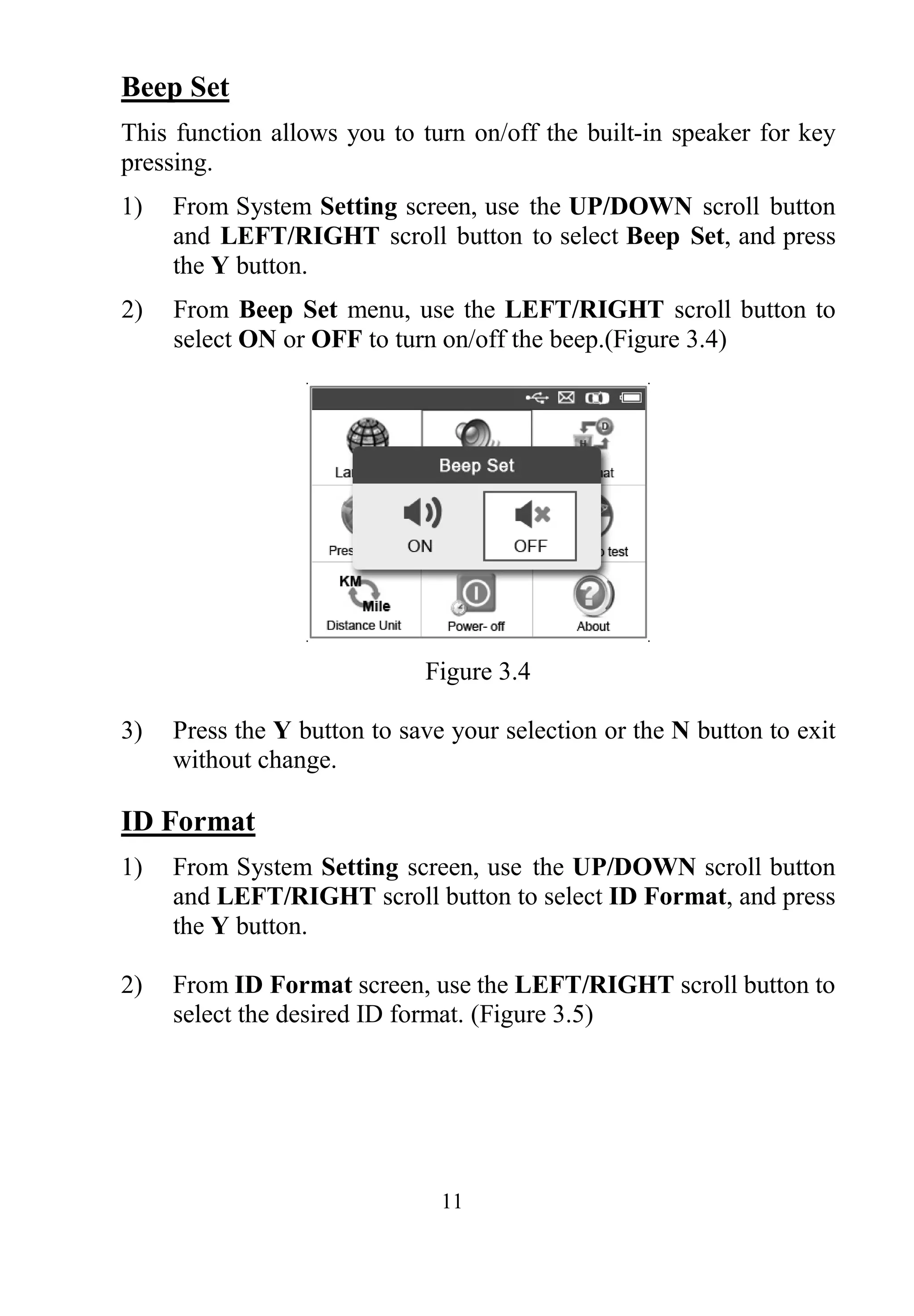
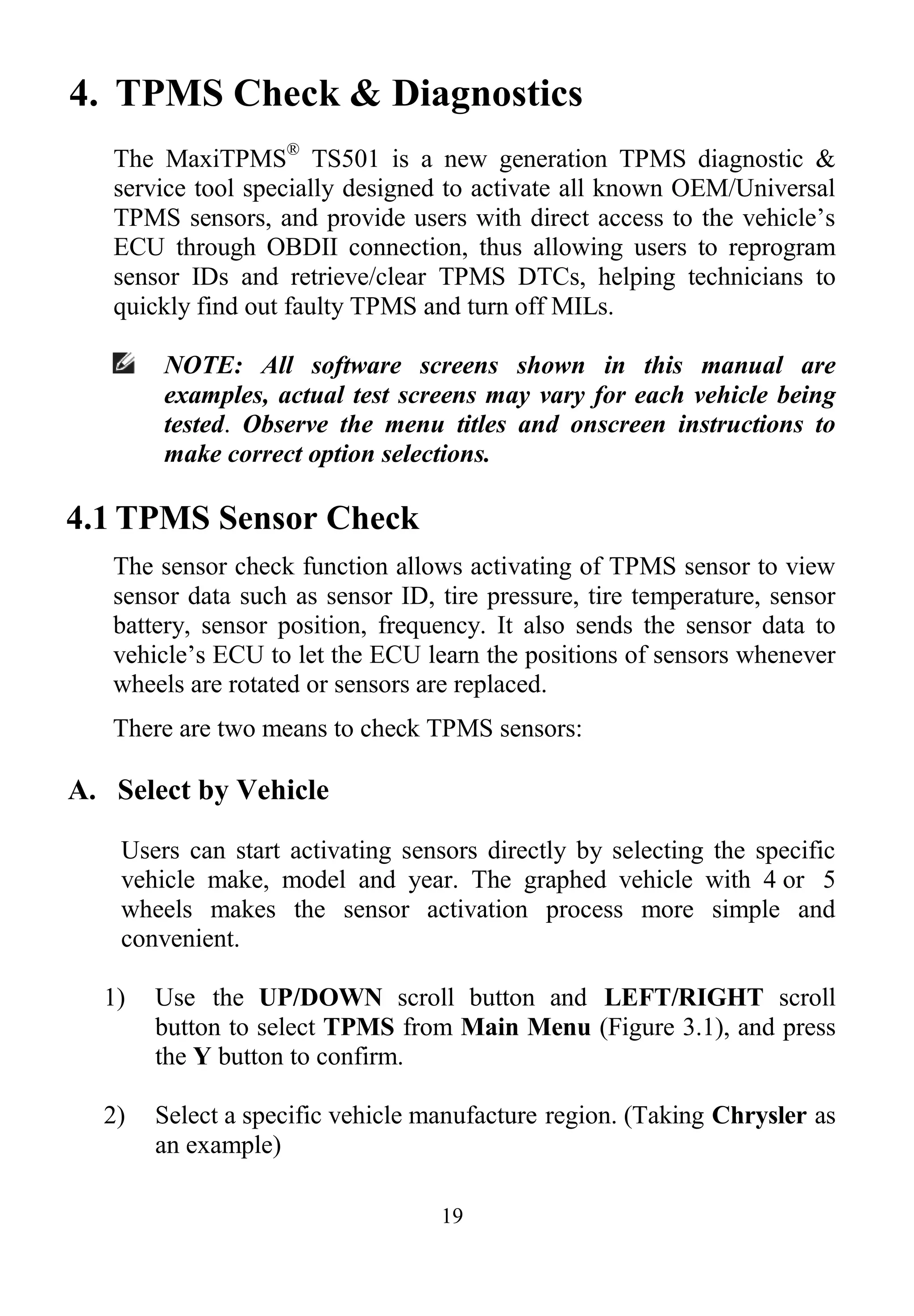


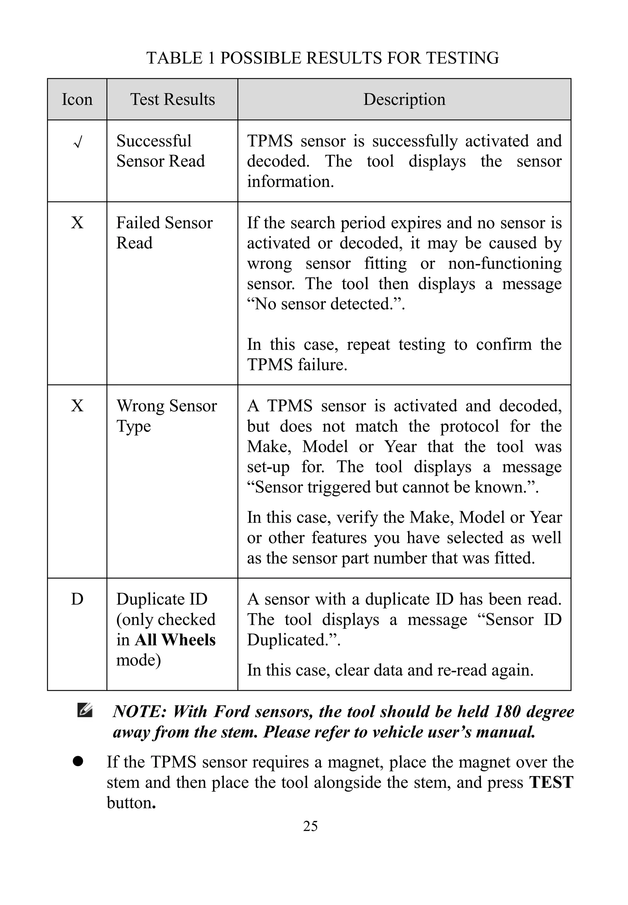

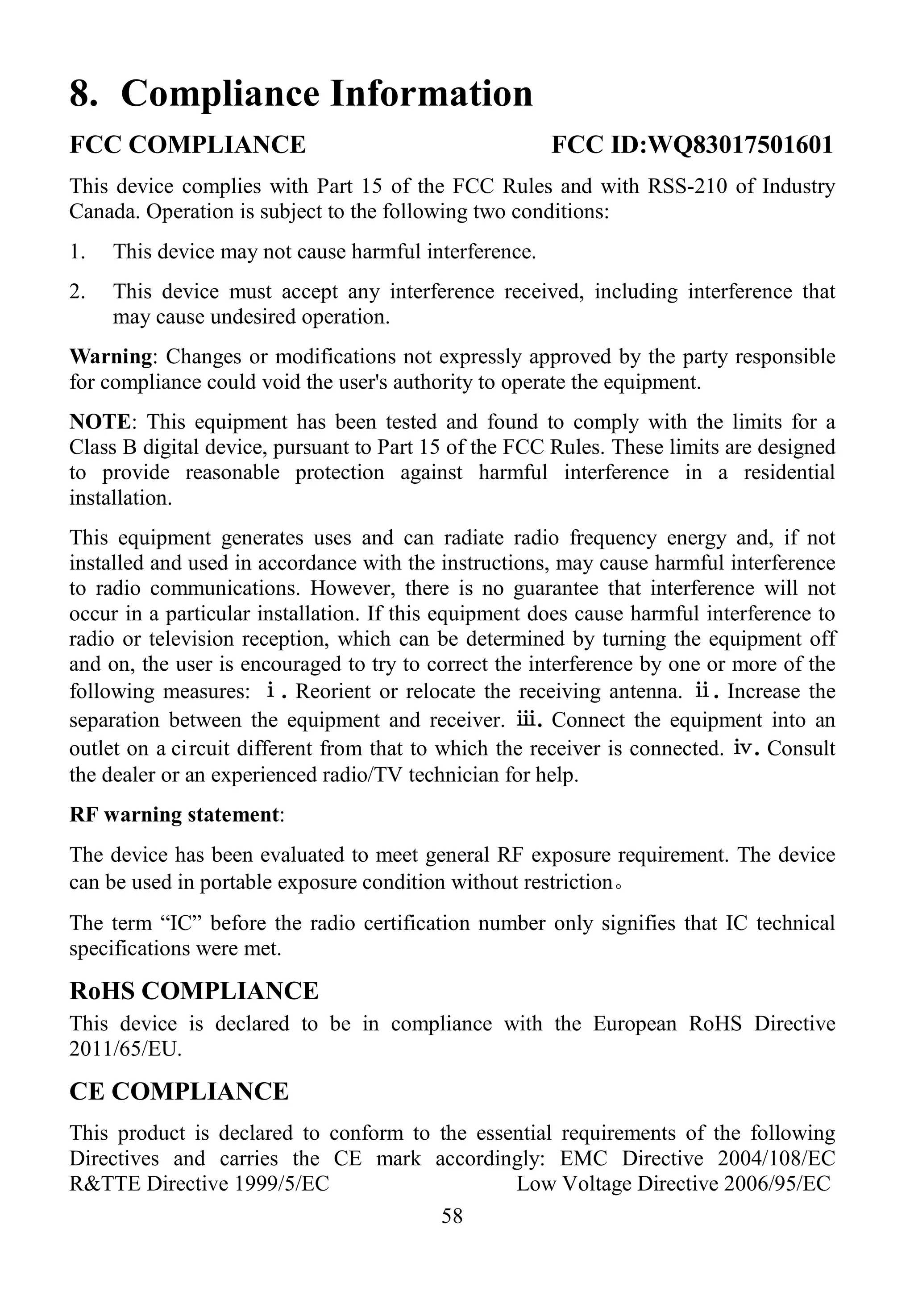
![28
[Pos] – Indicates the wheel sensor position.
[ID-H/D] – Shows sensor ID data.
[KPa/Psi/Bar] – Indicates tire pressure.
[°C/°F] – Indicates tire temperature.
[BAT] – Indicates battery condition.
[Mode] – Defines tire sensor working mode or status.
[Modulation] – Indicates sensor signal amplitude.
Different ID format, pressure and temperature units will display
at the title bar according to the device’s system setting, please
refer to 3.8 System Setting for detailed instruction.
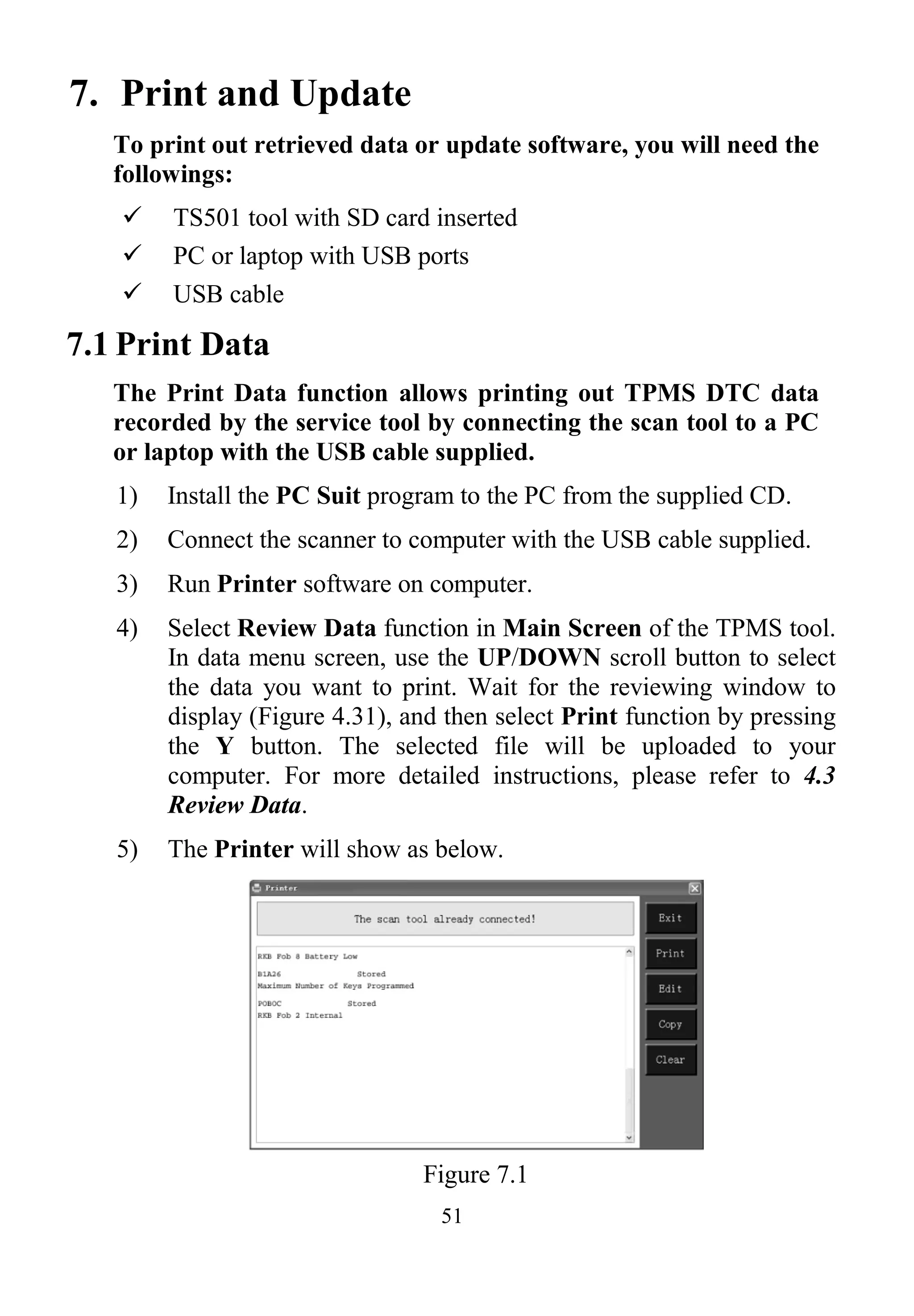
B. Select by latest test
This function allows you to review the last tested sensor data and
activate the sensor by using the wave signal of the latest trigger event,
which is very convenient and useful for technicians to wake up
sensors of the same vehicle.
1) Use the UP/DOWN scroll button and LEFT/RIGHT scroll
button to select Latest Test from Main Menu (Figure 3.1).
2) An activation screen with the previously activated sensor
information will show up (Figure 4.17). Use the UP/DOWN or
LEFT/RIGHT scroll button to select the desired wheel, and
press the TEST button to reactivate the sensor, or press the Y
button to view all detailed sensor data (Figure 4.18).
Figure 4.17](https://image.slidesharecdn.com/autelmaxitpmsts501professional-190114152900/75/Autel-TS501-User-Manual-30-2048.jpg)


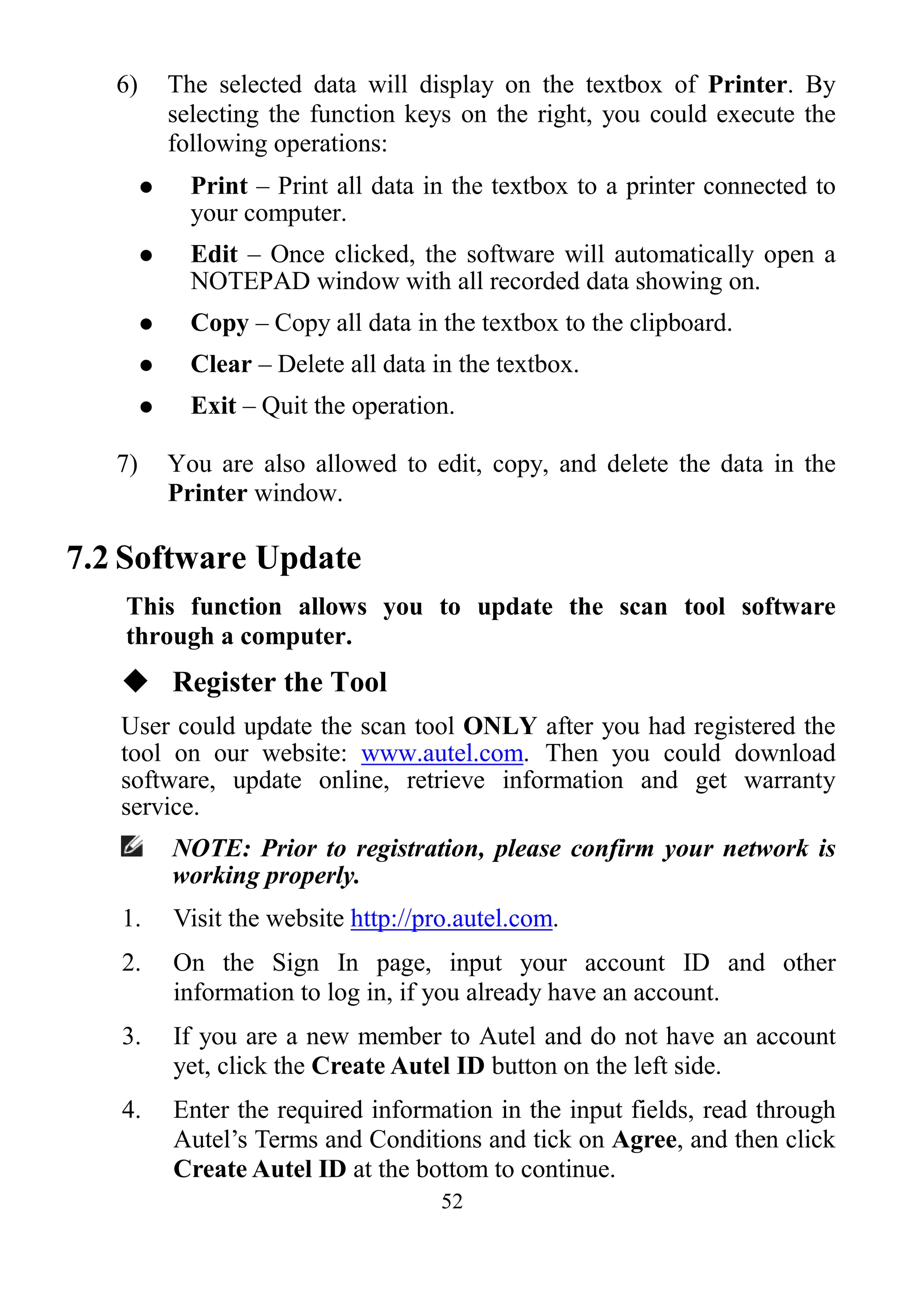
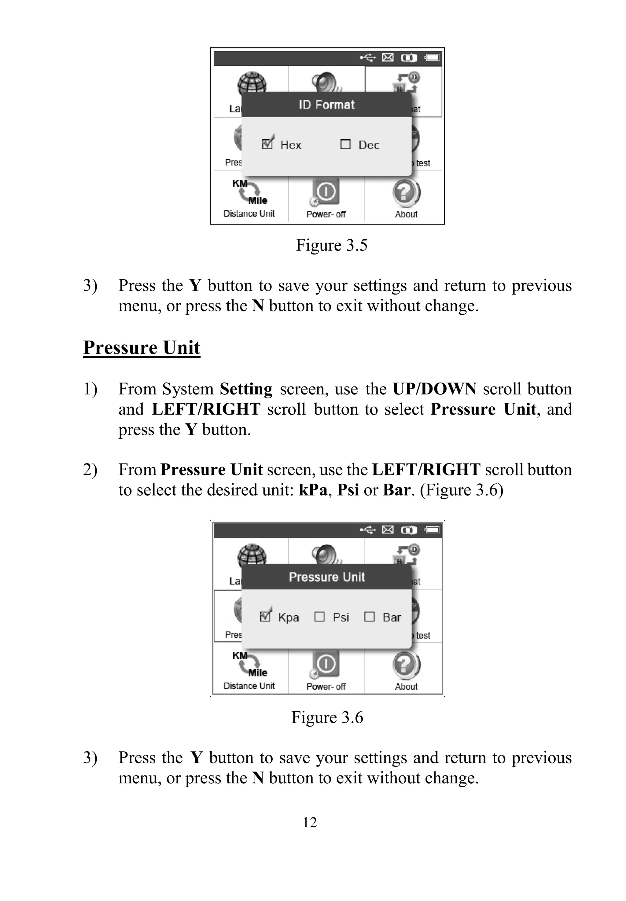
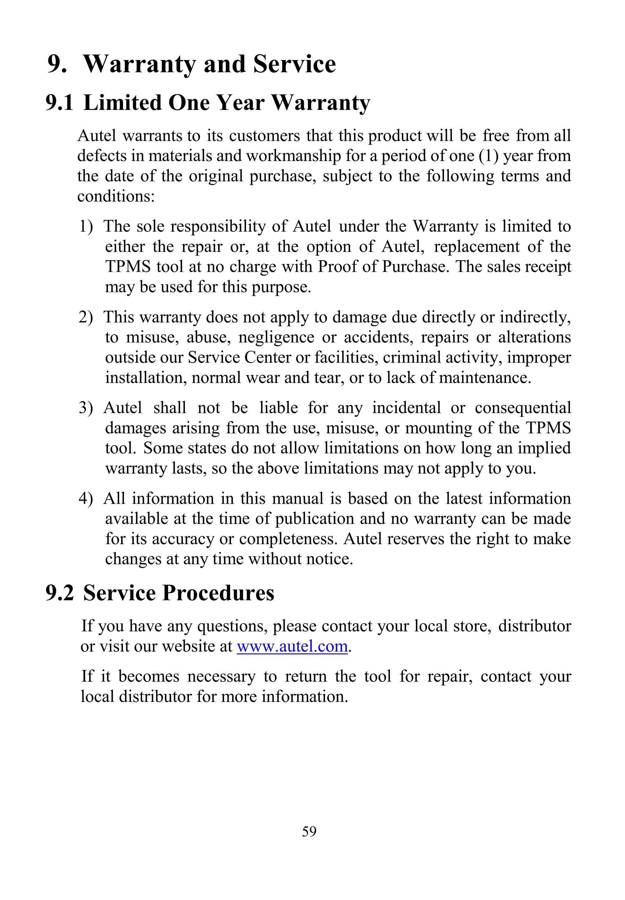
![54
Figure 7.2
2) Enter your Autel ID and password and wait for the Update
window to display. If you forget your password unintentionally,
you may always click the [Forget Password?] to link to our
website and get your password back.
3) In the Update window, select the items you want to install.
Usually, you should install all available updates.
Figure 7.3
Generally there are two ways to update the programs:
Batch Updating
1) Select the programs that you would update by clicking on the
check boxes next to those items. Then click the Update
Selected Items button on the right side of screen. Or](https://image.slidesharecdn.com/autelmaxitpmsts501professional-190114152900/75/Autel-TS501-User-Manual-56-2048.jpg)
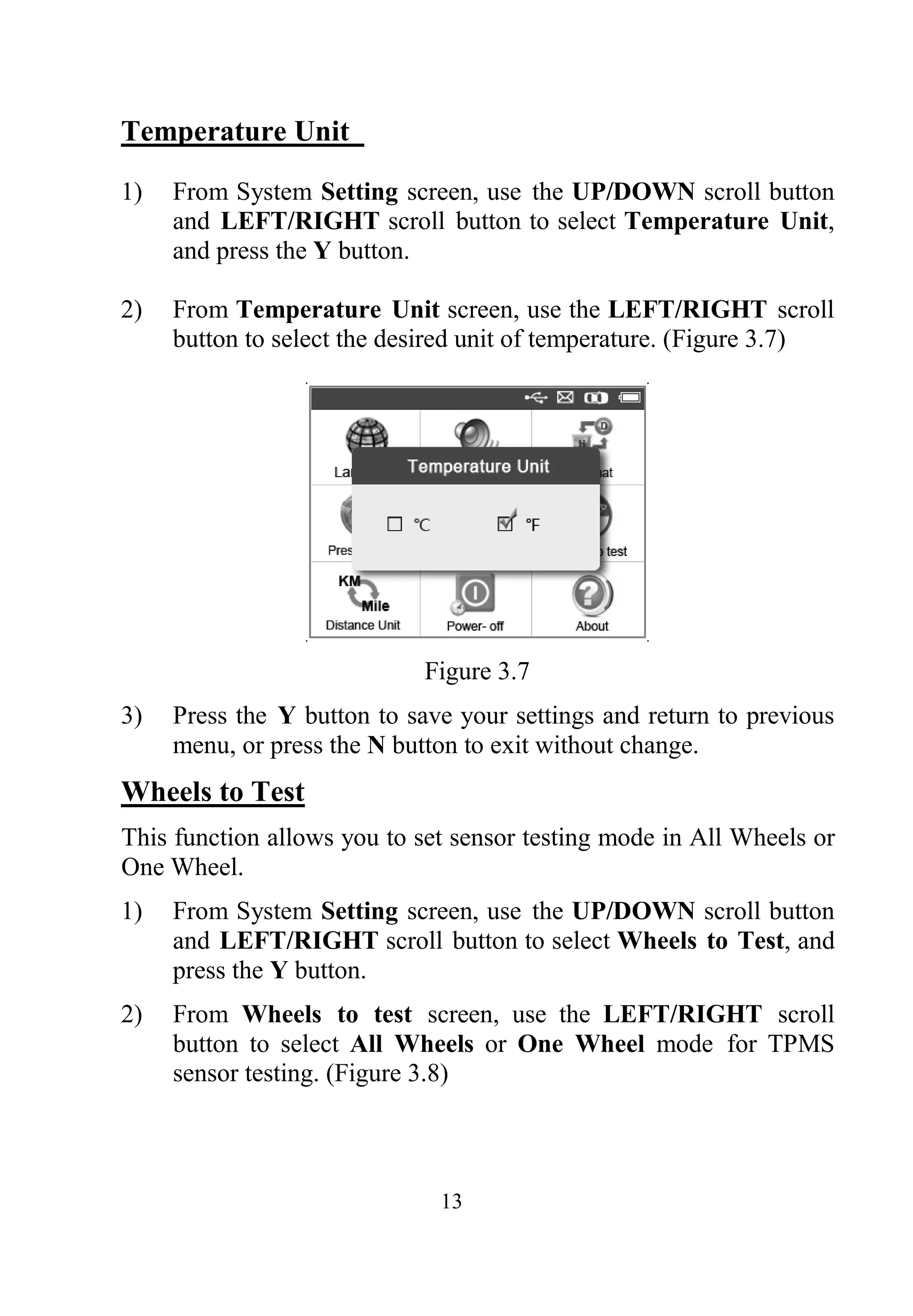
![55
2) Click on the Select All checkbox on the right side of screen and
all updatable items will be selected automatically. Then click
the Update Selected Items button on the right side of screen.
3) Check the updating process by observing the upper left progress
bar [Downloads] and upper right progress bar [Installs]. You
may also find progress information in the Status column of
updated items.
4) Anytime you could click the Pause button on the right side of
screen to suspend all progresses, and the state of those
suspended items would change to STOPPED.
5) To resume updating process, you may need to select those
suspended items again, and then click the Update Selected
Items button. The progress will resume from the break point.
6) When the downloading is completed, the downloaded programs
will be installed automatically. The new version will replace the
old version.
Single Updating
1) Find out the desired updating item and click the Install button
in the same line and the Install button changes to Pause at the
same time.
2) Check the updating process by observing the upper left progress
bar [Downloads] and upper right progress bar [Installs]. You
may also find progress information in the Status column of
updated items.
3) Anytime you could click the Pause button in the line to suspend
this progress, and the state of this item would change to
STOPPED.
4) To resume updating process, click the Install button in the line
again. The progress will resume from the break point.
5) When the downloading is completed, the downloaded program
will be installed automatically. The new version will replace the
old one.](https://image.slidesharecdn.com/autelmaxitpmsts501professional-190114152900/75/Autel-TS501-User-Manual-57-2048.jpg)


The document outlines essential information regarding the Tire Pressure Monitoring System (TPMS) and its related tools, including safety precautions, general information about TPMS legislation and operation, and specifications of the TPMS tool. It includes details about tool functionality, user interface features, system settings, battery charging, and troubleshooting procedures. The document serves as a comprehensive guide for users to operate TPMS effectively while adhering to safety protocols.


![Toyota Dashboard Warning Lights [FULL]](https://cdn.slidesharecdn.com/ss_thumbnails/toyota-warning-lights-211126044903-thumbnail.jpg?width=640&height=640&fit=bounds)


![Mini Cooper Dashboard Warning Lights: Symbols and Meanings [FULL LIST]](https://cdn.slidesharecdn.com/ss_thumbnails/mini-cooper-warning-lights-221021084944-27b65ebd-thumbnail.jpg?width=640&height=640&fit=bounds)


![Mazda Dashboard Warning Lights: Symbols and Meanings [FULL LIST]](https://cdn.slidesharecdn.com/ss_thumbnails/mazda-warning-lights-221021085358-dcf733ba-thumbnail.jpg?width=640&height=640&fit=bounds)


