Download to read offline


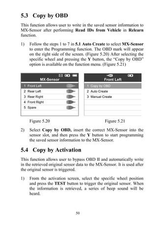
![2
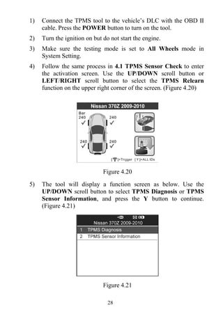
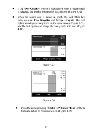
2. General Information
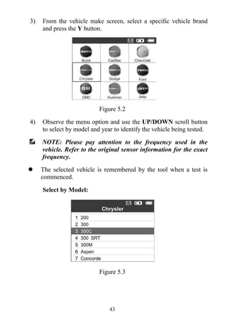
2.1 TPMS system review
A tire pressure monitoring system (TPMS) is an electronic system
designed to monitor the air pressure inside the pneumatic tires on
various types of vehicles. TPMS report real-time tire-pressure
information to the driver of the vehicle, either via a gauge, a
pictogram display, or a simple low-pressure warning light. TPMS
can be divided into two different types — direct (dTPMS) and
indirect (iTPMS). TPMS are provided both at an OEM (factory)
level as well as an aftermarket solution.
2.2 TPMS Legislation
In the United States, the United States Department of Transportation
(NHTSA) released the FMVSS No. 138, which requires an
installation of a Tire Pressure Monitoring System to all new
passenger cars, multipurpose passenger vehicles, trucks, and buses
that have a gross vehicle weight rating (GVWR) of 4,536 kg
(10,000 lbs.) or less, except those vehicles with dual wheels on an
axle, as of 2007. In the European Union, starting November 1, 2012,
all new models of passenger cars must be equipped with a TPMS,
with even tighter specifications that will be defined by the UNECE
Vehicle Regulations (Regulation No. 64). From November 1, 2014,
all new passenger cars sold in the European Union must be equipped
with TPMS. On July 13, 2010, the South Korean Ministry of Land,
Transport and Maritime Affairs announced a pending partial-revision
to the Korea Motor Vehicle Safety Standards (KMVSS), specifying
that "TPMS shall be installed to passenger vehicles and vehicles of
GVW 3.5 tons or less, ... [effective] on January 1, 2013 for new
models and on June 30, 2014 for existing models". Japan is expected
to adopt European Union legislation approximately one year after
European Union implementation. Further countries to make TPMS
mandatory include Russia, Indonesia, the Philippines, Israel,
Malaysia and Turkey.](https://image.slidesharecdn.com/autelts601maxitpms-190114154723/85/Autel-TS601-User-Manual-4-320.jpg)


![26
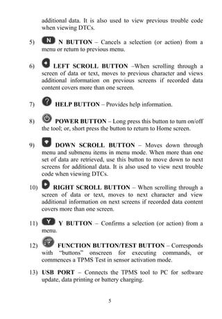
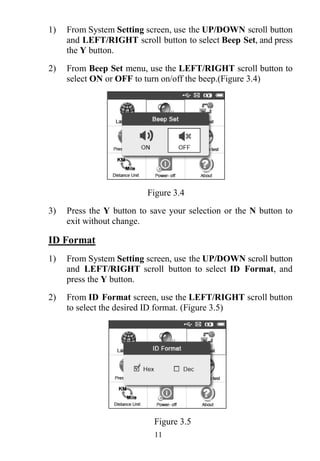
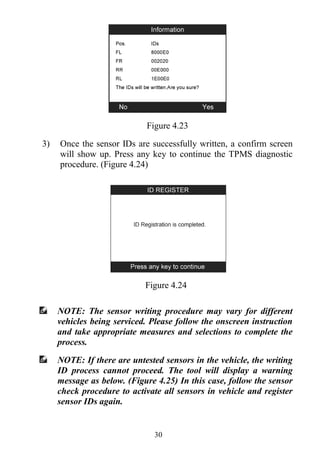
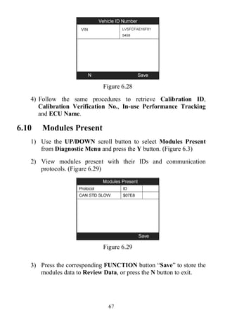
[Pos] – Indicates the wheel sensor position.
[ID-H/D] – Shows sensor ID data.
[KPa/Psi/Bar] – Indicates tire pressure.
[°C/°F] – Indicates tire temperature.
[BAT] – Indicates battery condition.
[Mode] – Defines tire sensor working mode or status.
[Modulation] – Indicates sensor signal amplitude.
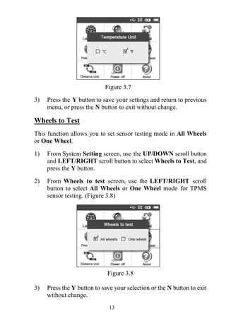
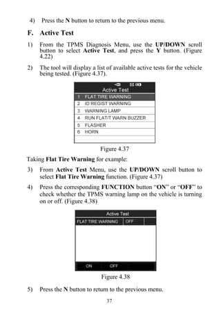
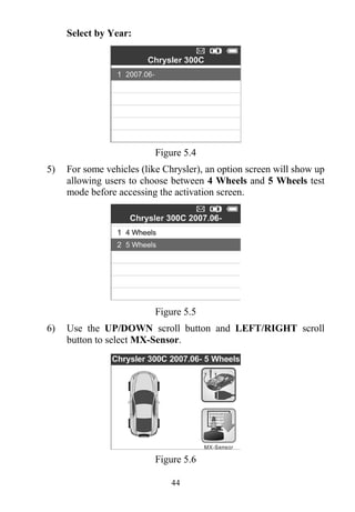
B. Select by Latest Test
This function allows you to review the last tested sensor data and
activate the sensor by using the wave signal of the latest trigger event,
which is very convenient and useful for technicians to wake up
sensors of the same vehicle.
1) Use the UP/DOWN scroll button and LEFT/RIGHT scroll
button to select Latest Test from Main Menu (Figure 3.1).
2) An activation screen with the previously activated sensor
information will show up (Figure 4.17). Use the UP/DOWN or
LEFT/RIGHT scroll button to select the desired wheel, and
press the TEST button to reactivate the sensor, or press the Y
button to view all detailed sensor data (Figure 4.18).
Figure 4.17](https://image.slidesharecdn.com/autelts601maxitpms-190114154723/85/Autel-TS601-User-Manual-28-320.jpg)


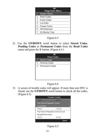
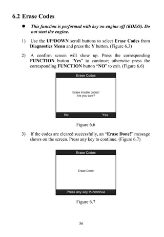
![53
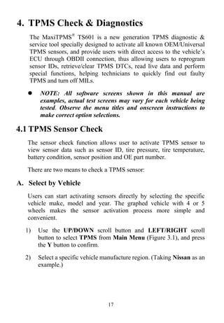
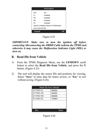
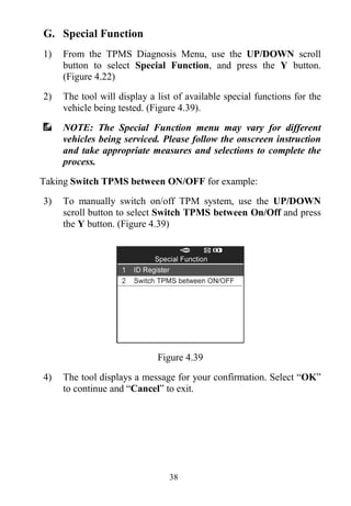
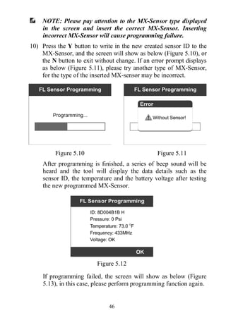
6. OBDII Diagnostics
The OBD II Diagnostics function is a fast-access option that allows
you to carry out a quick test on the engine system of OBD
II-compliant vehicles.
When more than one vehicle control module is detected by the scan
tool, you will be prompted to select the module where the data may
be retrieved. The most often to be selected are the Power-train
Control Module [PCM] and Transmission Control Module [TCM].
CAUTION: Don’t connect or disconnect any test equipment with
ignition on or engine running.
1) Turn the ignition off.
2) Locate the vehicle’s 16-pin Data Link Connector (DLC).
3) Plug the scan tool cable connector into the vehicle’s DLC.
4) Turn the ignition on. Engine can be off or running.
5) Turn on the scan tool. Select OBD II from the Main Screen.
(Figure 3.1)
6) Press the Y button to wait for the Menu to appear. A sequence
of messages displaying the OBD II protocols will be observed
on the display until the vehicle protocol is detected.
If the scan tool fails to communicate with the vehicle’s ECU
(Engine Control Unit) more than three times, a “LINKING
ERROR!” message shows up on the display.
Verify that the ignition is ON.
Check if the scan tool’s OBD II connector is securely
connected to the vehicle’s DLC.
Verify that the vehicle is OBD II compliant.
Turn the ignition off and wait for about 10 seconds. Turn the
ignition back to on and repeat the procedure from step 5.
If the “LINKING ERROR” message does not go away, then
there might be problems for the scan tool to communicate with](https://image.slidesharecdn.com/autelts601maxitpms-190114154723/85/Autel-TS601-User-Manual-55-320.jpg)


![75
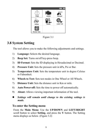
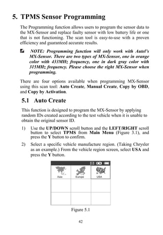
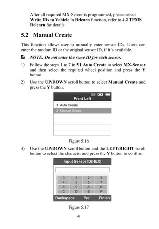
Figure 9.2
2) Enter your Autel ID and password and wait for the Update
window to display. If you forget your password unintentionally,
you may always click the [Forget Password?] to link to our
website and get your password back.
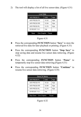
3) In the Update window, select the items you want to install.
Usually, you should install all available updates.
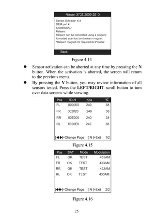
Figure 9.3
Generally there are two ways to update programs:
Batch Updating
1) Select the programs that you would update by clicking on the
check boxes next to those items. Then click the Update
Selected Items button on the right side of screen. Or](https://image.slidesharecdn.com/autelts601maxitpms-190114154723/85/Autel-TS601-User-Manual-77-320.jpg)
![76
2) Click on the Select All checkbox on the right side of screen and
all updatable items will be selected automatically. Then click
the Update Selected Items button on the right side of screen.
3) Check the updating process by observing the upper left progress
bar [Downloads] and upper right progress bar [Installs]. You
may also find progress information in the Status column of
updated items.
4) When the downloading is completed, the downloaded programs
will be installed automatically. The new version will replace the
old version.
5) Anytime you could click the Pause button on the right side of
screen to suspend all progresses.
6) To resume updating process, you may need to select those
suspended items again, and then click the Update Selected
Items button. The progress will resume from the break point.
Single Updating
1) Find out the desired updating item and click the Install button
in the same line, and the Install button changes to Pause at the
same time.
2) Check the updating process by observing the upper left progress
bar [Downloads] and upper right progress bar [Installs]. You
may also find progress information in the Status column of
updated items.
3) Anytime you could click the Pause button in the line to suspend
this progress.
4) To resume updating process, click the Install button in the line
again. The progress will resume from the break point.
5) When the downloading is completed, the downloaded program
will be installed automatically. The new version will replace the
old one.
6) Once the update is complete, disconnect the tool from the](https://image.slidesharecdn.com/autelts601maxitpms-190114154723/85/Autel-TS601-User-Manual-78-320.jpg)


The document provides comprehensive information on Tire Pressure Monitoring Systems (TPMS), including their benefits, legislation requirements, and operational details of a TPMS tool. It outlines safety precautions for using the tool, descriptions of its functionalities, specifications, and system settings. Additionally, the document contains diagnostic procedures and maintenance guidelines for effective utilization of TPMS technology.


![Mazda Dashboard Warning Lights: Symbols and Meanings [FULL LIST]](https://cdn.slidesharecdn.com/ss_thumbnails/mazda-warning-lights-221021085358-dcf733ba-thumbnail.jpg?width=640&height=640&fit=bounds)
![Mini Cooper Dashboard Warning Lights: Symbols and Meanings [FULL LIST]](https://cdn.slidesharecdn.com/ss_thumbnails/mini-cooper-warning-lights-221021084944-27b65ebd-thumbnail.jpg?width=640&height=640&fit=bounds)


![Toyota Dashboard Warning Lights [FULL]](https://cdn.slidesharecdn.com/ss_thumbnails/toyota-warning-lights-211126044903-thumbnail.jpg?width=640&height=640&fit=bounds)


![BMW Dashboard Warning Lights [FULL]](https://cdn.slidesharecdn.com/ss_thumbnails/bmwdashboardlights-211008082506-thumbnail.jpg?width=640&height=640&fit=bounds)


![[English Version]Maker-Ray Product Brochure V3 .pdf](https://cdn.slidesharecdn.com/ss_thumbnails/englishversionmaker-rayproductbrochurev3-260113094444-0156dbdc-thumbnail.jpg?width=640&height=640&fit=bounds)


