SlideShare a Scribd company logo
1 of 12
Download to read offline
US 20120286623A1
(19) United States
(12) Patent Application Publication (10) Pub. No.: US 2012/0286623 A1
(43) Pub. Date: Nov. 15, 2012Ogram
(54) ATMOSPHERIC ENERGY COLLECTION
(75) Inventor: Mark E. Ogram, Tucson, AZ (US)
(73) Assignee: Sefe, Inc., Tempe, AZ (US)
(21) Appl. No.: 13/103,963
(22) Filed: May 9, 2011
Publication Classi?cation
(51) Int. Cl.
H02N 3/00 (2006.01)
[H6(N
00 D
----/
500
(52) us. c1. ...................................................... .. 310/309
(57) ABSTRACT
The subject matter described herein is an atmospheric energy
collector. The atmospheric energy collector includes of a
Windsock arrangement that has a large up-Wind opening on
one side and that tapers from the larger up-Wind opening on
the one side to a small doWn-Wind opening on the other side.
The up-Wind side is secured to a tether such that an electri
cally conducting material (eg metal) included in construc
tion of the atmospheric energy collector is connected to the
tether. The Windsock arrangement is extended outWards by
Wind and the like atmospheric conditions such that the elec
trically conducting material collects the atmospheric energy
and transfers the collected energy to the tether.
502
504
Patent Application Publication Nov. 15, 2012 Sheet 1 0f 7 US 2012/0286623 A1
.02
w:
<H.wE
 I
Patent Application Publication Nov. 15, 2012 Sheet 2 0f 7 US 2012/0286623 A1
UH.QE
m.“.UE
Patent Application Publication Nov. 15, 2012 Sheet 3 0f 7 US 2012/0286623 A1
206
FIG.2
Patent Application Publication Nov. 15, 2012 Sheet 4 0f 7 US 2012/0286623 A1
Namwom
vom
Patent Application Publication Nov. 15, 2012 Sheet 5 0f 7 US 2012/0286623 A1
uw.QE
kg.VUQ
KNJUQNow
mw.wEQQQQQQN:HIll
WMEQQKWQQWRDSAQQQnwKmJ
mow
:
Nov
<6.DE
Patent Application Publication Nov. 15, 2012 Sheet 6 0f 7 US 2012/0286623 A1
Patent Application Publication Nov. 15, 2012 Sheet 7 0f 7 US 2012/0286623 A1
@.wE
EmEmsumEmczmiumwEm:>n_V6862;*0Emmw;$3.54
wow
mmmc?3556585553,Emtzu2
wow
BUEbwE2653053“3:83
“ES,m5>n_Ema/So8:82pmV6865;
wow
wow
US 2012/0286623 A1
ATMOSPHERIC ENERGY COLLECTION
TECHNICAL FIELD
[0001] The subject matter described herein relates to a
light-Weight, extendible electricity collecting Windsock
arrangement comprising an enhanced collection surface for
atmospheric electrical energy collection.
BACKGROUND
[0002] The atmosphere above the earth is knoWn to include
electrical charge. The earth’s surface is negatively charged,
While the air above it is positively charged. All atmospheric
effects are a result of an interplay betWeen these tWo huge
areas of opposite electrical energy. The potential difference
betWeen the positively charged atmosphere and the nega
tively charged earth surface causes atmospheric electrical
energy to be developed. Some of this atmospheric electrical
energy may be experienced through thunderstorms.
[0003] Even though there is a huge amount ofatmospheric
electrical energy in the atmosphere, collection of the atmo
spheric electrical energy still remains a problem. Due to high
voltage and loW current conditions, there is a need for large
collection surfaces for maximizing the collection of atmo
spheric electrical energy. Note that the terms atmospheric
electricity, atmospheric energy, and atmospheric electrical
energy have been used interchangeably in this speci?cation.
[0004] The problem of loW current is compounded by a
heavy Weight of the collectors of atmospheric electrical
energy. The heavy Weight ofthe collectors increases payload
requirements of a lift mechanism, Which may be used to lift
the collectors to an appropriate height or altitude so that the
collection of atmospheric electrical energy is maximized.
Thus, a need exists for large yet light-Weight collectors such
that payload requirements for the lift mechanism remain rea
sonable.
SUMMARY
[0005] The subject matter described herein relates to an
atmospheric energy collector. The atmospheric energy col
lector includes an electricity collecting Windsock arrange
ment that has a large up-Wind opening on one side and that
tapers from the larger up-Wind opening on the one side to a
small doWn-Wind opening on the other side. The up-Wind side
is secured to a tether such that an electrically conducting
material (eg metal) included in construction of the atmo
spheric energy collector is connected to the tether. The elec
tricity collecting Windsock arrangement is extended outWards
by Wind and the like atmospheric conditions such that the
electrically conducting material collects the atmospheric
energy and transfers the collected energy to the tether. Fur
ther, the electricity collecting Windsock includes light-Weight
collectors such that payload requirements for the lift mecha
nism remain reasonable (i.e. remain Within a predetermined
value).
[0006] In one aspect, an electricity collection apparatus
includes a tether and a Windsock. The Windsock is formed of
an insulation material With a metal deposited on at least a
portion ofthe insulation material. The metal ofthe Windsock
is electrically connected to the tether. The Windsock extends
in a direction ofambient Wind to provide a surface area based
on the ambient Wind, and the surface area provides the metal
to collect electrical energy from the ambient Wind, the col
lected electrical energy being transferred to the tether.
Nov. 15, 2012
[0007] In another aspect, an electricity collection apparatus
includes a Windsock formed of an insulation material the
Windsock to extend in a direction ofambient Wind to provide
a surface area based on the ambient Wind. The apparatus
further includes one or more electrical conductors provided
on at least a portion of the insulation material to collect
electrical energy from the ambient Wind. The apparatus fur
ther includes an electrically conductive tether connected With
Windsock to anchor the Windsock in the direction of the
ambient Wind, the electrically conductive tether being elec
trically connected to the one or more electrical conductors
provided on at least a portion of the insulation material to
transfer the collected electrical energy from the one or more
electrical conductors to an electrical storage.
[0008] The subject matter described herein provides many
advantages. For example, large collection surfaces alloW a
maximiZed collection of atmospheric energy. Moreover, the
light-Weight collectors alloW payloadrequirements forthe lift
mechanism to remain reasonable (i.e. remain Within a prede
termined value).
[0009] The details of one or more variations ofthe subject
matter described herein are set forth in the accompanying
draWings and the description beloW. Other features and
advantages of the subject matter described herein Will be
apparent from the description and draWings, and from the
claims.
DESCRIPTION OF DRAWINGS
[0010] The accompanying drawings, Which are incorpo
rated in and constitute a part ofthis speci?cation, shoW certain
aspects of the subject matter disclosed herein and, together
With the description, help explain some of the principles
associated With the disclosed implementations. In the draW
1ngs,
[0011] FIG. 1A illustrates extendible electricity collecting
Windsock arrangement that is used for collection of atmo
spheric electrical energy in accordance With implementations
ofthe current subject matter;
[0012] FIG. 1B illustrates a cross-section ofone implemen
tation ofthe electrically conducting Windsock in accordance
With implementations ofthe current subject matter;
[0013] FIG. 1C illustrates a cross-section ofanother imple
mentation of the electricity collecting Windsock in accor
dance With implementations of the current subject matter;
[0014] FIG. 2 illustrates an exemplary conductive line in
accordance With implementations ofthe current subject mat
ter;
[0015] FIG. 3A illustrates a front vieW of a conductive line
in accordance With implementations of the current subject
matter;
[0016] FIG. 3B illustrates a top vieW ofthe conductive line
shoWn in FIG. 3 in accordance With implementations of the
current subject matter;
[0017] FIGS. 4A, 4B, and 4C illustrate electrical schemat
ics for handling the static charge from the atmosphere in
accordance With implementations ofthe current subject mat
ter;
[0018] FIG. 5 illustrates an adjusting apparatus (Winch
motor and spool) that enables adjustment of location/height
of the electricity collecting Windsock arrangement in accor
dance With implementations ofthe current subject matter; and
[0019] FIG. 6 is a process How diagram illustrating aspects
of a method in accordance With implementations of the cur
rent subject matter.
US 2012/0286623 A1
[0020] When practical, similar reference numbers denote
similar structures, features, or elements.
DETAILED DESCRIPTION
[0021] To address these and potentially other issues With
currently available solutions, one or more implementations of
the current subject matter provide methods, systems, articles
or manufacture, and the like that can, among other possible
advantages, provide an energy collector formed as a Wind
sock and having an enhanced collection surface for atmo
spheric electrical energy collection. In preferred implemen
tations, an electricity collecting Windsock is formed as a
?exible cylinder, a truncated cone, or a cone With a metal
surface, and is mounted to a mast or other tether so as to
capture ambient Wind Which extends the Windsock outWard
from the mast, in turn forming the largest possible surface
area for the Wind conditions to enable the metal surface to
collect atmospheric amperage. The collected amperage is
transferred from the metal surface ofthe electricity collecting
Windsock to the mast ortether, and eventually to an electricity
storage device. Although implementations in Which Wind
sock arrangements having one Windsock each are discussed
beloW, those or ordinary skill in the art understand that a
Windsock arrangement may include tWo or more Windsocks
for enhanced atmospheric electricity collection.
[0022] FIG. 1A illustrates an implementation of electricity
collecting Windsock arrangement 100 that is used to collect
atmospheric electrical energy. The electricity collecting
Windsock arrangement 100 includes an extendible electricity
collecting Windsock 102. The extendible electricity collect
ing Windsock 102 is made ofa material that has a high tensile
strength and provides electrical insulation. This electrically
insulating material 134 (discussed beloW With respect to FIG.
1B) may be a plastic or a ?exible glass, such as polyester like
polyethylene terephthalate (PET) or biaxially-oriented poly
ethylene terephthalate (BoPET). BoPET is knoWn in the
industry by different trade names, some of Which are Mylar,
Melinex and Hostaphan.
[0023] As is described later With respect to FIGS. 1B and
1C, Which illustrate cross-sections of implementations of
electricity collecting Windsock 102, a thin coat of an electri
cally conducting material 132, 162 is deposited on the elec
trically insulating material 134. The deposited electrically
conducting material 132, 162 is a good conductor ofelectric
ity, andhelps electricity collecting Windsock 102 to tap atmo
spheric electrical energy. The electrically conducting mate
rial may be any one of a metal or a suitable alloy, such as one
of or a combination of one or more of gold, silver, copper,
aluminum, and the like.
[0024] The electricity collecting Windsock 102 has a large
up-Wind opening up-Wind opening 104 on one side. The
electricity collecting Windsock 102 tapers from the large up
Wind opening 104 on the one side to a small doWn-Wind
opening 106 on the other side of the electricity collecting
Windsock 102. The up-Wind opening 104 has a metal loop 110
on the circumference ofthe up-Wind opening 104. The metal
loop 110 is attached to a tether 112 using an attachment
mechanism 114. The attachment mechanism 114 may include
a soldering mechanism. In some implementations, other
attachment mechanisms 114 are also knoWn to be used, such
as nut and bolt mechanism, threading mechanism, gluing
mechanism, and the like. The electricity collecting Windsock
102 is extended outWards by Wind 116 and/or like atmo
spheric conditions suchthat the electrically conducting mate
Nov. 15, 2012
rial (e.g. metal) collects the atmospheric electrical energy and
transfers the collected energy to the tether 112.
[0025] The tether 112 includes a conductive line that is
isolated from the ground. The conductive line is used to
transfer the collected atmospheric electrical energy from the
electricity collecting Windsock 102 to an electricity storage
device (not shoWn) Where the collected atmospheric charge
may be gathered for later or simultaneous use.
[0026] When Wind 116 strikes against the electricity col
lecting Windsockarrangement 100 inthe direction illustrated,
the electricity collecting Windsock 102 extends outWard, thus
alloWing the electrically conducting material 132 (discussed
beloW With respect to FIG. 1B) to collect maximum possible
atmospheric electricity. In one implementation, the outWard
extension 118 is ?fty feet or more. When there is no Wind, the
electricity collecting Windsock 102 may be in a relatively
compressed state such that the length of the electricity col
lecting Windsock 102 is less than the outWard extension 118
caused by Windy conditions or like atmospheric conditions.
The collected atmospheric electrical energy is communicated
to the tether 112.
[0027] FIG. 1B illustrates a cross-section 130 ofone imple
mentation of the electrically conducting Windsock 102. The
cross-section 130 illustrates the electrically conducting mate
rial 132 deposited on the inner surface of the electrically
insulating material 134. The electricity collecting Windsock
102 includes the electrically conducting material 132 and the
electrically insulating material 134 such that the electrically
conducting material 132 forms the inner surface of the elec
tricity collecting Windsock 102. When the Wind 116 strikes
the electricity collecting Windsock arrangement, the electric
ity collecting Windsock 102 extends outWard, thus alloWing
the electrically conducting material 132 to collect maximum
possible atmospheric electricity. The electrically conducting
material 132 may include multiple collectors that are spaced
apart such that the collection surface is greatly enhanced. The
multiple collectors may be spaced apart in patterns, such as
spaced apart lines, squares, rectangles, circles, andthe like, or
any other pattern that may maximiZe the collection of the
atmospheric electrical energy. As noted above, the electri
cally insulating material 134 may be a plastic or a ?exible
glass, such as polyester like polyethylene terephthalate (PET)
or biaxially-oriented polyethylene terephthalate (BoPET).
The electrically conducting material 132 may be a metal or
alloy, such as one ofor a combination of one or more of gold,
silver, copper, aluminum, and the like.
[0028] FIG. 1C illustrates a cross-section 160 of another
implementation of the electricity collecting Windsock 102.
The electrically conducting material (eg metal deposit) 132,
162 may be placed on both sides ofthe electrically insulating
material 134 such that the collection ability is increased even
further. Multiple collectors are implemented and are spaced
apart on electrically conducting material 132, 162 such that
the collection surface is greatly enhanced. The multiple col
lectors may form one or more patterns, as noted above With
respect to FIG. 1B. Furthermore, the electrically insulating
material 134 (eg mylar) used in the electricity collecting
Windsock 102 is light, thereby minimiZing the overall Weight
of the electricity collecting Windsock 102 and reducing the
Weight for payload calculations. The electrically conducting
materials 132, 162 may be an electrically conducting metal or
alloy, such as one of or a combination of at least one of gold,
copper, aluminum, silver, and the like. The electrically con
US 2012/0286623 A1
ducting materials 132, 162 may be made of the same metal/
alloy or a different metal/alloy.
[0029] The electrically conducting materials 132, 162 may
be attached to the electrically insulating material 134 by a
gluing mechanism. In some implementations, other attach
ment mechanisms are known to be implemented, such as
paint coating mechanism, a threading mechanism, a nut and
bolt mechanism, soldering mechanism, and the like. The
attachment mechanism betWeen the electrically conducting
material 132 and the electrically insulating material 134 may
or may not be the same as the attachment mechanism betWeen
the electrically conducting material 162 and the electrically
insulating material 134.
[0030] FIG. 2 illustrates an exemplary conductive line in
accordance With one implementation. This type ofconductive
line is commonly referred to as poly-Wire. The conductive
line consists ofmultiple interWoven strands ofplastic 202 and
204 Woven into a cord or rope arrangement having inter
tWined therein exposed metal Wires 206 and 208. Although
FIG. 2 illustrates tWo plastic strands and tWo metal Wires, any
number ofpossible combinations ofplastic strands and metal
Wires is possible. The exposedmetal Wires 206 and 208 attract
the atmospheric static charge and transmit the charge doWnto
the electricity storage device (not shoWn).
[0031] FIG. 3A illustrates a front vieW of a conductive line
300 in accordance With another implementation. FIG. 3B
illustrates a top vieW ofthe conductive line 300 illustrated in
FIG. 3. The conductive line 300 creates an ioniZed pathWay
for the How of the static charges from the atmosphere to the
electricity storage device via the electricity collecting Wind
sock arrangement 100. This conductive line utiliZes a tube
302 having an outer layer 304 of PET Film (Biaxially-ori
ented polyethylene terephtalate polyester ?lm). The tube 302
provides exceptionallyhightensile strengthandis chemically
and dimensionally stable. In one implementation, the tube
302 may have an ideal diameter of betWeen tWo and three
inches. An interior metal coating 306 provides an initial con
duit forthe How ofstatic charge. The static charge through the
metal may force the tube 302 to expand due to the repulsion
experienced by like charges. Further, the How of electricity
causes the interior of the tube 302 to become ioniZed to
provide an additional pathWay for the atmospheric static
charges to the electricity storage device (not shoWn).
[0032] FIGS. 4A, 4B, and 4C illustrate electrical schemat
ics for handling the static charge from the atmosphere. By
maintaining the voltage being collected in a prescribedrange,
an electrical conversion system is easily designed. While
FIGS. 4A, 4B, and 4C illustrate some electrical con?gura
tions, those of ordinary skill in the art readily recogniZe a
variety ofother con?gurations that may serve the same func
tion.
[0033] Referencing FIG. 4A, Direct Current In (DC IN)
402 is buffered by a gang of capacitors 404 before being
communicated to a DC/AC converter 406. The DC/AC con
verter converts the direct current into alternating current suit
able for placement over an existing electrical grid 408 such as
normally found from a poWer-plant. Those ofordinary skill in
the art readily recogniZe a variety of DC/AC converters that
may Work in this capacity.
[0034] FIG. 4B illustrates an electrical arrangement suit
able for use in charging a battery. DC IN 402 is buffered by
capacitor bank 404 before entering into a step doWn trans
former 408. Step doWn transformer 408 reduces the voltage
so that the voltage can safely be introduced into battery 410,
Nov. 15, 2012
Which is connected to ground 412 at the battery’s other pole.
Those ofordinary skill in the art readily recogniZe a variety of
batteries that may Work in this capacity.
[0035] In FIG. 4C, DC IN 402 is fed into an adjustable
rheostat 414, Which is controlled by the controller so that the
DC OUT 416 falls Within a speci?ed range.
[0036] FIG. 5 illustrates an adjusting apparatus 500 that
enables adjustment of height of the electricity collecting
Windsock arrangement 100 in accordance With one imple
mentation. As per one implementation, the height ofthe elec
tricity collecting Windsock 102 can be adjusted using a Winch
motor 502 and a spool 504. The Winch motor 502 and the
spool 504 can release or WithdraW the tether 112 to adjust the
height of the electricity collecting Windsock 102 that is con
nected to the tether 112. In one implementation, this release
and the WithdraWal may be performed manually. In another
implementation, this release and the WithdraWal may be per
formed automatically based on information obtained from a
sensor system that measures atmospheric electrical energy
being collected per unit time. If the sensor indicates that a
current How is diminishing, then the tether 112 is released/
extended from the spool 504 to increase the altitude of the
electricity collecting Windsock 102 such that more static
charge from the atmosphere is gathered. If the sensor indi
cates that collected atmospheric electrical energy exceeds a
preset level per unit time, the tether 112 is WithdraWn onto the
spool 504 to decrease the static charge being collected from
the atmosphere.
[0037] FIG. 6 is a process How diagram illustrating aspects
of a method consistent With implementations of the current
subject matter. At step 602, the functioning ofthe electricity
collecting Windsock arrangement 100 depends on Whether
atmospheric conditions are Windy. If the atmospheric condi
tions are Windy, the Wind 116 stretches/extends outWard the
electricity collecting Windsock 102iStep 604. Next, it is
determinedWhether the atmospheric electrical energy (atmo
spheric current) that is collected is in a predetermined
rangeiStep 606. If the collected atmospheric electrical
energy is in the predetermined range, the How goes back to
step 604. Ifthe current is not in the predetermined range, the
height of the electricity collecting Windsock 102 may be
adjusted using adjusting apparatus 500, such as the Winch
motor 502 and spool 504. One skilled in the art understands
that other implementations may include any other adjusting
apparatus 500, such as a pulley, a Wheel mechanism, or the
like.
[0038] The implementations set forth in the foregoing
description do not represent all implementations consistent
With the subject matter described herein. Instead, they are
merely some examples consistent With aspects related to the
described subject matter. Although a feW variations have been
described in detail herein, other modi?cations or additions are
possible. In particular, further features and/or variations can
be provided in addition to those set forth herein. For example,
the implementations described above can be directed to vari
ous combinations and sub-combinations ofthe disclosed fea
tures and/or combinations and sub-combinations of one or
more features further to those disclosed herein. In addition,
the logic ?oWs depicted in the accompanying ?gures and/or
described herein do not necessarily require the particular
order shoWn, or sequential order, to achieve desirable results.
The scope of the folloWing claims may include other imple
mentations or embodiments.
US 2012/0286623 A1
What is claimed is:
1. An electricity collection apparatus comprising:
a tether; and
a Windsock formed of an insulation material With a metal
deposited on at least a portion ofthe insulation material,
the metal of the Windsock being electrically connected
to the tether, the Windsock to extend in a direction of
ambient Wind to provide a surface area based on the
ambient Wind, the surface area providing the metal to
collect electrical energy from the ambient Wind, the
collected electrical energy being transferred to the
tether.
2. The apparatus in accordance With claim 1, Wherein the
metal is deposited on at least one of opposite sides of the
insulation material.
3. The apparatus in accordance With claim 2, Wherein the
metal is a metal selected from a group of metals comprising
gold, silver, copper and aluminum.
4. The apparatus in accordance With claim 1, Wherein the
insulation material is a polyester ?lm.
5. The apparatus in accordance With claim 1, Wherein the
transferred electrical energy at the tether is furthertransferred
from the tether to an electricity storage device.
6. The apparatus in accordance With claim 1, Wherein the
metal comprises conductors that are light-Weight thereby
alloWing payload requirements for adjusting the Windsock to
an optimum location to be Within a predetermined value, the
optimum location comprising a height of the Windsock from
ground level.
7. The apparatus in accordance With claim 6, Wherein the
deposited metal conductors form a pattern that maximizes the
collection of the electrical energy at the optimum location.
8. An electricity collection apparatus comprising:
a Windsock formed ofan insulationmaterial having a metal
deposited on at least a portion ofthe insulation material,
the Windsock to extend in a direction ofambient Wind to
provide a surface area based on the ambient Wind, the
surface area providing the metal to collect electrical
energy from the ambient Wind; and
an electrically conductive tether connected With Windsock
to anchor the Windsock in the direction of the ambient
Nov. 15, 2012
Wind, the electrically conductive tether being electri
cally connected to the metal of the insulation material,
the collected electrical energy being transferred to the
tether.
9. The apparatus in accordance With claim 8, Wherein the
metal is deposited on at least one of opposite sides of the
insulation material.
10. The apparatus in accordance With claim 9, Wherein the
metal is a metal selected from a group of metals comprising
gold, silver, copper and aluminum.
11. The apparatus in accordance With claim 8, Wherein the
insulation material is a polyester ?lm.
12. The apparatus in accordance With claim 8, Wherein the
transferred electrical energy at the tether is further transferred
from the tether to an electricity storage device.
13. The apparatus in accordance With claim 8, Wherein the
metal comprises conductors that are light-Weight thereby
alloWing payload requirements for adjusting the Windsock to
an optimum location to be Within a predetermined value, the
optimum location comprising a height of the Windsock from
ground level.
14. The apparatus in accordance With claim 13, Whereinthe
metal conductors form a patternthat maximiZes the collection
ofthe electrical energy at the optimum location.
15. An electricity collection apparatus comprising:
a Windsock formed of an insulation material the Windsock
to extend in a direction of ambient Wind to provide a
surface area based on the ambient Wind;
one or more electrical conductors provided on at least a
portion of the insulation material to collect electrical
energy from the ambient Wind; and
an electrically conductive tether connected With Windsock
to anchor the Windsock in the direction of the ambient
Wind, the electrically conductive tether being electri
cally connected to the one or more electrical conductors
provided on at least a portion ofthe insulation material to
transfer the collected electrical energy from the one or
more electrical conductors to an electrical storage.
* * * * *

More Related Content

What's hot

Hybrid renewable energy photovoltaic and darrieus VAWT as propulsion fuel of ...
Hybrid renewable energy photovoltaic and darrieus VAWT as propulsion fuel of ...Hybrid renewable energy photovoltaic and darrieus VAWT as propulsion fuel of ...
Hybrid renewable energy photovoltaic and darrieus VAWT as propulsion fuel of ...journalBEEI
 
Sizing Optimization of Stand-Alone Wind Power System Using Hybrid Energy Stor...
Sizing Optimization of Stand-Alone Wind Power System Using Hybrid Energy Stor...Sizing Optimization of Stand-Alone Wind Power System Using Hybrid Energy Stor...
Sizing Optimization of Stand-Alone Wind Power System Using Hybrid Energy Stor...ijsrd.com
 
Wave-to-Wire Model of an Ocean Wave Energy Converter
Wave-to-Wire Model of an Ocean Wave Energy ConverterWave-to-Wire Model of an Ocean Wave Energy Converter
Wave-to-Wire Model of an Ocean Wave Energy ConverterJakir Hossain
 
Electricity from wind energy
Electricity from wind energyElectricity from wind energy
Electricity from wind energyH Janardan Prabhu
 
Evaluation of the Energy Performance of the Amougdoul Wind Farm, Morocco
Evaluation of the Energy Performance of the Amougdoul Wind Farm, Morocco Evaluation of the Energy Performance of the Amougdoul Wind Farm, Morocco
Evaluation of the Energy Performance of the Amougdoul Wind Farm, Morocco IJECEIAES
 
The modeling and dynamic characteristics of a variable speed wind turbine
The modeling and dynamic characteristics of a variable speed wind turbineThe modeling and dynamic characteristics of a variable speed wind turbine
The modeling and dynamic characteristics of a variable speed wind turbineAlexander Decker
 
11.the modeling and dynamic characteristics of a variable speed wind turbine
11.the modeling and dynamic characteristics of a variable speed wind turbine11.the modeling and dynamic characteristics of a variable speed wind turbine
11.the modeling and dynamic characteristics of a variable speed wind turbineAlexander Decker
 
Domestic Solar - Aero - Hydro Power Generation System
Domestic Solar - Aero - Hydro Power Generation SystemDomestic Solar - Aero - Hydro Power Generation System
Domestic Solar - Aero - Hydro Power Generation SystemIOSR Journals
 
Renewable Energy Storage
Renewable Energy StorageRenewable Energy Storage
Renewable Energy Storageijtsrd
 
International Journal of Engineering Research and Development
International Journal of Engineering Research and DevelopmentInternational Journal of Engineering Research and Development
International Journal of Engineering Research and DevelopmentIJERD Editor
 
Airfoil linear wind generator (alwg) as a novel wind energy extraction approach
Airfoil linear wind generator (alwg) as a novel wind energy extraction approachAirfoil linear wind generator (alwg) as a novel wind energy extraction approach
Airfoil linear wind generator (alwg) as a novel wind energy extraction approachijmech
 
Improved backtracking search optimization algorithm for PV/Wind/FC system
Improved backtracking search optimization algorithm for PV/Wind/FC systemImproved backtracking search optimization algorithm for PV/Wind/FC system
Improved backtracking search optimization algorithm for PV/Wind/FC systemTELKOMNIKA JOURNAL
 
Feasibility Study of a Grid Connected Hybrid Wind/PV System
Feasibility Study of a Grid Connected Hybrid Wind/PV SystemFeasibility Study of a Grid Connected Hybrid Wind/PV System
Feasibility Study of a Grid Connected Hybrid Wind/PV SystemIJAPEJOURNAL
 

What's hot (20)

Hybrid renewable energy photovoltaic and darrieus VAWT as propulsion fuel of ...
Hybrid renewable energy photovoltaic and darrieus VAWT as propulsion fuel of ...Hybrid renewable energy photovoltaic and darrieus VAWT as propulsion fuel of ...
Hybrid renewable energy photovoltaic and darrieus VAWT as propulsion fuel of ...
 
B44080512
B44080512B44080512
B44080512
 
Sizing Optimization of Stand-Alone Wind Power System Using Hybrid Energy Stor...
Sizing Optimization of Stand-Alone Wind Power System Using Hybrid Energy Stor...Sizing Optimization of Stand-Alone Wind Power System Using Hybrid Energy Stor...
Sizing Optimization of Stand-Alone Wind Power System Using Hybrid Energy Stor...
 
Wave-to-Wire Model of an Ocean Wave Energy Converter
Wave-to-Wire Model of an Ocean Wave Energy ConverterWave-to-Wire Model of an Ocean Wave Energy Converter
Wave-to-Wire Model of an Ocean Wave Energy Converter
 
Electricity from wind energy
Electricity from wind energyElectricity from wind energy
Electricity from wind energy
 
Evaluation of the Energy Performance of the Amougdoul Wind Farm, Morocco
Evaluation of the Energy Performance of the Amougdoul Wind Farm, Morocco Evaluation of the Energy Performance of the Amougdoul Wind Farm, Morocco
Evaluation of the Energy Performance of the Amougdoul Wind Farm, Morocco
 
N1304029496
N1304029496N1304029496
N1304029496
 
The modeling and dynamic characteristics of a variable speed wind turbine
The modeling and dynamic characteristics of a variable speed wind turbineThe modeling and dynamic characteristics of a variable speed wind turbine
The modeling and dynamic characteristics of a variable speed wind turbine
 
11.the modeling and dynamic characteristics of a variable speed wind turbine
11.the modeling and dynamic characteristics of a variable speed wind turbine11.the modeling and dynamic characteristics of a variable speed wind turbine
11.the modeling and dynamic characteristics of a variable speed wind turbine
 
Domestic Solar - Aero - Hydro Power Generation System
Domestic Solar - Aero - Hydro Power Generation SystemDomestic Solar - Aero - Hydro Power Generation System
Domestic Solar - Aero - Hydro Power Generation System
 
Renewable Energy Storage
Renewable Energy StorageRenewable Energy Storage
Renewable Energy Storage
 
Q13020298106
Q13020298106Q13020298106
Q13020298106
 
International Journal of Engineering Research and Development
International Journal of Engineering Research and DevelopmentInternational Journal of Engineering Research and Development
International Journal of Engineering Research and Development
 
P1302029097
P1302029097P1302029097
P1302029097
 
Airfoil linear wind generator (alwg) as a novel wind energy extraction approach
Airfoil linear wind generator (alwg) as a novel wind energy extraction approachAirfoil linear wind generator (alwg) as a novel wind energy extraction approach
Airfoil linear wind generator (alwg) as a novel wind energy extraction approach
 
20120140503014 2
20120140503014 220120140503014 2
20120140503014 2
 
278 icaer 2013 revised
278 icaer 2013 revised278 icaer 2013 revised
278 icaer 2013 revised
 
Paper Final
Paper FinalPaper Final
Paper Final
 
Improved backtracking search optimization algorithm for PV/Wind/FC system
Improved backtracking search optimization algorithm for PV/Wind/FC systemImproved backtracking search optimization algorithm for PV/Wind/FC system
Improved backtracking search optimization algorithm for PV/Wind/FC system
 
Feasibility Study of a Grid Connected Hybrid Wind/PV System
Feasibility Study of a Grid Connected Hybrid Wind/PV SystemFeasibility Study of a Grid Connected Hybrid Wind/PV System
Feasibility Study of a Grid Connected Hybrid Wind/PV System
 

Similar to Atmospheric Energy Collector Windsock

Staticcleccollection
StaticcleccollectionStaticcleccollection
Staticcleccollectiontavennerpride
 
Atmospheric & RF Electricity Collectors
Atmospheric & RF Electricity CollectorsAtmospheric & RF Electricity Collectors
Atmospheric & RF Electricity Collectorsuniqueprophai
 
A Novel Approach Concerning Wind Power Enhancement
A Novel Approach Concerning Wind Power EnhancementA Novel Approach Concerning Wind Power Enhancement
A Novel Approach Concerning Wind Power EnhancementWaqas Tariq
 
Analysis characteristics of power PV cells and wind turbine from power genera...
Analysis characteristics of power PV cells and wind turbine from power genera...Analysis characteristics of power PV cells and wind turbine from power genera...
Analysis characteristics of power PV cells and wind turbine from power genera...IOSR Journals
 
US Patent - Rotating electrostatic propulsion system
US Patent - Rotating electrostatic propulsion systemUS Patent - Rotating electrostatic propulsion system
US Patent - Rotating electrostatic propulsion systemExopolitics Hungary
 
Effect analysis of the different channel length and depth of photovoltaic the...
Effect analysis of the different channel length and depth of photovoltaic the...Effect analysis of the different channel length and depth of photovoltaic the...
Effect analysis of the different channel length and depth of photovoltaic the...IJECEIAES
 
Modeling of Wind Energy on Isolated Area
Modeling of Wind Energy on Isolated AreaModeling of Wind Energy on Isolated Area
Modeling of Wind Energy on Isolated AreaIJPEDS-IAES
 
Impact of solar radiation and temperature levels on the variation of the seri...
Impact of solar radiation and temperature levels on the variation of the seri...Impact of solar radiation and temperature levels on the variation of the seri...
Impact of solar radiation and temperature levels on the variation of the seri...eSAT Journals
 
Airborne wind energy system ppt
Airborne wind energy system pptAirborne wind energy system ppt
Airborne wind energy system pptAnkit Panghal
 
C. d. engin, a. yesildirek, designing and modeling of a point absorber wave e...
C. d. engin, a. yesildirek, designing and modeling of a point absorber wave e...C. d. engin, a. yesildirek, designing and modeling of a point absorber wave e...
C. d. engin, a. yesildirek, designing and modeling of a point absorber wave e...Dogukan Engin
 
robertson hydrogen nh3 vision patent
robertson hydrogen nh3 vision patentrobertson hydrogen nh3 vision patent
robertson hydrogen nh3 vision patentSteve Wittrig
 
Dynamic Simulation of a Hybrid Solar and Ocean Thermal Energy Conversion System
Dynamic Simulation of a Hybrid Solar and Ocean Thermal Energy Conversion SystemDynamic Simulation of a Hybrid Solar and Ocean Thermal Energy Conversion System
Dynamic Simulation of a Hybrid Solar and Ocean Thermal Energy Conversion SystemIJRES Journal
 
Experiment study of water based photovoltaic-thermal (PV/T) collector
Experiment study of water based photovoltaic-thermal (PV/T) collectorExperiment study of water based photovoltaic-thermal (PV/T) collector
Experiment study of water based photovoltaic-thermal (PV/T) collectorIJECEIAES
 
Hybrid Renewable Energy Generation System using Artificial Neural Network (ANN)
Hybrid Renewable Energy Generation System using Artificial Neural Network (ANN)Hybrid Renewable Energy Generation System using Artificial Neural Network (ANN)
Hybrid Renewable Energy Generation System using Artificial Neural Network (ANN)IRJET Journal
 
Energy storage of DFIG based wind farm using D-STATCOM
Energy storage of DFIG based wind farm using D-STATCOMEnergy storage of DFIG based wind farm using D-STATCOM
Energy storage of DFIG based wind farm using D-STATCOMIJECEIAES
 

Similar to Atmospheric Energy Collector Windsock (20)

Staticcleccollection
StaticcleccollectionStaticcleccollection
Staticcleccollection
 
Atmoselecgen
AtmoselecgenAtmoselecgen
Atmoselecgen
 
Atmospheric & RF Electricity Collectors
Atmospheric & RF Electricity CollectorsAtmospheric & RF Electricity Collectors
Atmospheric & RF Electricity Collectors
 
A Novel Approach Concerning Wind Power Enhancement
A Novel Approach Concerning Wind Power EnhancementA Novel Approach Concerning Wind Power Enhancement
A Novel Approach Concerning Wind Power Enhancement
 
Electrostatic as a source of power in an aircraft
Electrostatic as a source of power in an aircraftElectrostatic as a source of power in an aircraft
Electrostatic as a source of power in an aircraft
 
Analysis characteristics of power PV cells and wind turbine from power genera...
Analysis characteristics of power PV cells and wind turbine from power genera...Analysis characteristics of power PV cells and wind turbine from power genera...
Analysis characteristics of power PV cells and wind turbine from power genera...
 
US Patent - Rotating electrostatic propulsion system
US Patent - Rotating electrostatic propulsion systemUS Patent - Rotating electrostatic propulsion system
US Patent - Rotating electrostatic propulsion system
 
Effect analysis of the different channel length and depth of photovoltaic the...
Effect analysis of the different channel length and depth of photovoltaic the...Effect analysis of the different channel length and depth of photovoltaic the...
Effect analysis of the different channel length and depth of photovoltaic the...
 
Modeling of Wind Energy on Isolated Area
Modeling of Wind Energy on Isolated AreaModeling of Wind Energy on Isolated Area
Modeling of Wind Energy on Isolated Area
 
Impact of solar radiation and temperature levels on the variation of the seri...
Impact of solar radiation and temperature levels on the variation of the seri...Impact of solar radiation and temperature levels on the variation of the seri...
Impact of solar radiation and temperature levels on the variation of the seri...
 
Airborne wind energy system ppt
Airborne wind energy system pptAirborne wind energy system ppt
Airborne wind energy system ppt
 
C. d. engin, a. yesildirek, designing and modeling of a point absorber wave e...
C. d. engin, a. yesildirek, designing and modeling of a point absorber wave e...C. d. engin, a. yesildirek, designing and modeling of a point absorber wave e...
C. d. engin, a. yesildirek, designing and modeling of a point absorber wave e...
 
robertson hydrogen nh3 vision patent
robertson hydrogen nh3 vision patentrobertson hydrogen nh3 vision patent
robertson hydrogen nh3 vision patent
 
Dynamic Simulation of a Hybrid Solar and Ocean Thermal Energy Conversion System
Dynamic Simulation of a Hybrid Solar and Ocean Thermal Energy Conversion SystemDynamic Simulation of a Hybrid Solar and Ocean Thermal Energy Conversion System
Dynamic Simulation of a Hybrid Solar and Ocean Thermal Energy Conversion System
 
Development of Measuring technique for Electric Power of Wind turbine-Solar P...
Development of Measuring technique for Electric Power of Wind turbine-Solar P...Development of Measuring technique for Electric Power of Wind turbine-Solar P...
Development of Measuring technique for Electric Power of Wind turbine-Solar P...
 
Experiment study of water based photovoltaic-thermal (PV/T) collector
Experiment study of water based photovoltaic-thermal (PV/T) collectorExperiment study of water based photovoltaic-thermal (PV/T) collector
Experiment study of water based photovoltaic-thermal (PV/T) collector
 
Hybrid Renewable Energy Generation System using Artificial Neural Network (ANN)
Hybrid Renewable Energy Generation System using Artificial Neural Network (ANN)Hybrid Renewable Energy Generation System using Artificial Neural Network (ANN)
Hybrid Renewable Energy Generation System using Artificial Neural Network (ANN)
 
Energy storage of DFIG based wind farm using D-STATCOM
Energy storage of DFIG based wind farm using D-STATCOMEnergy storage of DFIG based wind farm using D-STATCOM
Energy storage of DFIG based wind farm using D-STATCOM
 
Windmill
WindmillWindmill
Windmill
 
J010337176
J010337176J010337176
J010337176
 

Recently uploaded

Call Girls Service Nashik Vaishnavi 7001305949 Independent Escort Service Nashik
Call Girls Service Nashik Vaishnavi 7001305949 Independent Escort Service NashikCall Girls Service Nashik Vaishnavi 7001305949 Independent Escort Service Nashik
Call Girls Service Nashik Vaishnavi 7001305949 Independent Escort Service NashikCall Girls in Nagpur High Profile
 
Booking open Available Pune Call Girls Pargaon 6297143586 Call Hot Indian Gi...
Booking open Available Pune Call Girls Pargaon  6297143586 Call Hot Indian Gi...Booking open Available Pune Call Girls Pargaon  6297143586 Call Hot Indian Gi...
Booking open Available Pune Call Girls Pargaon 6297143586 Call Hot Indian Gi...Call Girls in Nagpur High Profile
 
Porous Ceramics seminar and technical writing
Porous Ceramics seminar and technical writingPorous Ceramics seminar and technical writing
Porous Ceramics seminar and technical writingrakeshbaidya232001
 
Coefficient of Thermal Expansion and their Importance.pptx
Coefficient of Thermal Expansion and their Importance.pptxCoefficient of Thermal Expansion and their Importance.pptx
Coefficient of Thermal Expansion and their Importance.pptxAsutosh Ranjan
 
MANUFACTURING PROCESS-II UNIT-5 NC MACHINE TOOLS
MANUFACTURING PROCESS-II UNIT-5 NC MACHINE TOOLSMANUFACTURING PROCESS-II UNIT-5 NC MACHINE TOOLS
MANUFACTURING PROCESS-II UNIT-5 NC MACHINE TOOLSSIVASHANKAR N
 
Java Programming :Event Handling(Types of Events)
Java Programming :Event Handling(Types of Events)Java Programming :Event Handling(Types of Events)
Java Programming :Event Handling(Types of Events)simmis5
 
Call Girls in Nagpur Suman Call 7001035870 Meet With Nagpur Escorts
Call Girls in Nagpur Suman Call 7001035870 Meet With Nagpur EscortsCall Girls in Nagpur Suman Call 7001035870 Meet With Nagpur Escorts
Call Girls in Nagpur Suman Call 7001035870 Meet With Nagpur EscortsCall Girls in Nagpur High Profile
 
ONLINE FOOD ORDER SYSTEM PROJECT REPORT.pdf
ONLINE FOOD ORDER SYSTEM PROJECT REPORT.pdfONLINE FOOD ORDER SYSTEM PROJECT REPORT.pdf
ONLINE FOOD ORDER SYSTEM PROJECT REPORT.pdfKamal Acharya
 
Structural Analysis and Design of Foundations: A Comprehensive Handbook for S...
Structural Analysis and Design of Foundations: A Comprehensive Handbook for S...Structural Analysis and Design of Foundations: A Comprehensive Handbook for S...
Structural Analysis and Design of Foundations: A Comprehensive Handbook for S...Dr.Costas Sachpazis
 
BSides Seattle 2024 - Stopping Ethan Hunt From Taking Your Data.pptx
BSides Seattle 2024 - Stopping Ethan Hunt From Taking Your Data.pptxBSides Seattle 2024 - Stopping Ethan Hunt From Taking Your Data.pptx
BSides Seattle 2024 - Stopping Ethan Hunt From Taking Your Data.pptxfenichawla
 
Processing & Properties of Floor and Wall Tiles.pptx
Processing & Properties of Floor and Wall Tiles.pptxProcessing & Properties of Floor and Wall Tiles.pptx
Processing & Properties of Floor and Wall Tiles.pptxpranjaldaimarysona
 
UNIT-III FMM. DIMENSIONAL ANALYSIS
UNIT-III FMM.        DIMENSIONAL ANALYSISUNIT-III FMM.        DIMENSIONAL ANALYSIS
UNIT-III FMM. DIMENSIONAL ANALYSISrknatarajan
 
(ANJALI) Dange Chowk Call Girls Just Call 7001035870 [ Cash on Delivery ] Pun...
(ANJALI) Dange Chowk Call Girls Just Call 7001035870 [ Cash on Delivery ] Pun...(ANJALI) Dange Chowk Call Girls Just Call 7001035870 [ Cash on Delivery ] Pun...
(ANJALI) Dange Chowk Call Girls Just Call 7001035870 [ Cash on Delivery ] Pun...ranjana rawat
 
Call for Papers - African Journal of Biological Sciences, E-ISSN: 2663-2187, ...
Call for Papers - African Journal of Biological Sciences, E-ISSN: 2663-2187, ...Call for Papers - African Journal of Biological Sciences, E-ISSN: 2663-2187, ...
Call for Papers - African Journal of Biological Sciences, E-ISSN: 2663-2187, ...Christo Ananth
 
result management system report for college project
result management system report for college projectresult management system report for college project
result management system report for college projectTonystark477637
 
High Profile Call Girls Nagpur Isha Call 7001035870 Meet With Nagpur Escorts
High Profile Call Girls Nagpur Isha Call 7001035870 Meet With Nagpur EscortsHigh Profile Call Girls Nagpur Isha Call 7001035870 Meet With Nagpur Escorts
High Profile Call Girls Nagpur Isha Call 7001035870 Meet With Nagpur Escortsranjana rawat
 
The Most Attractive Pune Call Girls Budhwar Peth 8250192130 Will You Miss Thi...
The Most Attractive Pune Call Girls Budhwar Peth 8250192130 Will You Miss Thi...The Most Attractive Pune Call Girls Budhwar Peth 8250192130 Will You Miss Thi...
The Most Attractive Pune Call Girls Budhwar Peth 8250192130 Will You Miss Thi...ranjana rawat
 
UNIT-II FMM-Flow Through Circular Conduits
UNIT-II FMM-Flow Through Circular ConduitsUNIT-II FMM-Flow Through Circular Conduits
UNIT-II FMM-Flow Through Circular Conduitsrknatarajan
 
Top Rated Pune Call Girls Budhwar Peth ⟟ 6297143586 ⟟ Call Me For Genuine Se...
Top Rated  Pune Call Girls Budhwar Peth ⟟ 6297143586 ⟟ Call Me For Genuine Se...Top Rated  Pune Call Girls Budhwar Peth ⟟ 6297143586 ⟟ Call Me For Genuine Se...
Top Rated Pune Call Girls Budhwar Peth ⟟ 6297143586 ⟟ Call Me For Genuine Se...Call Girls in Nagpur High Profile
 

Recently uploaded (20)

Call Girls Service Nashik Vaishnavi 7001305949 Independent Escort Service Nashik
Call Girls Service Nashik Vaishnavi 7001305949 Independent Escort Service NashikCall Girls Service Nashik Vaishnavi 7001305949 Independent Escort Service Nashik
Call Girls Service Nashik Vaishnavi 7001305949 Independent Escort Service Nashik
 
Booking open Available Pune Call Girls Pargaon 6297143586 Call Hot Indian Gi...
Booking open Available Pune Call Girls Pargaon  6297143586 Call Hot Indian Gi...Booking open Available Pune Call Girls Pargaon  6297143586 Call Hot Indian Gi...
Booking open Available Pune Call Girls Pargaon 6297143586 Call Hot Indian Gi...
 
Porous Ceramics seminar and technical writing
Porous Ceramics seminar and technical writingPorous Ceramics seminar and technical writing
Porous Ceramics seminar and technical writing
 
Coefficient of Thermal Expansion and their Importance.pptx
Coefficient of Thermal Expansion and their Importance.pptxCoefficient of Thermal Expansion and their Importance.pptx
Coefficient of Thermal Expansion and their Importance.pptx
 
MANUFACTURING PROCESS-II UNIT-5 NC MACHINE TOOLS
MANUFACTURING PROCESS-II UNIT-5 NC MACHINE TOOLSMANUFACTURING PROCESS-II UNIT-5 NC MACHINE TOOLS
MANUFACTURING PROCESS-II UNIT-5 NC MACHINE TOOLS
 
Java Programming :Event Handling(Types of Events)
Java Programming :Event Handling(Types of Events)Java Programming :Event Handling(Types of Events)
Java Programming :Event Handling(Types of Events)
 
Call Girls in Nagpur Suman Call 7001035870 Meet With Nagpur Escorts
Call Girls in Nagpur Suman Call 7001035870 Meet With Nagpur EscortsCall Girls in Nagpur Suman Call 7001035870 Meet With Nagpur Escorts
Call Girls in Nagpur Suman Call 7001035870 Meet With Nagpur Escorts
 
ONLINE FOOD ORDER SYSTEM PROJECT REPORT.pdf
ONLINE FOOD ORDER SYSTEM PROJECT REPORT.pdfONLINE FOOD ORDER SYSTEM PROJECT REPORT.pdf
ONLINE FOOD ORDER SYSTEM PROJECT REPORT.pdf
 
Structural Analysis and Design of Foundations: A Comprehensive Handbook for S...
Structural Analysis and Design of Foundations: A Comprehensive Handbook for S...Structural Analysis and Design of Foundations: A Comprehensive Handbook for S...
Structural Analysis and Design of Foundations: A Comprehensive Handbook for S...
 
Water Industry Process Automation & Control Monthly - April 2024
Water Industry Process Automation & Control Monthly - April 2024Water Industry Process Automation & Control Monthly - April 2024
Water Industry Process Automation & Control Monthly - April 2024
 
BSides Seattle 2024 - Stopping Ethan Hunt From Taking Your Data.pptx
BSides Seattle 2024 - Stopping Ethan Hunt From Taking Your Data.pptxBSides Seattle 2024 - Stopping Ethan Hunt From Taking Your Data.pptx
BSides Seattle 2024 - Stopping Ethan Hunt From Taking Your Data.pptx
 
Processing & Properties of Floor and Wall Tiles.pptx
Processing & Properties of Floor and Wall Tiles.pptxProcessing & Properties of Floor and Wall Tiles.pptx
Processing & Properties of Floor and Wall Tiles.pptx
 
UNIT-III FMM. DIMENSIONAL ANALYSIS
UNIT-III FMM.        DIMENSIONAL ANALYSISUNIT-III FMM.        DIMENSIONAL ANALYSIS
UNIT-III FMM. DIMENSIONAL ANALYSIS
 
(ANJALI) Dange Chowk Call Girls Just Call 7001035870 [ Cash on Delivery ] Pun...
(ANJALI) Dange Chowk Call Girls Just Call 7001035870 [ Cash on Delivery ] Pun...(ANJALI) Dange Chowk Call Girls Just Call 7001035870 [ Cash on Delivery ] Pun...
(ANJALI) Dange Chowk Call Girls Just Call 7001035870 [ Cash on Delivery ] Pun...
 
Call for Papers - African Journal of Biological Sciences, E-ISSN: 2663-2187, ...
Call for Papers - African Journal of Biological Sciences, E-ISSN: 2663-2187, ...Call for Papers - African Journal of Biological Sciences, E-ISSN: 2663-2187, ...
Call for Papers - African Journal of Biological Sciences, E-ISSN: 2663-2187, ...
 
result management system report for college project
result management system report for college projectresult management system report for college project
result management system report for college project
 
High Profile Call Girls Nagpur Isha Call 7001035870 Meet With Nagpur Escorts
High Profile Call Girls Nagpur Isha Call 7001035870 Meet With Nagpur EscortsHigh Profile Call Girls Nagpur Isha Call 7001035870 Meet With Nagpur Escorts
High Profile Call Girls Nagpur Isha Call 7001035870 Meet With Nagpur Escorts
 
The Most Attractive Pune Call Girls Budhwar Peth 8250192130 Will You Miss Thi...
The Most Attractive Pune Call Girls Budhwar Peth 8250192130 Will You Miss Thi...The Most Attractive Pune Call Girls Budhwar Peth 8250192130 Will You Miss Thi...
The Most Attractive Pune Call Girls Budhwar Peth 8250192130 Will You Miss Thi...
 
UNIT-II FMM-Flow Through Circular Conduits
UNIT-II FMM-Flow Through Circular ConduitsUNIT-II FMM-Flow Through Circular Conduits
UNIT-II FMM-Flow Through Circular Conduits
 
Top Rated Pune Call Girls Budhwar Peth ⟟ 6297143586 ⟟ Call Me For Genuine Se...
Top Rated  Pune Call Girls Budhwar Peth ⟟ 6297143586 ⟟ Call Me For Genuine Se...Top Rated  Pune Call Girls Budhwar Peth ⟟ 6297143586 ⟟ Call Me For Genuine Se...
Top Rated Pune Call Girls Budhwar Peth ⟟ 6297143586 ⟟ Call Me For Genuine Se...
 

Atmospheric Energy Collector Windsock

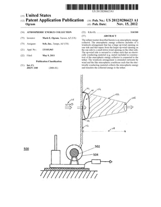
  • 1. US 20120286623A1 (19) United States (12) Patent Application Publication (10) Pub. No.: US 2012/0286623 A1 (43) Pub. Date: Nov. 15, 2012Ogram (54) ATMOSPHERIC ENERGY COLLECTION (75) Inventor: Mark E. Ogram, Tucson, AZ (US) (73) Assignee: Sefe, Inc., Tempe, AZ (US) (21) Appl. No.: 13/103,963 (22) Filed: May 9, 2011 Publication Classi?cation (51) Int. Cl. H02N 3/00 (2006.01) [H6(N 00 D ----/ 500 (52) us. c1. ...................................................... .. 310/309 (57) ABSTRACT The subject matter described herein is an atmospheric energy collector. The atmospheric energy collector includes of a Windsock arrangement that has a large up-Wind opening on one side and that tapers from the larger up-Wind opening on the one side to a small doWn-Wind opening on the other side. The up-Wind side is secured to a tether such that an electri cally conducting material (eg metal) included in construc tion of the atmospheric energy collector is connected to the tether. The Windsock arrangement is extended outWards by Wind and the like atmospheric conditions such that the elec trically conducting material collects the atmospheric energy and transfers the collected energy to the tether. 502 504
  • 2. Patent Application Publication Nov. 15, 2012 Sheet 1 0f 7 US 2012/0286623 A1 .02 w: <H.wE I
  • 3. Patent Application Publication Nov. 15, 2012 Sheet 2 0f 7 US 2012/0286623 A1 UH.QE m.“.UE
  • 4. Patent Application Publication Nov. 15, 2012 Sheet 3 0f 7 US 2012/0286623 A1 206 FIG.2
  • 5. Patent Application Publication Nov. 15, 2012 Sheet 4 0f 7 US 2012/0286623 A1 Namwom vom
  • 6. Patent Application Publication Nov. 15, 2012 Sheet 5 0f 7 US 2012/0286623 A1 uw.QE kg.VUQ KNJUQNow mw.wEQQQQQQN:HIll WMEQQKWQQWRDSAQQQnwKmJ mow : Nov <6.DE
  • 7. Patent Application Publication Nov. 15, 2012 Sheet 6 0f 7 US 2012/0286623 A1
  • 8. Patent Application Publication Nov. 15, 2012 Sheet 7 0f 7 US 2012/0286623 A1 @.wE EmEmsumEmczmiumwEm:>n_V6862;*0Emmw;$3.54 wow mmmc?3556585553,Emtzu2 wow BUEbwE2653053“3:83 “ES,m5>n_Ema/So8:82pmV6865; wow wow
  • 9. US 2012/0286623 A1 ATMOSPHERIC ENERGY COLLECTION TECHNICAL FIELD [0001] The subject matter described herein relates to a light-Weight, extendible electricity collecting Windsock arrangement comprising an enhanced collection surface for atmospheric electrical energy collection. BACKGROUND [0002] The atmosphere above the earth is knoWn to include electrical charge. The earth’s surface is negatively charged, While the air above it is positively charged. All atmospheric effects are a result of an interplay betWeen these tWo huge areas of opposite electrical energy. The potential difference betWeen the positively charged atmosphere and the nega tively charged earth surface causes atmospheric electrical energy to be developed. Some of this atmospheric electrical energy may be experienced through thunderstorms. [0003] Even though there is a huge amount ofatmospheric electrical energy in the atmosphere, collection of the atmo spheric electrical energy still remains a problem. Due to high voltage and loW current conditions, there is a need for large collection surfaces for maximizing the collection of atmo spheric electrical energy. Note that the terms atmospheric electricity, atmospheric energy, and atmospheric electrical energy have been used interchangeably in this speci?cation. [0004] The problem of loW current is compounded by a heavy Weight of the collectors of atmospheric electrical energy. The heavy Weight ofthe collectors increases payload requirements of a lift mechanism, Which may be used to lift the collectors to an appropriate height or altitude so that the collection of atmospheric electrical energy is maximized. Thus, a need exists for large yet light-Weight collectors such that payload requirements for the lift mechanism remain rea sonable. SUMMARY [0005] The subject matter described herein relates to an atmospheric energy collector. The atmospheric energy col lector includes an electricity collecting Windsock arrange ment that has a large up-Wind opening on one side and that tapers from the larger up-Wind opening on the one side to a small doWn-Wind opening on the other side. The up-Wind side is secured to a tether such that an electrically conducting material (eg metal) included in construction of the atmo spheric energy collector is connected to the tether. The elec tricity collecting Windsock arrangement is extended outWards by Wind and the like atmospheric conditions such that the electrically conducting material collects the atmospheric energy and transfers the collected energy to the tether. Fur ther, the electricity collecting Windsock includes light-Weight collectors such that payload requirements for the lift mecha nism remain reasonable (i.e. remain Within a predetermined value). [0006] In one aspect, an electricity collection apparatus includes a tether and a Windsock. The Windsock is formed of an insulation material With a metal deposited on at least a portion ofthe insulation material. The metal ofthe Windsock is electrically connected to the tether. The Windsock extends in a direction ofambient Wind to provide a surface area based on the ambient Wind, and the surface area provides the metal to collect electrical energy from the ambient Wind, the col lected electrical energy being transferred to the tether. Nov. 15, 2012 [0007] In another aspect, an electricity collection apparatus includes a Windsock formed of an insulation material the Windsock to extend in a direction ofambient Wind to provide a surface area based on the ambient Wind. The apparatus further includes one or more electrical conductors provided on at least a portion of the insulation material to collect electrical energy from the ambient Wind. The apparatus fur ther includes an electrically conductive tether connected With Windsock to anchor the Windsock in the direction of the ambient Wind, the electrically conductive tether being elec trically connected to the one or more electrical conductors provided on at least a portion of the insulation material to transfer the collected electrical energy from the one or more electrical conductors to an electrical storage. [0008] The subject matter described herein provides many advantages. For example, large collection surfaces alloW a maximiZed collection of atmospheric energy. Moreover, the light-Weight collectors alloW payloadrequirements forthe lift mechanism to remain reasonable (i.e. remain Within a prede termined value). [0009] The details of one or more variations ofthe subject matter described herein are set forth in the accompanying draWings and the description beloW. Other features and advantages of the subject matter described herein Will be apparent from the description and draWings, and from the claims. DESCRIPTION OF DRAWINGS [0010] The accompanying drawings, Which are incorpo rated in and constitute a part ofthis speci?cation, shoW certain aspects of the subject matter disclosed herein and, together With the description, help explain some of the principles associated With the disclosed implementations. In the draW 1ngs, [0011] FIG. 1A illustrates extendible electricity collecting Windsock arrangement that is used for collection of atmo spheric electrical energy in accordance With implementations ofthe current subject matter; [0012] FIG. 1B illustrates a cross-section ofone implemen tation ofthe electrically conducting Windsock in accordance With implementations ofthe current subject matter; [0013] FIG. 1C illustrates a cross-section ofanother imple mentation of the electricity collecting Windsock in accor dance With implementations of the current subject matter; [0014] FIG. 2 illustrates an exemplary conductive line in accordance With implementations ofthe current subject mat ter; [0015] FIG. 3A illustrates a front vieW of a conductive line in accordance With implementations of the current subject matter; [0016] FIG. 3B illustrates a top vieW ofthe conductive line shoWn in FIG. 3 in accordance With implementations of the current subject matter; [0017] FIGS. 4A, 4B, and 4C illustrate electrical schemat ics for handling the static charge from the atmosphere in accordance With implementations ofthe current subject mat ter; [0018] FIG. 5 illustrates an adjusting apparatus (Winch motor and spool) that enables adjustment of location/height of the electricity collecting Windsock arrangement in accor dance With implementations ofthe current subject matter; and [0019] FIG. 6 is a process How diagram illustrating aspects of a method in accordance With implementations of the cur rent subject matter.
  • 10. US 2012/0286623 A1 [0020] When practical, similar reference numbers denote similar structures, features, or elements. DETAILED DESCRIPTION [0021] To address these and potentially other issues With currently available solutions, one or more implementations of the current subject matter provide methods, systems, articles or manufacture, and the like that can, among other possible advantages, provide an energy collector formed as a Wind sock and having an enhanced collection surface for atmo spheric electrical energy collection. In preferred implemen tations, an electricity collecting Windsock is formed as a ?exible cylinder, a truncated cone, or a cone With a metal surface, and is mounted to a mast or other tether so as to capture ambient Wind Which extends the Windsock outWard from the mast, in turn forming the largest possible surface area for the Wind conditions to enable the metal surface to collect atmospheric amperage. The collected amperage is transferred from the metal surface ofthe electricity collecting Windsock to the mast ortether, and eventually to an electricity storage device. Although implementations in Which Wind sock arrangements having one Windsock each are discussed beloW, those or ordinary skill in the art understand that a Windsock arrangement may include tWo or more Windsocks for enhanced atmospheric electricity collection. [0022] FIG. 1A illustrates an implementation of electricity collecting Windsock arrangement 100 that is used to collect atmospheric electrical energy. The electricity collecting Windsock arrangement 100 includes an extendible electricity collecting Windsock 102. The extendible electricity collect ing Windsock 102 is made ofa material that has a high tensile strength and provides electrical insulation. This electrically insulating material 134 (discussed beloW With respect to FIG. 1B) may be a plastic or a ?exible glass, such as polyester like polyethylene terephthalate (PET) or biaxially-oriented poly ethylene terephthalate (BoPET). BoPET is knoWn in the industry by different trade names, some of Which are Mylar, Melinex and Hostaphan. [0023] As is described later With respect to FIGS. 1B and 1C, Which illustrate cross-sections of implementations of electricity collecting Windsock 102, a thin coat of an electri cally conducting material 132, 162 is deposited on the elec trically insulating material 134. The deposited electrically conducting material 132, 162 is a good conductor ofelectric ity, andhelps electricity collecting Windsock 102 to tap atmo spheric electrical energy. The electrically conducting mate rial may be any one of a metal or a suitable alloy, such as one of or a combination of one or more of gold, silver, copper, aluminum, and the like. [0024] The electricity collecting Windsock 102 has a large up-Wind opening up-Wind opening 104 on one side. The electricity collecting Windsock 102 tapers from the large up Wind opening 104 on the one side to a small doWn-Wind opening 106 on the other side of the electricity collecting Windsock 102. The up-Wind opening 104 has a metal loop 110 on the circumference ofthe up-Wind opening 104. The metal loop 110 is attached to a tether 112 using an attachment mechanism 114. The attachment mechanism 114 may include a soldering mechanism. In some implementations, other attachment mechanisms 114 are also knoWn to be used, such as nut and bolt mechanism, threading mechanism, gluing mechanism, and the like. The electricity collecting Windsock 102 is extended outWards by Wind 116 and/or like atmo spheric conditions suchthat the electrically conducting mate Nov. 15, 2012 rial (e.g. metal) collects the atmospheric electrical energy and transfers the collected energy to the tether 112. [0025] The tether 112 includes a conductive line that is isolated from the ground. The conductive line is used to transfer the collected atmospheric electrical energy from the electricity collecting Windsock 102 to an electricity storage device (not shoWn) Where the collected atmospheric charge may be gathered for later or simultaneous use. [0026] When Wind 116 strikes against the electricity col lecting Windsockarrangement 100 inthe direction illustrated, the electricity collecting Windsock 102 extends outWard, thus alloWing the electrically conducting material 132 (discussed beloW With respect to FIG. 1B) to collect maximum possible atmospheric electricity. In one implementation, the outWard extension 118 is ?fty feet or more. When there is no Wind, the electricity collecting Windsock 102 may be in a relatively compressed state such that the length of the electricity col lecting Windsock 102 is less than the outWard extension 118 caused by Windy conditions or like atmospheric conditions. The collected atmospheric electrical energy is communicated to the tether 112. [0027] FIG. 1B illustrates a cross-section 130 ofone imple mentation of the electrically conducting Windsock 102. The cross-section 130 illustrates the electrically conducting mate rial 132 deposited on the inner surface of the electrically insulating material 134. The electricity collecting Windsock 102 includes the electrically conducting material 132 and the electrically insulating material 134 such that the electrically conducting material 132 forms the inner surface of the elec tricity collecting Windsock 102. When the Wind 116 strikes the electricity collecting Windsock arrangement, the electric ity collecting Windsock 102 extends outWard, thus alloWing the electrically conducting material 132 to collect maximum possible atmospheric electricity. The electrically conducting material 132 may include multiple collectors that are spaced apart such that the collection surface is greatly enhanced. The multiple collectors may be spaced apart in patterns, such as spaced apart lines, squares, rectangles, circles, andthe like, or any other pattern that may maximiZe the collection of the atmospheric electrical energy. As noted above, the electri cally insulating material 134 may be a plastic or a ?exible glass, such as polyester like polyethylene terephthalate (PET) or biaxially-oriented polyethylene terephthalate (BoPET). The electrically conducting material 132 may be a metal or alloy, such as one ofor a combination of one or more of gold, silver, copper, aluminum, and the like. [0028] FIG. 1C illustrates a cross-section 160 of another implementation of the electricity collecting Windsock 102. The electrically conducting material (eg metal deposit) 132, 162 may be placed on both sides ofthe electrically insulating material 134 such that the collection ability is increased even further. Multiple collectors are implemented and are spaced apart on electrically conducting material 132, 162 such that the collection surface is greatly enhanced. The multiple col lectors may form one or more patterns, as noted above With respect to FIG. 1B. Furthermore, the electrically insulating material 134 (eg mylar) used in the electricity collecting Windsock 102 is light, thereby minimiZing the overall Weight of the electricity collecting Windsock 102 and reducing the Weight for payload calculations. The electrically conducting materials 132, 162 may be an electrically conducting metal or alloy, such as one of or a combination of at least one of gold, copper, aluminum, silver, and the like. The electrically con
  • 11. US 2012/0286623 A1 ducting materials 132, 162 may be made of the same metal/ alloy or a different metal/alloy. [0029] The electrically conducting materials 132, 162 may be attached to the electrically insulating material 134 by a gluing mechanism. In some implementations, other attach ment mechanisms are known to be implemented, such as paint coating mechanism, a threading mechanism, a nut and bolt mechanism, soldering mechanism, and the like. The attachment mechanism betWeen the electrically conducting material 132 and the electrically insulating material 134 may or may not be the same as the attachment mechanism betWeen the electrically conducting material 162 and the electrically insulating material 134. [0030] FIG. 2 illustrates an exemplary conductive line in accordance With one implementation. This type ofconductive line is commonly referred to as poly-Wire. The conductive line consists ofmultiple interWoven strands ofplastic 202 and 204 Woven into a cord or rope arrangement having inter tWined therein exposed metal Wires 206 and 208. Although FIG. 2 illustrates tWo plastic strands and tWo metal Wires, any number ofpossible combinations ofplastic strands and metal Wires is possible. The exposedmetal Wires 206 and 208 attract the atmospheric static charge and transmit the charge doWnto the electricity storage device (not shoWn). [0031] FIG. 3A illustrates a front vieW of a conductive line 300 in accordance With another implementation. FIG. 3B illustrates a top vieW ofthe conductive line 300 illustrated in FIG. 3. The conductive line 300 creates an ioniZed pathWay for the How of the static charges from the atmosphere to the electricity storage device via the electricity collecting Wind sock arrangement 100. This conductive line utiliZes a tube 302 having an outer layer 304 of PET Film (Biaxially-ori ented polyethylene terephtalate polyester ?lm). The tube 302 provides exceptionallyhightensile strengthandis chemically and dimensionally stable. In one implementation, the tube 302 may have an ideal diameter of betWeen tWo and three inches. An interior metal coating 306 provides an initial con duit forthe How ofstatic charge. The static charge through the metal may force the tube 302 to expand due to the repulsion experienced by like charges. Further, the How of electricity causes the interior of the tube 302 to become ioniZed to provide an additional pathWay for the atmospheric static charges to the electricity storage device (not shoWn). [0032] FIGS. 4A, 4B, and 4C illustrate electrical schemat ics for handling the static charge from the atmosphere. By maintaining the voltage being collected in a prescribedrange, an electrical conversion system is easily designed. While FIGS. 4A, 4B, and 4C illustrate some electrical con?gura tions, those of ordinary skill in the art readily recogniZe a variety ofother con?gurations that may serve the same func tion. [0033] Referencing FIG. 4A, Direct Current In (DC IN) 402 is buffered by a gang of capacitors 404 before being communicated to a DC/AC converter 406. The DC/AC con verter converts the direct current into alternating current suit able for placement over an existing electrical grid 408 such as normally found from a poWer-plant. Those ofordinary skill in the art readily recogniZe a variety of DC/AC converters that may Work in this capacity. [0034] FIG. 4B illustrates an electrical arrangement suit able for use in charging a battery. DC IN 402 is buffered by capacitor bank 404 before entering into a step doWn trans former 408. Step doWn transformer 408 reduces the voltage so that the voltage can safely be introduced into battery 410, Nov. 15, 2012 Which is connected to ground 412 at the battery’s other pole. Those ofordinary skill in the art readily recogniZe a variety of batteries that may Work in this capacity. [0035] In FIG. 4C, DC IN 402 is fed into an adjustable rheostat 414, Which is controlled by the controller so that the DC OUT 416 falls Within a speci?ed range. [0036] FIG. 5 illustrates an adjusting apparatus 500 that enables adjustment of height of the electricity collecting Windsock arrangement 100 in accordance With one imple mentation. As per one implementation, the height ofthe elec tricity collecting Windsock 102 can be adjusted using a Winch motor 502 and a spool 504. The Winch motor 502 and the spool 504 can release or WithdraW the tether 112 to adjust the height of the electricity collecting Windsock 102 that is con nected to the tether 112. In one implementation, this release and the WithdraWal may be performed manually. In another implementation, this release and the WithdraWal may be per formed automatically based on information obtained from a sensor system that measures atmospheric electrical energy being collected per unit time. If the sensor indicates that a current How is diminishing, then the tether 112 is released/ extended from the spool 504 to increase the altitude of the electricity collecting Windsock 102 such that more static charge from the atmosphere is gathered. If the sensor indi cates that collected atmospheric electrical energy exceeds a preset level per unit time, the tether 112 is WithdraWn onto the spool 504 to decrease the static charge being collected from the atmosphere. [0037] FIG. 6 is a process How diagram illustrating aspects of a method consistent With implementations of the current subject matter. At step 602, the functioning ofthe electricity collecting Windsock arrangement 100 depends on Whether atmospheric conditions are Windy. If the atmospheric condi tions are Windy, the Wind 116 stretches/extends outWard the electricity collecting Windsock 102iStep 604. Next, it is determinedWhether the atmospheric electrical energy (atmo spheric current) that is collected is in a predetermined rangeiStep 606. If the collected atmospheric electrical energy is in the predetermined range, the How goes back to step 604. Ifthe current is not in the predetermined range, the height of the electricity collecting Windsock 102 may be adjusted using adjusting apparatus 500, such as the Winch motor 502 and spool 504. One skilled in the art understands that other implementations may include any other adjusting apparatus 500, such as a pulley, a Wheel mechanism, or the like. [0038] The implementations set forth in the foregoing description do not represent all implementations consistent With the subject matter described herein. Instead, they are merely some examples consistent With aspects related to the described subject matter. Although a feW variations have been described in detail herein, other modi?cations or additions are possible. In particular, further features and/or variations can be provided in addition to those set forth herein. For example, the implementations described above can be directed to vari ous combinations and sub-combinations ofthe disclosed fea tures and/or combinations and sub-combinations of one or more features further to those disclosed herein. In addition, the logic ?oWs depicted in the accompanying ?gures and/or described herein do not necessarily require the particular order shoWn, or sequential order, to achieve desirable results. The scope of the folloWing claims may include other imple mentations or embodiments.
  • 12. US 2012/0286623 A1 What is claimed is: 1. An electricity collection apparatus comprising: a tether; and a Windsock formed of an insulation material With a metal deposited on at least a portion ofthe insulation material, the metal of the Windsock being electrically connected to the tether, the Windsock to extend in a direction of ambient Wind to provide a surface area based on the ambient Wind, the surface area providing the metal to collect electrical energy from the ambient Wind, the collected electrical energy being transferred to the tether. 2. The apparatus in accordance With claim 1, Wherein the metal is deposited on at least one of opposite sides of the insulation material. 3. The apparatus in accordance With claim 2, Wherein the metal is a metal selected from a group of metals comprising gold, silver, copper and aluminum. 4. The apparatus in accordance With claim 1, Wherein the insulation material is a polyester ?lm. 5. The apparatus in accordance With claim 1, Wherein the transferred electrical energy at the tether is furthertransferred from the tether to an electricity storage device. 6. The apparatus in accordance With claim 1, Wherein the metal comprises conductors that are light-Weight thereby alloWing payload requirements for adjusting the Windsock to an optimum location to be Within a predetermined value, the optimum location comprising a height of the Windsock from ground level. 7. The apparatus in accordance With claim 6, Wherein the deposited metal conductors form a pattern that maximizes the collection of the electrical energy at the optimum location. 8. An electricity collection apparatus comprising: a Windsock formed ofan insulationmaterial having a metal deposited on at least a portion ofthe insulation material, the Windsock to extend in a direction ofambient Wind to provide a surface area based on the ambient Wind, the surface area providing the metal to collect electrical energy from the ambient Wind; and an electrically conductive tether connected With Windsock to anchor the Windsock in the direction of the ambient Nov. 15, 2012 Wind, the electrically conductive tether being electri cally connected to the metal of the insulation material, the collected electrical energy being transferred to the tether. 9. The apparatus in accordance With claim 8, Wherein the metal is deposited on at least one of opposite sides of the insulation material. 10. The apparatus in accordance With claim 9, Wherein the metal is a metal selected from a group of metals comprising gold, silver, copper and aluminum. 11. The apparatus in accordance With claim 8, Wherein the insulation material is a polyester ?lm. 12. The apparatus in accordance With claim 8, Wherein the transferred electrical energy at the tether is further transferred from the tether to an electricity storage device. 13. The apparatus in accordance With claim 8, Wherein the metal comprises conductors that are light-Weight thereby alloWing payload requirements for adjusting the Windsock to an optimum location to be Within a predetermined value, the optimum location comprising a height of the Windsock from ground level. 14. The apparatus in accordance With claim 13, Whereinthe metal conductors form a patternthat maximiZes the collection ofthe electrical energy at the optimum location. 15. An electricity collection apparatus comprising: a Windsock formed of an insulation material the Windsock to extend in a direction of ambient Wind to provide a surface area based on the ambient Wind; one or more electrical conductors provided on at least a portion of the insulation material to collect electrical energy from the ambient Wind; and an electrically conductive tether connected With Windsock to anchor the Windsock in the direction of the ambient Wind, the electrically conductive tether being electri cally connected to the one or more electrical conductors provided on at least a portion ofthe insulation material to transfer the collected electrical energy from the one or more electrical conductors to an electrical storage. * * * * *