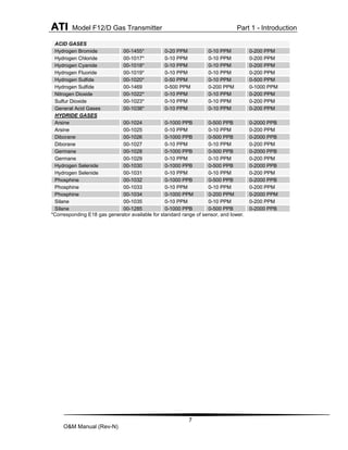
Download to read offline


![2
O&M Manual (Rev-N)
Table of Figures
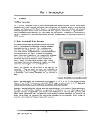
FIGURE 1- TRANSMITTER W/SENSOR & GENERATOR .... 5
FIGURE 2. ENCLOSURE DIMENSIONS, (RS485 NO
RELAYS).......................................................... 9
FIGURE 3 DEEP ENCLOSURE DIMENSIONS ................. 10
FIGURE 4 WALL/PIPE MOUNTING BRACKET................. 10
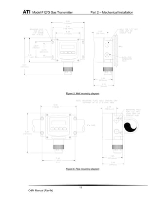
FIGURE 5. WALL MOUNTING DIAGRAM ....................... 11
FIGURE 6. PIPE MOUNTING DIAGRAM......................... 11
FIGURE 7. PANEL MOUNTING DETAILS [DEEP CASE]..... 12
FIGURE 8 DUCT MOUNT SENSOR EXPLODED VIEW..... 13
FIGURE 9. DUCT-MOUNT ASSEMBLY .......................... 13
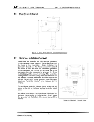
FIGURE 10 - DUCT MOUNT (INTEGRAL) TRANSMITTER
DIMENSIONS.................................................. 14
FIGURE 11 - GENERATOR EXPLODED VIEW ............... 14
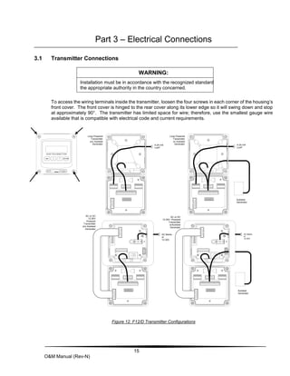
FIGURE 12. F12/D TRANSMITTER CONFIGURATIONS .. 15
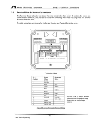
FIGURE 13. SENSOR/GENERATOR TERMINAL WIRING. 16
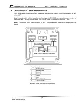
FIGURE 14. POWER AND COMMUNICATION TERMINALS.17
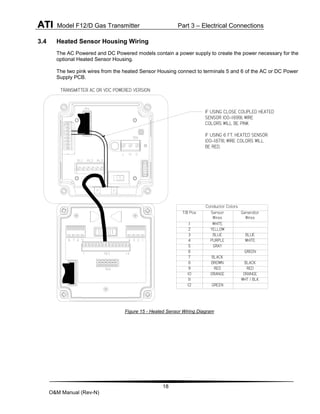
FIGURE 15 - HEATED SENSOR WIRING DIAGRAM ....... 18
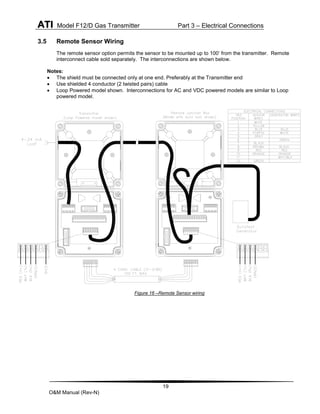
FIGURE 16 –REMOTE SENSOR WIRING...................... 19
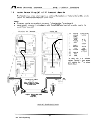
FIGURE 17 –REMOTE SENSOR WIRING...................... 20
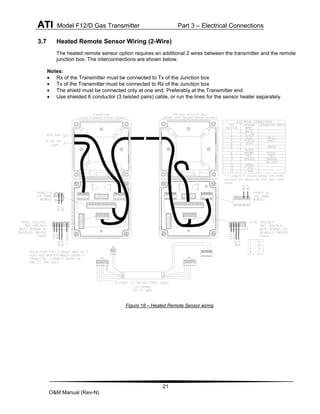
FIGURE 18 – HEATED REMOTE SENSOR WIRING ........ 21
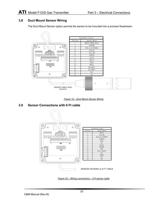
FIGURE 19 – DUCT MOUNT SENSOR WIRING............. 22
FIGURE 20 – WIRING CONNECTIONS – 6 FT SENSOR
CABLE........................................................... 22
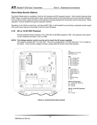
FIGURE 21 - POWERED ALARM RELAY CONTACTS...... 23
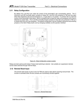
FIGURE 22 - RELAY CONFIGURATION JUMPER LOCATION
.................................................................... 24
FIGURE 23 – REMOTE RESET INPUT ......................... 24
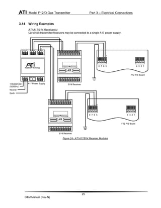
FIGURE 24 - ATI A17/B14 RECEIVER MODULES........ 25
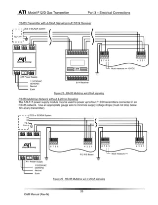
FIGURE 25 - RA485 MULTIDROP W/4-20MA SIGNALING
.................................................................... 26
FIGURE 26 - RS485 MULTIDROP W/O 4-20MA
SIGNALING..................................................... 26
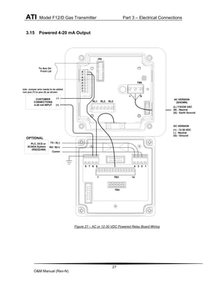
FIGURE 27 – AC OR 12-30 VDC POWERED RELAY
BOARD WIRING.............................................. 27
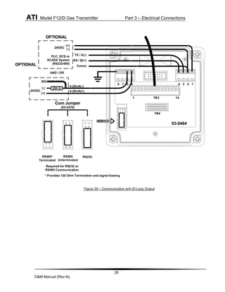
FIGURE 28 – COMMUNICATION W/4-20 LOOP OUTPUT 28
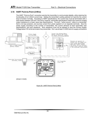
FIGURE 29 - HART POINT-TO-POINT (2-WIRE) ......... 29
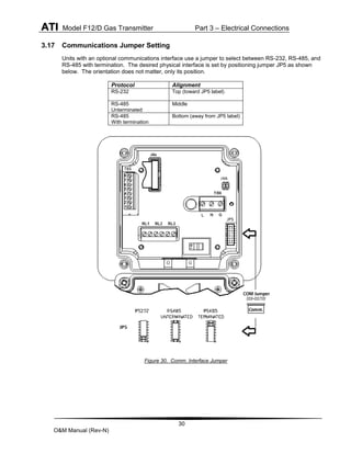
FIGURE 30. COMM. INTERFACE JUMPER................... 30
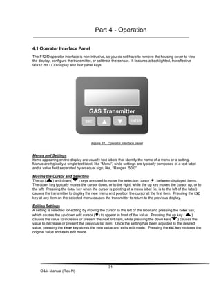
FIGURE 31. OPERATOR INTERFACE PANEL ................ 31
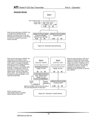
FIGURE 32. EXAMPLE EDIT ..................................... 32
FIGURE 33. TRANSMITTER REVIEW DISPLAYS ........... 32
FIGURE 34. SENSOR REVIEW DISPLAY..................... 33
FIGURE 35 - GENERATOR NORMAL REVIEW............... 34
FIGURE 36 - GENERATOR TROUBLE REVIEW ............. 34
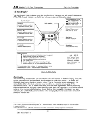
FIGURE 37. MAIN DISPLAY...................................... 35
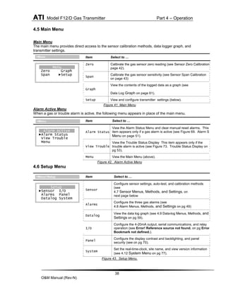
FIGURE 38. MAIN DISPLAY TROUBLE INDICATION ...... 36
FIGURE 39. SENSOR REMOVED DISPLAY.................. 36
FIGURE 40. GENERATOR REMOVED DISPLAY............ 37
FIGURE 41. MAIN MENU .......................................... 38
FIGURE 42. ALARM ACTIVE MENU............................ 38
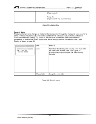
FIGURE 43. SETUP MENU. ...................................... 38
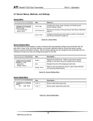
FIGURE 44. SENSOR MENU. ....................................39
FIGURE 45. SENSOR SETTINGS MENU ......................39
FIGURE 46. SENSOR MODEL MENU ..........................39
FIGURE 47. SENSOR RANGE MENU ..........................40
FIGURE 48. DATA-LOG WARNING MESSAGE ..............40
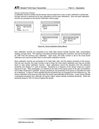
FIGURE 49. SENSOR CALIBRATION MENU..................42
FIGURE 50. SENSOR ZERO CAL. SETUP....................42
FIGURE 51. SENSOR ZERO CAL.MENUS....................42
FIGURE 52 SENSOR SPAN CAL. SETUP.....................43
FIGURE 53. SENSOR SPAN CAL. MENUS ...................43
FIGURE 54. SENSOR CALIBRATION HISTORY MENUS ..44
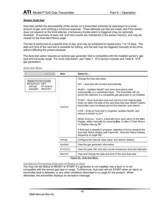
FIGURE 55. AUTO-TEST MENU .................................45
FIGURE 56. AUTO-TEST SETUP MENU.......................46
FIGURE 57. AUTO-TEST SETUP OPTIONS MENU.........46
FIGURE 58. AUTO-TEST NEXT AT MENU ...................46
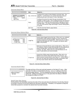
FIGURE 59. AUTO-TEST HISTORY MENU ...................47
FIGURE 60. GAS GENERATOR DISPLAY.....................47
FIGURE 61. AUTO-TEST STATUS DISPLAY .................47
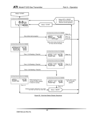
FIGURE 62. AUTO-TEST STATUS DISPLAY SEQUENCE.48
FIGURE 63. ALARMS MENU......................................49
FIGURE 64. TOXIC GAS ALARMS. .............................49
FIGURE 65. OXYGEN DEFICIENCY ALARMS................49
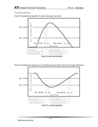
FIGURE 66. HIGH ALARM OPERATION .......................50
FIGURE 67. LOW ALARM OPERATION........................50
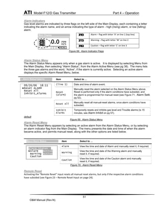
FIGURE 68. ALARM INDICATOR FLAGS.......................51
FIGURE 69. ALARM STATUS MENU ...........................51
FIGURE 70. ALARM RESET MENU .............................51
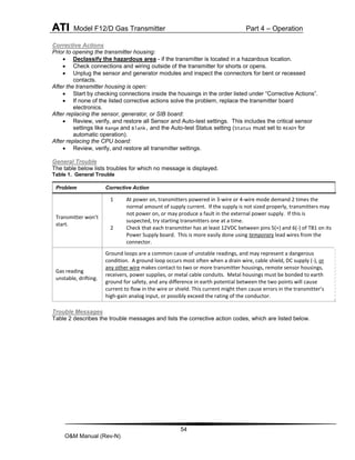
FIGURE 71. ALARM SETTING MENUS ........................52
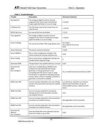
FIGURE 72. TROUBLE INDICATION ON MAIN DISPLAY ..53
FIGURE 73. TROUBLE STATUS DISPLAY ....................53
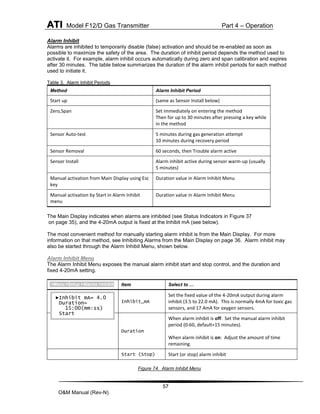
FIGURE 74. ALARM INHIBIT MENU.............................57
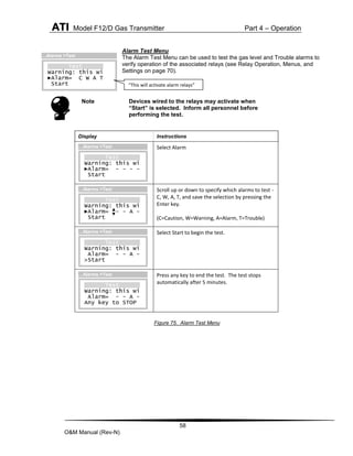
FIGURE 75. ALARM TEST MENU ...............................58
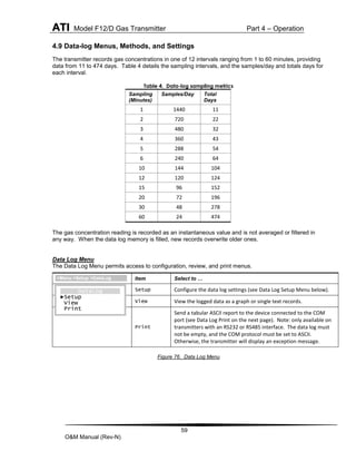
FIGURE 76. DATA LOG MENU...................................59
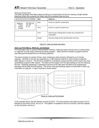
FIGURE 77. DATA LOG SETUP MENU ........................60
FIGURE 78. DATA LOG VIEW MENU ..........................60
FIGURE 79. DATA LOG GRAPH VIEW.........................61
FIGURE 80. DATA LOG GRAPH VIEW MENU ...............61
FIGURE 81. DATA LOG SINGLE VIEW MENU...............62
FIGURE 82. DATA LOG PRINT EXAMPLE ....................62
FIGURE 83. DATA LOG PRINT MENU .........................63
FIGURE 84. DATA LOG PRINT FORMAT MENU ............63
FIGURE 85. I/O MENU .............................................64
FIGURE 86. GRAPH OF 4-20MA OUTPUT...................64
FIGURE 87. 4-20MA MENU......................................65
FIGURE 88. 4-20MA CONTROL PAGE.........................65
FIGURE 89. ADJUST 4MA MENU...............................65
FIGURE 90. ADJUST 20MA MENU.............................66
FIGURE 91. COM MENU .........................................66
FIGURE 92. COM SETUP MENU...............................67
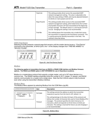
FIGURE 93. HART MENU.........................................68](https://image.slidesharecdn.com/atif12d-rev-n-230608145633-9e0a6f96/85/ATI_F12D-Rev-N-pdf-3-320.jpg)
![ATI Model F12/D Gas Transmitter Part 2 – Mechanical Installation
12
O&M Manual (Rev-N)
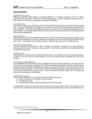
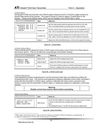
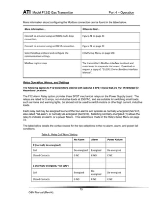
2.4 Panel Mounting (Remote Sensors Only)
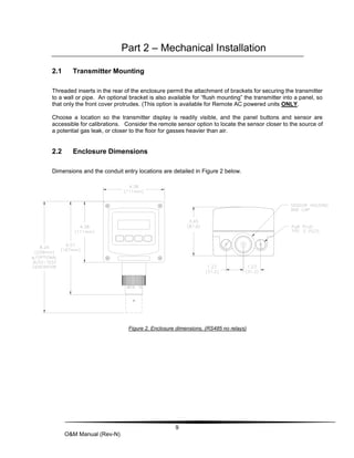
Figure 7 depicts the details for panel mounting the deep case. For this, a bracket attaches to the rear
housing, and when adjusted, pulls the transmitter’s flange down against the adhesive side of the gasket
supplied with the bracket (make certain to remove the protective paper first).
Figure 7. Panel mounting details [deep case]
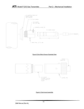
2.5 Duct Sensor Mounting
The H10 sensor duct mount option allows sensors to be installed in a duct or pipe, and provides easy
access for service.
The assembly is comprised of a special H10 sensor holder that slides into the hollow duct mount
adapter (See Figure 9). The adapter has 1-1/2” MNPT threads on the insertion end, for securing it
to the duct or pipe, and a barb fitting for supplying calibration gas to the sensor. An interface cable
is provided to connect the sensor holder to the transmitter. Note that a mating flange for securing
the adapter is not provided.
Screw the adapter into the duct or pipe so the barb fitting is accessible to connect gas tubing. Once
the adapter is in place, slide in the sensor holder, lock it in place, and connect the interface cable. It
is recommended that the sensor not be installed in the holder until you are ready to start the
transmitter. This is especially true during construction, when excessive dust and dirt may be blowing
through the duct system and be deposited on the sensor.](https://image.slidesharecdn.com/atif12d-rev-n-230608145633-9e0a6f96/85/ATI_F12D-Rev-N-pdf-13-320.jpg)
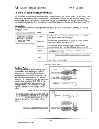


The document is an operation and maintenance manual for the F12/D toxic gas transmitter equipped with H10 smart sensor technology, detailing installation, operation, and maintenance guidelines. It includes sections on safety, mechanical installation, electrical connections, operational menus, and maintenance procedures. The manual also provides specifications and various operational settings for monitoring different gases in industrial environments.