Assessment and reinforcement of the 20 existing bridges in the Bozoum-Bossangoa road in Central African Republic. Presentation to the Ministry of Works.
Assessment and reinforcement of the 20 existing bridges included in the rehabilitation of 137 km of rural road between Bozoum and Bossangoa in Central African Republic. Presentation to the Ministry of Works.
RESTORATION OF EXISTING MAJOR BRIDGE ACROSS RIVER BHADAR ON NATIONAL HIGHWAY ...IEI GSC
By S.K.Patel, P C Gandhi S R Shah J N Prajapati
at 31st National Convention of Civil Engineers
organised by
Gujarat State Center, The Institution of Engineers (India) at Ahmedabad
RESTORATION OF EXISTING MAJOR BRIDGE ACROSS RIVER BHADAR ON NATIONAL HIGHWAY ...IEI GSC
By S.K.Patel, P C Gandhi S R Shah J N Prajapati
at 31st National Convention of Civil Engineers
organised by
Gujarat State Center, The Institution of Engineers (India) at Ahmedabad
The first presentation of a series of presentations on Operations Geology. Very basic, just to introduce beginners to operations geology. I hope the end users will find this and the following presentations very helpful.
Analysis and Design Aspects of Support Measures of Main Caverns of Karuma Hyd...IOSRJMCE
The Power house complex of Karuma Hydropower project comprises three main caverns i.e Power house, Transformer Hall and Tailrace surge gallery set at a depth of about 80m in mainly granitic gneiss rock medium. The cavern has been oriented in a N141° direction based on engineering considerations. The principle stress direction is also found nearly parallel to the axis of the caverns and thus the present orientation satisfies both engineering and geotechnical criteria. The support by way of rock anchors and SFRS/ Plain shotcrete has been provided based on analysis using phase 2 software. The underground caverns lie in low geostress field and therefore numerical simulation of excavation of these caverns were done to understand the rock mass behavior during excavation and thus help in design of excavation sequence and rock support. The excavation of all three caverns has since been completed and concrete works are in progress. This paper sums up the 3D simulation analysis of the rock medium and the proposed rock support system for the three caverns.
Combine piled raft foundation (cprf)_Er.Karan ChauhanEr.Karan Chauhan
Combine Piled Raft Foundation(CPRF) is an emerging type of new foundation techniques in High rise buildings and skyscraper which raft as a shallow foundation and pile as deep foundation works sharing the total load and reduce settlement and bending moment. the modern approach of design philosophy is included in post graduation level with soil structure interaction of CPRF and this will use to understand the basic concept regarding it.
The main components of an earth dam are as follows :
1. Impervious core
2. Pervious shell
3. Filter
4. Rock toe
5. U/S slope protection
6. D/S slope protection
7. Cutoff
core should not be less than 3 m and its height should be 1 m more than the maximum water level in the reservoir.
The upstream pervious zone provides free drainage during sudden drawdown. ,
Usually following types of filters are provided :
(1) Toe filter
(2) Horizontal drainage filter (blanket)
(3) Chimney drains
Such a filter is sometimes known as inverted filter or reverse filter.
Rock toe keeps the phreatic line well within the section and also facilitates drainage.
The following measures are taken to protect the slope.
(1) Rock riprap
(2) Concrete pavement
(3) Steel facing
(4) Bituminous pavement
(5) Precast concrete blocks
Cut off is required to
(1) reduce loss of stored water through foundation and abutments
(2) Prevent sub surface erosion by piping.
Cutoff may be provided in the following ways :
• by providing concrete cutoff wall
• by providing cutoff trench filled with impervious material
• by driving sheet pile
• by curtain grouting
A pile is basically a long cylinder of a strong material such as concrete that is pushed into the ground to act as a steady support for structures built on top of it.
Pile foundations are used in the following situations:
When there is a layer of weak soil at the surface. This layer cannot support the weight of the building, so the loads of the building have to bypass this layer and be transferred to the layer of stronger soil or rock that is below the weak layer.
When a building has very heavy, concentrated loads, such as in a high rise structure, bridge, or water tank.
The current drilled shaft (also called bored pile) foundation design procedures recommended in two commonly used North American foundation engineering manuals have been reviewed, and the recommended design approache from each manual is evaluated against the recent load test data conducted on continuous flight auger (CFA), cast-in-place concrete piles (augercast piles). The soil conditions where pile load tests were carried out is typical of glacial till encountered in the Canadian Prairies. The conclusion is that pile capacity prediction methods widely used in North America generally under estimate both skin resistance and end bearing for drilled shaft in very stiff to hard glacial till. For design purpose, for drilled, cast in-place concrete piles installed in glacial till soils in Western Canada, procedure recommended by Federal Highway Administration (FHWA) is recommended.
Infrastructure Needs: North Dakota’s County, Township, & Tribal Roads & Bridg...UGPTI
Presentation to the ND Legislative Transportation Committee on Sept. 28, 2016: Infrastructure Needs: North Dakota’s County, Township, & Tribal Roads & Bridges 2017-2036.
Concrete Repair: Bridges and Tunnels--Epoxies jbors
Examples of maintenance, rehabilitation and repair of transportation structures including bridges and tunnels using epoxy products for structural repair and protection. ASTM C881 catagories are explained. ChemCo Systems, Redwood City, CA manufactures epoxies for these applications (www.chemcosystems.com).
Oldest branch of engineering, next to Military engineering. All engineering works other than for military purposes were grouped in to Civil Engineering. Mechanical, Electrical, Electronics & present day Information technology followed it.
A professional engineering discipline that deals with the analysis, design, construction and maintenance of infrastructural facilities such as buildings, bridges, dams, roads etc.
Civil Engineering is everywhere. Civil Engineering is a composite of many specific disciplines that include structural engineering, water engineering, waste material management and engineering, foundation engineering etc. among many.
Similar to Assessment and reinforcement of the 20 existing bridges in the Bozoum-Bossangoa road in Central African Republic. Presentation to the Ministry of Works.
In this you will find some of the basic thing regarding the elevated water tank and this is our one of the team project work in college. Hope you will enjoy it....
A presentation on the hydrogeology & water supply associated with the Rosemont Copper Project developed by the Erroll L. Montgomery & Associates, Inc. This presentation was given to the Forest Service and their contractors during technical transfer meetings in November 2008.
E-Book of worldwide locomotive Bogie and suspension system
Similar to Assessment and reinforcement of the 20 existing bridges in the Bozoum-Bossangoa road in Central African Republic. Presentation to the Ministry of Works. (20)
Assessment and reinforcement of the 20 existing bridges in the Bozoum-Bossangoa road in Central African Republic. Presentation to the Ministry of Works.
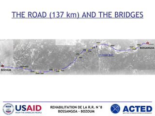
1. THE ROAD (137 km) AND THE BRIDGES
REHABILITATION DE LA R.R. N°8
BOSSANGOA – BOZOUM
BOSSANGOA
BOZOUM
OUHAM BAC
2. EXISTING BRIDGES - DESCRIPTION
REHABILITATION DE LA R.R. N°8
BOSSANGOA – BOZOUM
STEEL GIRDERS
TIMBER
DECKING
STONE MASONRY
ABUTMENTS
• THERE ARE 20 BRIDGES ON THE BOSSANGOA-BOZOUM ROAD
• THE CONSTRUCTION METHOD IS THE SAME FOR ALL THE
BRIDGES: TIMBER DECKING ON 4 STEEL GIRDERS WITH STONE
MASONRY ABUTMENTS
3. EXISTING BRIDGES - CONSERVATION STATE
• TIMBER DECKING
– ON THE BOSSANGOA SIDE, THE TIMBER DECKING IS STILL
IN POSITION, BUT GENERALLY IN POOR CONDITION.
– ON THE BOZOUM SIDE THE ORIGINAL DECKING HAS
COLLAPSED AND HAS BEEN REPLACED BY WOODEN
BRANCHES.
• STEEL GIRDERS
– THE CONDITION IS GOOD.
• MASONRY ABUTMENTS
– THE CONSERVATION IS GENERALLY GOOD, EXCEPT FOR 7
BRIDGES WITH CRACKS THAT REQUIRE REINFORCING.
REHABILITATION DE LA R.R. N°8
BOSSANGOA – BOZOUM
4. EXISTING BRIDGES - CONSERVATION STATE
PONT N° 16 (BOSSANGOA SIDE) – THE TIMBER DECKING
REHABILITATION DE LA R.R. N°8
BOSSANGOA – BOZOUM
5. EXISTING BRIDGES - CONSERVATION STATE
PONT N° 17 (BOSSANGOA SIDE) – THE TIMBER DECKING
REHABILITATION DE LA R.R. N°8
BOSSANGOA – BOZOUM
6. EXISTING BRIDGES - CONSERVATION STATE
PONT N° 19 (BOSSANGOA SIDE) – THE TIMBER DECKING
REHABILITATION DE LA R.R. N°8
BOSSANGOA – BOZOUM
7. EXISTING BRIDGES - CONSERVATION STATE
PONT N° 8 (BOZOUM SIDE) – THE TIMBER DECKING
REHABILITATION DE LA R.R. N°8
BOSSANGOA – BOZOUM
8. EXISTING BRIDGES - CONSERVATION STATE
PONT N° 10 (BOZOUM SIDE) – THE TIMBER DECKING
REHABILITATION DE LA R.R. N°8
BOSSANGOA – BOZOUM
9. EXISTING BRIDGES - CONSERVATION STATE
PONT N° 12 (BOZOUM SIDE) – THE TIMBER DECKING
REHABILITATION DE LA R.R. N°8
BOSSANGOA – BOZOUM
10. EXISTING BRIDGES - CONSERVATION STATE
PONT N° 20 (BOZOUM SIDE) – THE STEEL GIRDERS
REHABILITATION DE LA R.R. N°8
BOSSANGOA – BOZOUM
11. EXISTING BRIDGES - CONSERVATION STATE
PONT N° 4 (BOZOUM SIDE) – THE STEEL GIRDERS
REHABILITATION DE LA R.R. N°8
BOSSANGOA – BOZOUM
12. EXISTING BRIDGES - CONSERVATION STATE
PONT N° 7 (BOZOUM SIDE) – THE STEEL GIRDERS
REHABILITATION DE LA R.R. N°8
BOSSANGOA – BOZOUM
13. EXISTING BRIDGES - CONSERVATION STATE
PONT N° 4 (BOZOUM SIDE) – THE ABUTMENTS
REHABILITATION DE LA R.R. N°8
BOSSANGOA – BOZOUM
14. EXISTING BRIDGES - CONSERVATION STATE
PONT N° 16 (BOSSANGOA SIDE) – THE ABUTMENTS
REHABILITATION DE LA R.R. N°8
BOSSANGOA – BOZOUM
15. EXISTING BRIDGES - CONSERVATION STATE
PONT N° 20 (BOZOUM SIDE) – THE ABUTMENTS
REHABILITATION DE LA R.R. N°8
BOSSANGOA – BOZOUM
16. EXISTING BRIDGES - CONSERVATION STATE
PONT N° 3 (BOZOUM SIDE) – THE ABUTMENTS
REHABILITATION DE LA R.R. N°8
BOSSANGOA – BOZOUM
17. EXISTING BRIDGES - CONSERVATION STATE
PONT N° 18 (BOSSANGOA SIDE) – THE ABUTMENTS
REHABILITATION DE LA R.R. N°8
BOSSANGOA – BOZOUM
18. THE DESIGN
• GOAL OF THE DESIGN:
– REOPEN THE ROAD AND THE BRIDGES TO TRAFFIC IN A
SAFE, FAST AND COST-EFFECTIVE WAY. WE HAVE TRIED
TO CONSERVATE AND REUSE TO THE MAXIMUM THE
EXISTING BRIDGES, IDENTIFYING THE ALLOWABLE LOAD
OF THE STRUCTURES AND REINFORCEING THEM WHERE
NEEDED.
• METHOD OF WORK:
– FOR ALL THE BRIDGES WE HAVE CONDUCTED A
STRUCTURAL ANALYSIS WITH COMPUTER FINITE ELEMENT
MODELS TO DEFINE THE MAXIMUM LOAD THAT THE
BRIDGES CAN SUPPORT AND THEREFORE THE ALLOWABLE
LOAD OF THE ROAD. THE CALCULATIONS HAVE BEEN DONE
ACCORDING TO EUROCODES AND AASHTO “STANDARD
SPECIFICATIONS FOR HIGHWAY BRIDGES”.
REHABILITATION DE LA R.R. N°8
BOSSANGOA – BOZOUM
19. THE DESIGN – THE STRUCTURAL ANALYSIS
• DESIGN LOAD:
(FROM AMERICAN AASHTO CODES)
• THE MATERIALS:
– TIMBER: MUKULUNGU
– STEEL: ? FOR THE EXISTING GIRDERS WE HAVE NO
INFORMATION ON THE GRADE OF THE STEEL AND ITS
RESISTANCE. WE HAVE CONSERVATIVELY ASSUMED THAT
THE GIRDERS ARE MADE OF S235 STEEL (yielding strength
= 235 MPa) WHICH IS THE LOWEST OF THE 3 COMMERCIAL
STEEL GRADES (235, 275 O 355 MPa)
REHABILITATION DE LA R.R. N°8
BOSSANGOA – BOZOUM
20. THE DESIGN – THE STRUCTURAL ANALYSIS
REHABILITATION DE LA R.R. N°8
BOSSANGOA – BOZOUM
FINITE ELEMENT MODEL (2D) FINITE ELEMENT MODEL (3D)
BENDING MOMENT CALCULATED DEFLECTION
MAXIMUM
CALCULATED
DEFLECTION
21. THE DESIGN – CONCLUSIONS
• REPLACE THE TIMBER DECKING FOR ALL BRIDGES
• REINFORCE THE ABUTMENTS OF 7 BRIDGES
• MAINTAIN THE STEEL GIRDERS FOR ALL BRIDGES
EXCEPT BRIDGE N° 18 WHICH HAS A LOWER LOAD
CAPACITY: 2 NEW GIRDERS WILL BE ADDED FOR
THIS BRIDGE.
REHABILITATION DE LA R.R. N°8
BOSSANGOA – BOZOUM
22. THE DESIGN – REPLACEMENT OF THE DECKING
REHABILITATION DE LA R.R. N°8
BOSSANGOA – BOZOUM
MUKULUNGU TIMBER
FOR TRANSVERSE
MADRIERS AND
LONGITUDINAL
ELEMENTS: RESISTANT
AND DURABLE
23. THE DESIGN – REPLACEMENT OF THE DECKING
REHABILITATION DE LA R.R. N°8
BOSSANGOA – BOZOUM
CLOSER MADRIERS (25 cm
INSTEAD OF 30 cm) TO
INCREASE RESISTANCE
AND SAFETY OF
PEDESTRIANS
RECONSTRUCTION OF
THE SAFETY POSTS ON
EACH SIDE OF THE
ABUTMENTS TO ENSURE
THAT VEHICLES TRAVEL
ON THE CENTER OF THE
BRIDGE
24. THE DESIGN – REPLACEMENT OF THE DECKING
REHABILITATION DE LA R.R. N°8
BOSSANGOA – BOZOUM
RUNNING SURFACE MADE WITH
8 cm MADRIERS INSTEAD OF 3
cm PLANKS TO INCREASE
DURABILITY
25. THE DESIGN – REPLACEMENT OF THE DECKING
REHABILITATION DE LA R.R. N°8
BOSSANGOA – BOZOUM
LAG SCREWS INSTEAD OF
NAILS TO INCREASE
DURABILITY
RUNNING SURFACE MADE WITH
8 cm MADRIERS INSTEAD OF 3
cm PLANKS TO INCREASE
DURABILITY
26. REHABILITATION DE LA R.R. N°8
BOSSANGOA – BOZOUM
THE DESIGN – REINFORCEMENT OF THE ABUTMENTS
• SIMPLE AND EFFECTIVE REINFORCEMENT
TECHNIQUES (FOR EXAMPLE CONCRETE
COATING) HAVE BEEN CHOSEN FOR THE
ABUTMENTS
EXAMPLE OF THE REINFORCEMENT FOR
BRIDGES 1, 2, 14 AND 20:
27. REHABILITATION DE LA R.R. N°8
BOSSANGOA – BOZOUM
THE DESIGN – ALLOWABLE LOAD
• THE CALCULATIONS HAVE SHOWN THAT, ASSUMING A STEEL
RESISTANCE OF 235 MPa, ALL OF THE BRIDGES (EXCEPT ONE) CAN
SUPPORT AN AXLE LOAD OF AT LEAST 100 kN (10 tons)
• THE EXCEPTION IS BRIDGE n° 18 (pk 32.5) WHICH CAN SUPPORT AN
AXLE LOAD OF JUST 70 kN (7 tons)
• THEREFORE, BRIDGE N° 18 WILL BE REINFORCED BY ADDING 2 NEW
GIRDERS BESIDES THE EXISTING ONES, INCREASING ITS LOAD
CAPACITY TO 100 kN (10 tons).
• TO ACCOUNT FOR POSSIBLE OVERLOADED TRUCKS, WE WILL
CONSIDER AN ADDITIONAL 15% SAFETY FACTOR, THEREFORE THE
ALLOWABLE AXLE LOAD ON THE ROAD WILL BE:
85 kN (8.5 tons)
28. REHABILITATION DE LA R.R. N°8
BOSSANGOA – BOZOUM
BRIDGE n° 18 – REINFORCEMENT
• TWO NEW GIRDERS WILL BE ADDED BESIDES THE
EXISTING ONES, INCREASING THE LOAD CAPACITY
29. REHABILITATION DE LA R.R. N°8
BOSSANGOA – BOZOUM
TEST LOADS – DURING CONSTRUCTION
• DURING CONSTRUCTION IT WILL BE IMPORTANT TO
CHECK THAT THE BENDING RESISTANCE OF THE
MUKULUNGU TIMBER ISN’T LOWER THAN THE VALUE
CONSIDERED IN THE DESIGN (30 MPa)
• SIMPLE RESISTANCE TESTS WILL HAVE TO BE MADE ON
THE TIMBER MADRIERS
30. REHABILITATION DE LA R.R. N°8
BOSSANGOA – BOZOUM
TEST LOADS – DURING CONSTRUCTION
• TEST LOADS ON THE TIMBER MADRIERS
31. REHABILITATION DE LA R.R. N°8
BOSSANGOA – BOZOUM
TEST LOADS – AFTER CONSTRUCTION
• AFTER CONSTRUCTION IT WILL BE IMPORTANT TO CHECK THAT THE
RESPONSE OF THE BRIDGE CORRESPONDS TO THE EXPECTED
PERFORMANCE.
• LOAD TESTS WILL BE MADE ON THE BRIDGES TO CHECK THAT THE REAL
DEFLECTION CORRESPONDS TO THE CALCULATED DEFLECTION. A TRUCK
WITH THE SAME WEIGHT AS THE DESIGN LOAD WILL STAY ON THE BRIDGE
WITH THE AXLE PLACED IN MIDSPAN, AND THE MAXIMUM DEFLECTION WILL
BE MEASURED WITH A DIAL GAUGE.
32. REHABILITATION DE LA R.R. N°8
BOSSANGOA – BOZOUM
MAINTENANCE AND MONITORING
IN ORDER TO ENSURE THE DURABILITY OF THE BRIDGES IT IS NECESSARY TO
REGULARLY MAINTAIN AND MONITOR THEM.
• TIMBER RUNNING SURFACE: IT IS ONE OF THE MOST EXPOSED PARTS TO WEAR
AND DEGRADATION, AND SHOULD BE CHECKED EVERY 4 MONTHS TO IDENTIFY
DAMAGED PARTS THAT SHOULD BE REPLACED.
• TRANSVERSE MADRIERS: THE TRANSVERSE MADRIERS SHOULD BE INSPECTED
EVERY 4 MONTHS TO FIND DAMAGED OR BROKEN ELEMENTS THAT SHOULD BE
IMMEDIATELY REPLACED.
• TIMBER CONNECTIONS: THE CONNECTIONS BETWEEN THE TIMBER ELEMENTS
ARE PARTICULARLY SENSITIVE TO VIBRATIONS AND TRAFFIC. THEY SHOULD BE
CHECKED EVERY 4 MONTHS; THEY SHOULD BE TIGHTENED WHEN NECESSARY,
AND REPLACED IMMEDIATELY IF FOUND TO BE MISSING.
• SAFETY POSTS: THE SAFETY POSTS ON THE ABUTMENTS ARE ESSENTIAL FOR
THE SAFETY OF THE BRIDGES: THEY SHOULD BE CHECKED EVERY 2 MONTHS
AND IMMEDIATELY REPLACED IF BROKEN.
• ABUTMENTS: ABUTMENTS SHOULD BE CHECKED REGULARLY FOR CRACKS,
DISPLACED STONES, SCOUR ON FOUNDATIONS, ETC. AND APPROPRIATE
RECONSTRUCTION/REINFORCEMENT SHOULD BE DONE. A COMPLETE
INSPECTION SHOULD BE DONE EVERY SIX MONTHS.
• VEGETATION: VEGETATION SHOULD BE CLEARED FROM THE BRIDGE
ANNUALLY. VEGETATION SHOULD ALSO CAREFULLY BE REMOVED FROM THE
ABUTMENTS WITHOUT DAMAGING THE MASONRY.