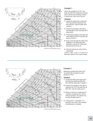
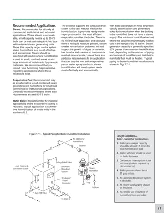
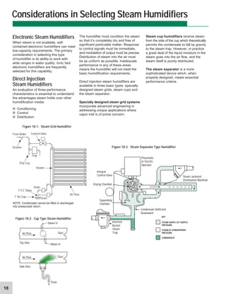
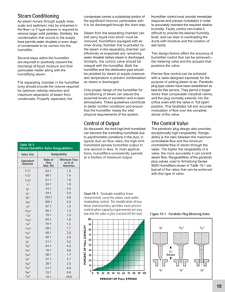
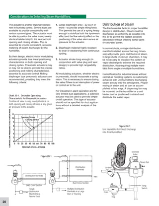
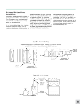
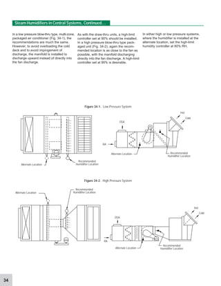
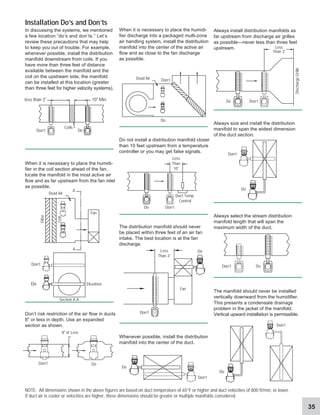
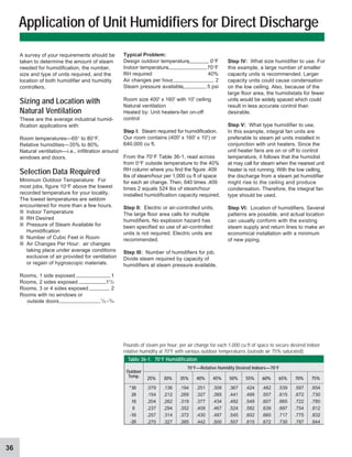
The Armstrong
Humidification
Handbook
Handbook HB-501
2
Although humidity is invisible to our eyes,
we can easily observe its effects. In
human terms, we are more comfortable
and more efficient with proper humid-
ification. In business and industrial environ-
ments, the performance of equipment
and materials is enhanced by effectively
applying humidity control.
Maintaining indoor air quality through
humidity management can lower energy
costs, increase productivity, save labor
and maintenance costs, and ensure
product quality. In short, humidification
can provide a better environment and
improve the quality of life and work.
Armstrong has been sharing know-how
in humidification application since 1938.
Through the design, manufacturing, and
application of humidification equipment
Humidification Plays an Essential Role
Controlled humidification helps protect
humidity-sensitive materials, personnel,
delicate machinery, and equipment.
Beyond the important issues of comfort
and process control, humidity control
can help safeguard against explosive
atmospheres. You can’t afford NOT
to humidify. And the best way to protect
your investment is through proven
humidification strategies and solutions
pioneered by Armstrong.
Armstrong has led the way to countless
savings in energy, time and money.
Armstrong also provides computer
software, video tapes, and other educa-
tional materials to aid in humidification
equipment selection, sizing, installation,
and maintenance.
Armstrong offers the newly updated
Humidification Handbook as a problem-
solving, educational aid for those involved
with the design, installation, and mainten-
ance of environmental control systems
in all types of buildings. In addition, you
may request a free copy of Armstrong’s
Software Program 2 (Humidifier Sizing
and Selection) for step-by-step sizing of
your own installation.
Your specific humidification questions
can be answered by your Armstrong
Representative. Additional support from
Armstrong International humidification
specialists is available to assist with
difficult or unusual problems.
© 1995 Armstrong International, Inc.
3
Why Humidification is Important 4-7
How Humidity Affects Materials 8-9
Determining Humidity Requirements of Materials 10
How Psychrometrics Help in Humidification 11-13
How Humidifiers Work 14-17
Considerations in Selecting Steam Humidifiers 18-21
Basic Application Principles 22-25
Sizing Considerations 26-28
Steam Humidifiers in Central Systems 29-34
Installation Tips 35
Application of Unit Humidifiers for Direct Discharge 36-38
Conclusion 39
Table of Contents
4
Humidity and Temperature
Humidity is water vapor or moisture content
always present in the air. Humidity is
definable as an absolute measure: the
amount of water vapor in a unit of air. But
this measure of humidity does not indicate
how dry or damp the air is. This can only
be done by computing the ratio of the
actual partial vapor pressure to the
saturated partial vapor pressure at
the same temperature. This is relative
humidity, expressed by the formula:
vp
a
= actual vapor pressure
vp
s
= vapor pressure at saturation
t = dry-bulb temperature
For practical purposes, at temperatures
and pressures normally encountered in
building systems, relative humidity is
considered as the amount of water vapor
in the air compared to the amount the air
can hold at a given temperature.
“At a given temperature” is the key to
understanding relative humidity. Warm air
has the capacity to hold more moisture than
cold air. For example, 10,000 cubic feet of
70°F air can hold 80,550 grains of moisture.
The same 10,000 cubic feet of air at 10°F
can hold only 7,760 grains of moisture.
Humidification is simply the addition of
water to air. However, humidity exerts a
powerful influence on environmental and
physiological factors. Improper humidity
levels (either too high or too low) can
cause discomfort for people, and can
damage many kinds of equipment and
materials. Conversely, the proper type of
humidification equipment and controls
can help you achieve effective, economi-
cal, and trouble-free control of humidity.
As we consider the importance of humidity
among other environmental factors—
temperature, cleanliness, air movement,
and thermal radiation—it is important to
remember that humidity is perhaps the
least evident to human perception. Most
of us will recognize and react more quickly
to temperature changes, odors or heavy
dust in the air, drafts, or radiant heat.
Since relative humidity interrelates with
these variables, it becomes a vital
ingredient in total environmental control.
If the 10,000 cubic feet of 10°F air held 5,820
grains of moisture, its relative humidity would
be 75%. If your heating system raises the
temperature of this air to 70°F with no moisture
added, it will still contain 5,820 grains of
Why Humidification is Important
Relative Humidity(RH):
The ratio of the vapor pressure (or
mole fraction) of water vapor in the air
to the vapor pressure (or mole fraction)
of saturated air at the same dry-bulb
temperature and pressure.
Sensible Heat:
Heat that when added to or taken away
from a substance causes a change in
temperature or, in other words, is “sensed”
by a thermometer. Measured in Btu.
Latent Heat:
Heat that when added to or taken away
from a substance causes or accompa-
nies a phase change for that substance.
This heat does not register on a ther-
mometer, hence its name “latent” or
hidden. Measured in Btu.
Dew Point:
The temperature at which condensation
occurs (100%RH) when air is cooled at
a constant pressure without adding or
taking away water vapor.
Evaporative Cooling:
A process in which liquid water is
evaporated into air. The liquid absorbs
the heat necessary for the evaporation
process from the air, thus, there is a
reduction in air temperature and an
increase in the actual water vapor
content of the air.
Enthalpy:
Also called heat content, this is the sum
of the internal energy and the product
of the volume times the pressure.
Measured in Btu/lb.
Hygroscopic Materials:
Materials capable of absorbing or
giving up moisture.
Phase:
The states of existence for a sub-
stance, solid, liquid, or gas (vapor).
moisture. However, at 70°F, 10,000 cubic feet
of air can hold 80,550 grains of moisture. So
the 5,820 grains it actually holds give it a
relative humidity of slightly more than 7%.
That’s very dry...drier than the Sahara Desert.
70°F
80,550 Grains
10°F
7,760 Grains
RH =
vp
a
vp
s
Glossary
t
5
Evaporative Cooling
We’ve discussed the effects of changing
temperature on relative humidity. Altering
RH can also cause temperature to change.
For every pound of moisture evaporated
by the air, the heat of vaporization
reduces the sensible heat in the air by
about 1,000 Btu. This can be moisture
absorbed from people or from wood,
paper, textiles, and other hygroscopic
materials in the building. Conversely, if
hygroscopic materials absorb moisture
from humid air, the heat of vaporization
can be released to the air, raising the
sensible heat.
Dew Point
Condensation will form on windows
whenever the temperature of the glass
surface is below the dew point of the air.
Table 5-2, from data presented in the
ASHRAE Handbook & Product Directory,
indicates combinations of indoor relative
humidity and outside temperature at which
condensation will form. Induction units,
commonly used below windows in modern
buildings to blow heated air across the
glass, permit carrying higher relative
humidities without visible condensation.
Air Movement and Humidity
Another variable, air movement in the
form of infiltration and exfiltration from the
building, influences the relationship between
temperature and relative humidity. Typically,
one to three times every hour (and many
more times with forced air make-up or
exhaust) cold outdoor air replaces your
indoor air. Your heating system heats this
cold, moist outdoor air, producing warm,
dry indoor air.
Per lb
Dry Air
°F
-10
- 5
0
5
10
15
20
25
30
31
32
33
34
35
36
37
38
39
40
41
42
43
44
45
46
47
48
49
Table 5-1. Grains of Water per Cubic Foot of Saturated Air and per Pound of Dry Air
at Various Temperatures. (Abstracted from ASHRAE Handbook)
Per
cu ft
0.28466
0.36917
0.47500
0.609
0.776
0.984
1.242
1.558
1.946
2.033
2.124
2.203
2.288
2.376
2.469
2.563
2.660
2.760
2.863
2.970
3.081
3.196
3.315
3.436
3.562
3.692
3.826
3.964
Per lb
Dry Air
3.2186
4.2210
5.5000
7.12
9.18
11.77
15.01
19.05
24.07
25.21
26.40
27.52
28.66
29.83
31.07
32.33
33.62
34.97
36.36
37.80
39.31
40.88
42.48
44.14
45.87
47.66
49.50
51.42
°F Per
cu ft
Per lb
Dry Air
Per
cu ft
°F Per lb
Dry Air °F Per
cu ft
4.407
4.561
4.722
52
53
54
57.58
59.74
61.99 82
83
84
85
86
11.75
12.11
12.49
12.87
13.27
166.4
172.1
178.0
184.0
190.3
51
50 4.106 53.38
4.255 55.45
5.234
5.415
5.602
6.196
6.407
6.622
7.308
7.571
7.798
8.588
8.867
9.153
57
58
59
62
63
64
67
68
69
72
73
74
69.23
71.82
74.48
83.02
86.03
89.18
99.19
102.8
106.4
118.2
122.4
126.6
77 10.06 140.4
78
79
80
81
9.448
9.749
75
76
131.1
135.7
8.055
8.319
70
71
110.2
114.2
6.845
7.074
65
66
92.40
95.76
5.795
5.993
60
61
77.21
80.08
4.889
5.060
55
56
64.34
66.75
87
94
95
96
104
13.67
16.79
17.28
17.80
22.32
196.7
247.5
255.6
264.0
341.5
105 22.95 352.6
97
98
18.31
18.85
272.7
281.7
99
100
101
102
103
19.39
19.95
20.52
21.11
21.71
290.9
300.5
310.3
320.4
330.8
106 23.60 364.0
93 16.31 239.5
88 14.08 203.3
89
90
91
92
14.51
14.94
15.39
15.84
210.1
217.1
224.4
231.8
10.38
10.71
11.04
11.39
145.3
150.3
155.5
160.9
440.4
454.5
469.0
483.9
566.5
1250.9
1473.5
1743.0
2072.7
2480.8
3664.5
4550.7
5780.6
7581.0
112
113
114
115
120
145
150
155
160
165
175
180
185
190
27.81
28.57
29.34
30.13
34.38
64.04
71.99
80.77
90.43
101.0
125.4
139.2
154.3
170.7
375.8
387.9
400.3
413.3
107 24.26
108
109
110
24.93
25.62
26.34
426.4
111 27.07
662.6
774.9
907.9
1064.7
125
130
135
140
39.13
44.41
50.30
56.81
2996.0
170 112.6
10493.0
15827.0
195
200
188.6
207.9
Double Glass
(Storm Windows
or Thermal Glass)
38%
42%
49%
56%
63%
71%
Single
Glass
11%
16%
21%
28%
37%
48%
Outdoor
Temperature
-10
0
+10
+20
+30
+40
Table 5-2. Relative Humidities at Which
Condensation Will Appear on Windows at
70°F When Glass Surface is Unheated
6
Energy Conservation
With Controlled RH
Indoor relative humidity as we have
computed it is called Theoretical Indoor
Relative Humidity (TIRH). It virtually never
exists. RH observed on a measuring
device known as a hygrometer will almost
always exceed the TIRH. Why? Dry air is
thirsty air. It seeks to draw moisture from
any source it can. Thus it will soak up
moisture from any hygroscopic materials
(such as wood, paper, foodstuffs, leather,
etc.) and dry out the nasal passages and
skin of human beings in the building.
But is this free “humidification”? No, it is
the most expensive kind there is when
translated into terms of human comfort,
material deterioration, and production
difficulties. Moreover, it requires the same
amount of energy whether the moisture
is absorbed from people and materials
or added to the air by an efficient
humidification system.
The true energy required for a humidification
system is calculated from what the actual
humidity level will be in the building, NOT
from the theoretical level. In virtually all
cases, the cost of controlling RH at the
desired level will be nominal in terms of
additional energy load, and in some cases
may result in reduced energy consumption.
A major convention center in the Central
United States reported that it experienced
a decrease in overall steam consumption
when it added steam humidification. From
one heating season with no humidification
to the next with humidifiers operating, the
steam consumption for humidification
was 1,803,000 lbs, while the steam for
heating decreased by 2,486,000 lbs in the
same period. The decreased (metered)
consumption occurred despite 7.2% colder
weather from the previous year. The
records from this installation indicate that it
is possible to reduce the total amount of
steam required for environmental control by
maintaining a higher, controlled relative
humidity.
Let’s examine a theoretical system using
enthalpy (heat content) as our base.
■ Assume a winter day with outside
temperature of 0°F at 75% RH.
■ The enthalpy of the air is .6 Btu/lb dry
air (DA).
■ If the air is heated to 72°F without
adding moisture, the enthalpy becomes
18 Btu/lb DA.
■ Theoretical relative humidity becomes
3.75%, but actual RH will be about 25%.
■ At 72°F and 25% RH the enthalpy is
22 Btu/lb DA.
■ The additional moisture is derived
from hygroscopic materials and
people in the area.
But what about the additional energy—
the difference between the 18 Btu/lb DA
and 22 Btu/lb DA? This 22% increase must
come from the heating system to compen-
sate for the evaporative cooling effect. If a
humidification systemis used and moisture
added to achieve a comfortable 35% RH,
the enthalpy is 23.6 Btu/lb DA.
This is only a 7% increase over the
“inevitable” energy load of 22 Btu/lb DA—
substantially less than the theoretical
increase of 31% from 3.75% RH (18 Btu/lb
DA) to 35% RH (23.6 Btu/lb DA) at 72°F.
If the temperature was only 68°F at 35%
RH (because people can be comfortable
at a lower temperature with higher humidity
levels), the enthalpy is 21.8 Btu/lb DA, or
a slight decrease in energy.
Problems With Dry Air
Dry air can cause a variety of costly,
troublesome, and sometimes dangerous
problems. If you are not familiar with the
effects of dry air, the cause of these
problems may not be obvious. You should
be concerned if you are processing or
handling hygroscopic materials such as
wood, paper, textile fibers, leather, or
chemicals. Dry air and/or fluctuating
humidity can cause serious production
problems and/or material deterioration.
Static electricity can accumulate in dry
atmospheric conditions and interfere with
efficient operation of production machinery
or electronic office machines. Where static-
prone materials such as paper, films,
computer disks, and other plastics are
handled, dry air intensely aggravates the
static problem. In potentially explosive
atmospheres, dry air and its resultant
static electricity accumulations can be
extremely dangerous.
Why Humidification is Important, Continued...
°F °F
INDOOR OUTDOOR
120
100
80
60
40
20
0
20
40
120
100
80
60
40
20
0
20
40
50
40
30
20
10
0
10
20
30
40
°C
7
Humidity and Human Comfort
Studies indicate people are generally most
comfortable when relative humidity is
maintained between 35% and 55%. When
air is dry, moisture evaporates more readily
from the skin, producing a feeling of chilliness
even with temperatures of 75°F or more.
Because human perception of RH is often
sensed as temperature differential, it’s
possible to achieve comfortable conditions
with proper humidity control at lower
temperatures. The savings in heating
costs is typically very significant over the
course of just a single heating season.
The Need for Humidity
Control in Today’s
Electronic Workplace
Electronics are revolutionizing the way
your office and plant floor operates,
communicates, collects data, and main-
tains equipment. In the office, xerographic
copies, phone systems, word processors,
and typewriters, even wall thermostats are
electronically controlled. Personal computers
and CRT access points are sprouting
everywhere. What’s more, office decor
has far more work stations incorporating
wall panels and furniture with natural and
synthetic fabric than ever before.
In manufacturing areas, more machines
are electronically controlled. In fact, you
see more control rooms (just to house
electronic control systems) than in previous
years.
All this means that the nature of today’s
business makes proper humidification a
virtual necessity.
Why Improper Humidification
Threatens Sensitive
Electronic Equipment
Central to all electronic circuits today is
the IC (integrated circuit) or “chip.” The
heart of the IC is a wafer-thin miniature
circuit engraved in semiconductor
material. Electronic components—and
chips in particular—can be overstressed
by electrical transients (voltage spikes).
This may cause cratering and melting of
minute areas of the semiconductor,
leading to operational upsets, loss of
memory, or permanent failure. The
damage may be immediate or the
component may fail sooner than an
identical part not exposed to an electrical
transient.
A major cause of voltage spikes is
electrostatic discharge (ESD). Although
of extremely short duration, transients can
be lethal to the wafer-thin surfaces of
semiconductors. ESD may deliver voltage
as high as lightning, and it strikes faster.
ESD is a particularly dangerous phenom-
enon because you are the source of these
transients. It is the static electricity which
builds up on your body. The jolt you get
from touching a doorknob or shaking
someone’s hand is ESD. Table 7-1 below
shows voltages which can be generated
by everyday activities.
Voltage accumulates on surfaces (in this
case, the human body), and when the
surface approaches another at a lower
voltage a discharge of electrical voltage
occurs. Note the humidity levels at which
these voltages may be generated. As the
level of humidity rises, voltages are
reduced because a film of moisture forms Figure 7-1.
Effect of humidity on electrostatic voltages
Integrated circuit damaged by ESD.
(Photo courtesy of Motorola Semiconductor, Inc.)
on surfaces, conducting the charges to the
ground. Although the 65%-90% RH cited
in Table 7-1 is impractical for office areas,
any increase in humidity will yield a
significant reduction in ESD events.
ESD Damage is Not Only
Possible but Probable
A study of personnel ESD events in a
poorly controlled room with a wool carpet
was conducted for 16 months. The
strength of the ESD event was measured
in current (amps). Results indicate, for
example, that a current discharge of 0.3
amps is 100 times more likely to occur
at 10%-20% RH than at 45%-50% RH.
In other words, the higher the relative
humidity, the lower the occurrence and
severity of ESD.
In addition to the risk of damage to
electronic devices from static electricity
charges, there are grave risks associated
with sparks from static charges in many
process applications. Static electricity is
extremely dangerous in the presence of
gases, volatile liquids, or explosive dusts
such as is found in munitions plants, paint
spray booths, printing plants, pharmaceuti-
cal plants, and other places.
While many static control products
(special mats, carpeting, sprays, straps,
etc.) are available, bear in mind that
humidification is a passive static-control
means. It is working to control static all the
time—not just when someone remembers.
Walking across carpet
Walking over vinyl floor
Worker at bench
Vinyl envelopes for work instructions
Common poly bag picked up from bench
Work chair padded with polyurethane foam
Means of Static
Generatioo
35,000
12,000
6,000
7,000
20,000
18,000
1,500
250
100
600
1,200
1,500
Electrostatic Voltages
10%-20%
Relative Humidity
65%-90%
Relative Humidity
Table 7-1. Effect of Humidity on Electrostatic Voltages
8
Paper and Paper Products
Every production superintendent in the
paper industry is, by experience, familiar
with the excessive scrap losses and
customer complaints that can result from
the following wintertime headaches:
1. Curling of stock.
2. Cracking or breaking at creases of
folding boxes, cartons, corrugated and
solid fiber containers.
3. Loss of package and container
strength.
4. Production delays when sheets fail to
go through machines smoothly due to
static electricity.
5. Gluing failures.
All of the above wintertime problems
have a common cause—dry or curling
paper caused by low indoor relative
humidities.
Whenever you heat air, without adding
moisture, its RH drops. Table 8-1 shows
that 0°F outside air at 75% RH will have a
How Humidity Affects Materials
Why Humidification is Important, Continued...
Figure 9-1. Effects of moisture content in
folding paper. Sheet on left has proper
moisture. Sheet on right lacks enough
moisture—is dry and brittle—breaks on fold.
relative humidity of only 4.4% when heated
to 70°F indoors. Even though the theoreti-
cal RH should be 4.4% in your plant, the
actual observed humidity will be much
higher because of the moisture given off by
the paper. This type of humidification is very
expensive in terms of stock and production.
The RH of surrounding air governs the
moisture content of paper, as shown in
Table 9-1. The fibrils in paper take on
moisture when the paper is drier than the
surrounding air and give up moisture when
the conditions are reversed.
A paper moisture content range of 5%-7%
is essential to maintain satisfactory strength
and workability of paper. This requires an
indoor RH of about 40%-50%, depending
upon the composition of the paper.
Moisture contents of different types of papers
will vary slightly from those shown in the
table but will follow an identical pattern.
Changes in moisture content thus cause
paper to become thicker or thinner, flatter
or curlier, harder or softer, larger or
smaller, limp or brittle.
Effect of Indoor Heating Upon RH and
Moisture Content of Kraft Wrapping Paper.
NOTE: This table assumes an outdoor relative
humidity of 75%. When outdoor RH is less,
as is common, indoor RH will also be less.
Indoor temperatures higher than 70°F will also
cause lower relative humidities.
Indoor Temperature 70°F
Outdoor
Temperature
Degrees
-20
-10
0
10
20
30
40
50
60
70
Indoor
Relative
Humidity %
1.5
2.5
4.4
7.2
11.6
18.1
26.8
38.3
54.0
75.0
Approx.
Moisture
Content of
Paper
0.5
0.8
1.2
2.2
3.3
4.3
5.3
6.4
8.0
11.6
Table 8-1. How Indoor Heating Reduces
Indoor RH and Dries Out Paper
9
Printing
The dry air problems found in paper
manufacturing are equally common to
the printing industry.
Paper curling, generally caused by the
expansion and contraction of an unpro-
tected sheet of paper, takes place when
too dry an atmosphere draws moisture
from the ex-
posed
surface
which
shrinks
and curls.
The curl
will be with
the grain of
the sheet. This
trouble is most pronounced with very
lightweight stocks or with cover stocks,
and coated-one-side papers.
WoodProducts,Woodworking,
and Furniture Manufacture
Like all hygroscopic materials, wood takes
on or gives off moisture as the RH of the
surrounding air varies. When, at any given
temperature and relative humidity, the
wood finally stops absorbing or liberating
moisture, it is said to have
reached its equilibrium
moisture content (EMC).
The moisture in the
wood is then “in balance”
with the moisture in the air.
It is generally not practical to hold
indoor RH as high during the cold months
as it is during the warm months. However,
when the cold season sets in, humidifiers
permit a gradual reduction of RH and
EMC to a practical minimum working level.
Under this controlled condition, warping
and cracking will not occur.
Leather Processing
RH maintained uniformly in the 40%-60%
range (higher in muller rooms) reduces
cracking, minimizes loss of pliability, helps
maintain quality and appearance, and
reduces the dust problem in the plant.
Offices
RH maintained at 30%-40% stops
splitting, checking, shrinkage, and glue
joint failure in paneling and furnishings,
adds life to carpeting and draperies.
Electronic office equipment such as
computers, xerographic copiers, and
phone systems require a constant RH
of 40%-50% to guard against harmful
electrical transients (see page 7).
Libraries and Museums
Relative humidity maintained uniformly at
40%-55% in storage rooms, vaults, and
galleries prolongs the life of valuable
collections by stabilizing the pliability of
glue, starch and casein. The embrittle-
ment of fibers in paper, canvas, papyrus,
leather bindings, etc., is minimized.
Relative Humidity %
Material Description
10 20 30 40 50 60 70 80 90
M.F. Newsprint Wood Pulp 24% Ash 2.1 3.2 4.0 4.7 5.3 6.1 7.2 8.7 10.6
HMF Writing Wood Pulp 3% Ash 3.0 4.2 5.2 6.2 7.2 8.3 9.9 11.9 14.2
White Bond Rag 1% Ash 2.4 3.7 4.7 5.5 6.5 7.5 8.8 10.8 13.2
Com. Ledger 75% Rag 1% Ash 3.2 4.2 5.0 5.6 6.2 6.9 8.1 10.3 13.9
Kraft Wrapping Coniferous 3.2 4.6 5.7 6.6 7.6 8.9 10.5 12.6 14.9
Table 9-1. Moisture Content of Paper at Various Relative Humidities
10
moisture loss and materials deterioration
and/or production problems that result.
vary greatly from one material to the next.
We will discuss typical hygroscopic materials
which require specific RH levels to avoid
Determining Humidity Requirements of Materials
No single level of relative humidity provides
adequate moisture content in all hygroscopic
materials. Moisture content requirements
Table 10-1. Recommended Relative Humidities
Abstracted from the ASHRAE Handbook Systems and Applications
Tea
Packaging 65 65
Tobacco
Cigar & cigarette making 70-75 55-65
Softening 90 85-88
Stemming & stripping 75-85 70-75
Packing & shipping 73-75 65
Filler tobacco casing
& conditioning 75 75
Filter tobacco storage
& preparation 77 70
Wrapper tobacco storage
& conditioning 75 75
Pharmaceuticals
Powder storage (prior to mfg)* *
Manufactured powder storage
& packing areas 75 35
Milling room 75 35
Tablet compressing 75 35
Tablet coating room 75 35
Effervescent tablets & powders75 20
Hypodermic tablets 75 30
Colloids 75 30-50
Cough drops 75 40
Glandular products 75 5-10
Ampoule manufacturing 75 35-50
Gelatin capsules 75 35
Capsule storage 75 35
Microanalysis 75 50
Biological manufacturing 75 35
Liver extracts 75 35
Serums 75 50
Animal rooms 75-80 50
Small animal rooms 75-78 50
* Store in sealed plastic containers in sealed drums.
Photographic Processing
Photo Studio
Dressing room 72-74 40-50
Studio (camera room) 72-74 40-50
Film darkroom 70-72 45-55
Print darkroom 70-72 45-55
Drying room 90-100 35-45
Finishing room 72-75 40-55
Storage room
b/w film & paper 72-75 40-60
color film & paper 40-50 40-50
Motion picture studio 72 40-55
Static Electricity Control
Textiles, paper, explosive control > 55
Clean Rooms & Spaces 45
Data Processing 72 45-50
Paper Processing
Finishing area 70-75 40-45
Test laboratory 73 50
Switchgear:
Fuse & cutout assembly 73 50
Capacitor winding 73 50
Paper storage 73 50
Conductor wrapping with yarn75 65-70
Lightning arrester assembly 68 20-40
Thermal circuit breakers
assembly & test 75 30-60
High-voltage transformer repair79 55
Water wheel generators:
Thrust runner lapping 70 30-50
Rectifiers:
Processing selenium &
copper oxide plates 73 30-40
Fur
Storage 40-50 55-65
Gum
Manufacturing 77 33
Rolling 68 63
Stripping 72 53
Breaking 73 47
Wrapping 73 58
Leather
Drying 68-125 75
Storage, winter room temp. 50-60 40-60
Lenses (Optical)
Fusing 75 45
Grinding 80 80
Matches
Manufacture 72-73 50
Drying 70-75 60
Storage 60-63 50
Mushrooms
Spawn added 60-72 nearly sat.
Growing period 50-60 80
Storage 32-35 80-85
Paint Application
Oils, paints: Paint spraying 60-90 80
Plastics
Manufacturing areas:
Thermosetting molding
compounds 80 25-30
Cellophane wrapping 75-80 45-65
Plywood
Hot pressing (resin) 90 60
Cold pressing 90 15-25
Rubber-Dipped Goods
Cementing 80 25-30*
Dipping surgical articles 75-80 25-30*
Storage prior to manufacture60-75 40-50*
Laboratory (ASTM Standard) 73.4 50*
* Dew point of air must be below evaporation
temperature of solvent
Residences 70-72 30
Libraries & Museums
Archival 55-65 35
Art storage 60-72 50
Stuffed fur animals 40-50 50
Communication Centers
Telephone terminals 72-78 40-50
Radio & TV studios 74-78 30-40
General Commercial & Public Buildings
70-74 20-30
(including cafeterias, restaurants, airport terminals,
office buildings, & bowling centers)
Hospitals & Health Facilities
General clinical areas 72 30-60
Surgical area
Operating rooms 68-76 50-60
Recovery rooms 75 50-60
Obstetrical
Full-term nursery 75 30-60
Special care nursery 75-80 30-60
Industrial Hygroscopic Materials
Abrasive
Manufacture 79 50
Ceramics
Refractory 110-150 50-90
Molding room 80 60-70
Clay storage 60-80 35-65
Decalcomania production 75-80 48
Decorating room 75-80 48
Cereal
Packaging 75-80 45-50
Distilling
Storage
Grain 6 35-40
Liquid yeast 32-33
General manufacturing 60-75 45-60
Aging 65-72 50-60
Electrical Products
Electronics & X-ray:
Coil & transformer winding72 15
Semi conductor
assembly 68 40-50
Electrical instruments:
Manufacture
& laboratory 70 50-55
Thermostat assembly
& calibration 75 50-55
Humidistat assembly
& calibration 75 50-55
Small mechanisms:
Close tolerance assembly72 40-45
Meter assembly & test 75 60-63
PROCESS OR PRODUCT Temp.°F %RH PROCESS OR PRODUCT Temp.°F %RH
PROCESS OR PRODUCT Temp.°F %RH
11
How Psychrometrics Help in Humidification
Psychrometrics is the measurement of
thermodynamic properties in moist air.
As a problem-solving tool psychrometrics
excel in clearly showing how changes in
heating, cooling, humidification, and
dehumidification can affect the properties
of moist air. Psychrometric data is needed
to solve various problems and processes
relating to air distribution.
Most complex problems relating to heating,
cooling and humidification are combina-
tions of relatively simple problems. The
psychrometric chart illustrates these pro-
cesses in graphic form, clearly showing how
changes affect the properties of moist air.
One of the reasons psychrometric data is
particularly important today is traceable to
the way most new buildings (and many
older ones) are heated. The lower duct
temperatures (55°F and below) used in
new buildings make accurate humidity
control more difficult to achieve. (This is
because low duct temperatures have a
limited ability to absorb moisture. Adding
moisture via the central air handling
system must compensate for reheating
of air before it leaves the duct.)
For such applications, booster humid-
ification must sometimes be accomplished
in the duct of the zone after it has reached
its final temperature (reheated).
To maintain typical conditions of 70°F and
50% RH, duct humidities will be very high
(75% RH and above). To keep the duct
from becoming saturated, a duct high limit
humidistat is used, and becomes in these
cases the main controller of the humidifier.
Since this humidistat is in close proximity
to the humidifier, and air is constantly
moving, and must be controlled close to
saturation, the humidifier output control
must be fast, accurate and repeatable.
TOTAL HEAT
∆H T
SENSIBL E H E A T
∆H s
ENTHALPY
∆h
HUMIDITY RATIO
∆W
5
0
0
0
-
1
0
0
0
~
2
0
0
0
–
5
0
0
0
3
0
0
0
2
0
0
0
1500
1.0
0.8
0.6
0.5
0.4
0
.
3
0
.
2
0
.1
1.0
2.0
4.0
8.0
-8.0
-4.0
-2.0
-1.0
-
0
.
5
-
0
.
4
-
0
.
3
-
0
.
2
-0
.1
60
50
4
0
3
0
20
1
0
0
1
2
0
1
1
0
100
9
0
80
70
20
15
10
5
0
5
10
15
25
3
0
35
40
45
°C
°F
5
2
9
5
3
1
5
30
1
0
2
0
10
10
990
9
8
0
970
960
9
5
0
1030
10
40
MILLIBARS
INCHES
60
50
4
0
3
0
2
0
1
0
0
9
0
8
0
7
0
55
45
35
25
15
65
75
85
95
HUMIDITY
%
RELATIVE HUMIDTY
2
8
1
0
BAROMETER
1000
THERMOMETER
SATU
R
ATIO
N
TEM
PER
ATU
R
E
F
1
2
.
5
1
3
.
0
1
3
.
5
1
4
.
0
1
4
.
5
V
O
L
U
M
E
C
U
.
F
T
.
P
E
R
L
B
.
D
R
Y
A
I
R
1
5
.
0
9
0
%
8
0
%
7
0
%
6
0
%
50%
40%
30%
20
10 RELATIVE HUMIDITY
120
115
110
105
100
DRY
BULB
TEMPERATURE
—
F
95
90
85
80
75
70
65
60
55
50
45
40
35
65
60
55
50
45
40
35
30
25
70
75
80 WET BULB TEMPERATURE
85
90
35
40
45
50
55
60
65
70
75
80
85
15
15 20 25
30
35
40
45
50
55
60
60
55
10
20
25
30
35
40
45
50
EN
TH
ALPY
(h) BTU
PER
BO
U
N
D
O
F
D
RY
AIR
ENTHALPY (h) BTU PER BOUND OF DRY AIR
.028
.026
.024
.022
.020
.018
.016
.014
.012
.010
.008
.006
.004
.002
HUMIDITY
RATIO
(W)
—
POUNDS
MOISTURE
PER
POUND
DRY
AIR
12
The psychrometric chart is a graphical
representation of the thermodynamic
properties which impact moist air.
It consists of eight major components:
Using the Psychrometric Chart
1. Humidity ratio values are plotted
vertically along the right-hand margin,
beginning with 0 at the bottom and
extending to .03 at the top.
2. Enthalpy, or total heat, is plotted with
oblique lines, at intervals of 5 Btu/lb of dry
air, extending from upper left to lower right.
3. Dry-bulb temperature lines are
plotted vertically at 1°F intervals.
4. Wet-bulb temperature lines are
indicated obliquely and fall almost parallel
to enthalpy lines. They are shown at 1°F
intervals.
5. Relative humidity lines curve across
the chart from left to right at intervals of
10%. They begin at the bottom at 10%
and end at the top with the saturation curve
(100%).
7. Two-phase region includes a narrow,
cross-hatched area to the left of the
saturation region indicating a mixture of
condensed water in equilibrium.
6. Volume lines indicating cubic feet per
pound of dry air are plotted at intervals
of .5 cubic foot.
8. The protractor at the upper left of the
chart contains two scales. One is for the
ratio of enthalpy difference. The other is
for a ratio of sensible heat to the total
heat. The protractor establishes the angle
of a line on the chart along which a
process will follow.
How Psychrometrics Help in Humidification, Continued...
0.030
0.028
0.026
0.024
0.022
0.020
0.018
0.016
0.014
0.012
0.010
0.008
0.006
0.004
0.002
0
HUMIDITY
RATIO,
POUNDS
MOISTURE
PER
POUND
DRY
AIR
10
15
20
25
30
35
40
45
50
55
ENTHALPY
(H) BTU
per pound
of dry air
35 40 45 50 55 60 65 70 75 80 85 90 95 100 105 110 115 120
25 30 35 40
45
50
55
60
65
70
75
80
85
90
9
0
%
8
0
%
7
0
%
6
0
%
50%
40%
30%
20%
10%
1
0
0
%
1
4
.
5
V
o
l
u
m
e
(
c
u
b
i
c
f
e
e
t
p
e
r
p
o
u
n
d
o
f
d
r
y
a
i
r
)
1
5
.
0
1
4
.
0
1
3
.
0
1
3
.
5
1
2
.
5
Saturation
Tem
perature
°F
TOTAL HEAT
∆H T
SENSIBL E H E A T
∆H s
ENTHALPY
∆h
HUMIDITY RATIO
∆W
5
0
0
0
-
1
0
0
0
~
2
0
0
0
–
5
0
0
0
3
0
0
0
2
0
0
0
1500
1.0
0.8
0.6
0.5
0.4
0
.
3
0
.
2
0
.1
1.0
2.0
4.0
8.0
-8.0
-4.0
-2.0
-1.0
-
0
.
5
-
0
.
4
-
0
.
3
-
0
.
2
-0
.1
13
SATU
R
ATIO
N
TEM
PER
ATU
R
E
F
1
2
.5
1
3
.0
1
3
.5
1
4
.0
1
4
.
5
V
O
L
U
M
E
C
U
.
F
T
.
P
E
R
L
B
.
D
R
Y
A
I
R
1
5
.0
9
0
%
8
0
%
7
0
%
6
0
%
50%
40%
30%
20
10 RELATIVE HUMIDITY
120
115
110
105
100
DRY
BULB
TEMPERATURE
—
F
95
90
85
80
75
70
65
60
55
50
45
40
35
65
60
55
50
45
40
35
30
25
70
75
80 WET BULB TEMPERATURE
85
90
35
40
45
50
55
60
65
70
75
80
85
15
15 20 25
30
35
40
45
50
55
60
60
55
10
20
25
30
35
40
45
50
EN
TH
ALPY
(h) BTU
PER
BO
U
N
D
O
F
D
RY
AIR
ENTHALPY (h) BTU PER BOUND OF DRY AIR
.028
.026
.024
.022
.020
.018
.016
.014
.012
.010
.008
.006
.004
.002
HUMIDITY
RATIO
(W)
—
POUNDS
MOISTURE
PER
POUND
DRY
AIR
TOTAL HEAT
∆H T
SENSIBL E H E A T
∆H s
ENTHALPY
∆h
HUMIDITY RATIO
∆W
5
0
0
0
-
1
0
0
0
~
2
0
0
0
–
5
0
0
0
3
0
0
0
2
0
0
0
1500
1.0
0.8
0.6
0.5
0.4
0
.
3
0
.
2
0.
1
1.0
2.0
4.0
8.0
-8.0
-4.0
-2.0
-1.0
-
0
.
5
-
0
.
4
-
0
.
3
-0
.2
-0
.1
Example 1
Given the conditions of 75°F dry
bulb and 50% RH, determine the dew
point, volume and humidity content
in grains per cubic foot of dry air.
Solution:
1. Locate the state point, where the
75°F dry-bulb line intersects the
50% RH line. Call this state point
number 1.
2. Project horizontally to the left to
the saturation curve and read 55°F
(dew point).
3. Project horizontally to the right and
read .0092 pounds of moisture per
pound of dry air.
4. Draw a line through the state point
parallel to 13.5 volume line and
estimate a volume of 13.68 cubic
feet per pound of dry air.
5. Solve for grains per cubic foot by
converting:
0.0092 x 7,000 ÷ 13.68 = 4.71 grains/cu ft
See also Table 27-5 for quick values.
Example 2
Determine resultant RH when 55°F
air at 80% RH is heated to a tem-
perature of 75°F.
Solution:
1. Locate the state point where 55°F
dry-bulb line intersects 80% RH
line. Call this state point number 2.
2. Project horizontally to the right to
intersect the 75°F dry-bulb line at
40% RH. Call this state point 3.
3. Observe that if air is delivered to
a system at state point 2, that a
reheat operation can deliver it to
an area at state point 3.
4. If state point 1 (example 1) is
desired in the area, then booster
humidification is needed.
TOTAL HEAT
∆H T
SENSIBL E H E A T
∆H s
ENTHALPY
∆h
HUMIDITY RATIO
∆W
5
0
0
0
-
1
0
0
0
~
2
0
0
0
–
5
0
0
0
3
0
0
0
2
0
0
0
1500
1.0
0.8
0.6
0.5
0.4
0
.
3
0
.
2
0.
1
1.0
2.0
4.0
8.0
-8.0
-4.0
-2.0
-1.0
-
0
.
5
-
0
.
4
-
0
.
3
-0
.2
-0
.1
No. 3
No. 2
No. 1
14
Steam Humidification
Unlike other humidification methods,
steam humidifiers have a minimal effect
on dry-bulb (DB) temperatures. The steam
humidifier discharges ready-made water
vapor. This water vapor does not require
any additional heat as it mixes with the air
and increases relative humidity. Steam is
pure water vapor existing at 212°F (100°C).
This high temperature creates a percep-
tion that steam, when discharged into the
air, will actually increase air temperature.
This is a common misconception. In truth,
as the humidifier discharges steam into
the air, a steam/air mixture is established.
In this mixture steam temperature will
rapidly decrease to essentially the air
temperature.
How Humidifiers Work
Direct Steam Injection
Humidifiers
The most common form of steam
humidifier is the direct steam injection
type. From a maintenance point of view,
direct steam humidification systems
require very little upkeep. The steam
supply itself acts as a cleaning agent to
keep system components free of mineral
deposits that can clog water spray and
evaporative pan systems.
Response to control and pinpoint control
of output are two other advantages of the
direct steam humidification method. Since
steam is ready-made water vapor, it needs
only to be mixed with air to satisfy the
demands of the system. In addition, direct
steam humidifiers can meter output by
means of a modulating control valve. As
the system responds to control, it can
position the valve anywhere from closed
to fully open. As a result, direct steam
humidifiers can respond more quickly and
precisely to fluctuating demand.
The high temperatures inherent in steam
humidification make it virtually a sterile
medium. Assuming boiler makeup water
is of satisfactory quality and there is no
condensation, dripping or spitting in the
ducts, no bacteria or odors will be
disseminated with steam humidification.
Corrosion is rarely a concern with a
properly installed steam system. Scale
and sediment—whether formed in the unit
or entrained in the supply steam—are
drained from the humidifier through the
steam trap.
Steam-to-Steam Humidifiers
Steam-to-steam humidifiers use a heat
exchanger and the heat of treated steam to
create a secondary steam for humidification
from untreated water. The secondary
steam is typically at atmospheric pressure,
placing increased importance on
equipment location.
Maintenance of steam-to-steam humidifiers
is dependent on water quality. Impurities
such as calcium, magnesium and iron
can deposit as scale, requiring frequent
cleaning. Response to control is slower
than with direct steam because of the
time required to boil the water.
Electronic Steam Humidifiers
(Electrode)
Electronic steam humidifiers are used
when a source of steam is not available.
Electricity and water create steam at
atmospheric pressure. Electrode-type units
pass electrical current through water to
provide proportional output. Use with pure
demineralized, deionized or distilled water
alone will generally not provide sufficient
conductivity for electrode units.
Water quality affects the operation and
maintenance of electrode-type humidifiers.
Use with hard water requires more frequent
cleaning, and pure softened water can
shorten electrode life. Microprocessor-
based diagnostics assist with
troubleshooting.
The psychrometric chart helps illustrate
that steam humidification is a constant DB
process. Starting from a point on any DB
temperature line, steam humidification will
cause movement straight up along the
constant DB line. The example illustrates
that 70°F DB is constant as we increase
RH from 30%-50%. This is true because
steam contains the necessary heat
(enthalpy) to add moisture without
increasing or decreasing DB
temperature. Actual results
utilizing high pressure steam
or large RH increases
(more than 50%) increase
DB by 1° to 2°F. As a result,
no additional heating or air
conditioning load occurs.
70° DB
50%
30%
Cross Section of Manifold
Dry Steam
Direct Steam Humidification
Figure 14-1.
Steam-to-Steam Humidification
Figure 14-2.
15
Electrode units are easily adaptable to
different control signals and offer full
modulated output. However, the need to
boil the water means control will not
compare with direct-injection units.
Electronic Steam Humidifiers
(Ionic Bed)
Ionic bed electronic humidifiers typically
use immersed resistance heating elements
to boil water. Since current does not pass
through water, conductivity is not a
concern. Therefore, ionic bed technology
makes the humidifier versatile enough to
accommodate various water qualities.
These units work by using ionic bed
cartridges containing a fibrous media to
attract solids from water as its temperature
rises, minimizing the buildup of solids
inside the humidifier. Water quality does
not affect operation, and maintenance
typically consists of simply replacing the
cartridges.
Ionic bed humidifiers are adaptable to
different control signals and offer full
modulated output. Control is affected by
the need to boil the water, however.
Water Spray
The water spray process can create
potential temperature control problems. In
order to become water vapor or humidity,
water requires approximately 1,000 Btu
per pound to vaporize. This heat must be
drawn from the air, where it will hopefully
vaporize. If not enough heat is available
quickly enough, the water remains a
liquid. This unvaporized water can result in
overhumidification, and the water can
“plate out” on surfaces, creating a sanita-
tion hazard.
Water spray contains virtually none of the
heat of vaporization required to increase
the RH of the air to desired conditions.
For this reason, water spray humidification
is a virtually constant enthalpy process.
However, as the psychrometric example
illustrates, DB temperature changes as we
increase RH from 30%-50%. The result of
this loss of DB temperature is an in-
creased heating load to maintain 70°F.
Water Spray
Figure 15-2.
70° DB
50%
30%
ENTHALPY
70° DB
50%
30%
Heat Taken From Air
To Evaporate Moisture
Water Supply
Under Pressure
Water Mist
Response of water spray humidifiers
to control is slow due to the need for
evaporation to take place before humidi-
fied air can be circulated. On/off control
of output means imprecise response to
system demand and continual danger
of saturation. Water spray systems can
distribute large amounts of bacteria, and
unevaporated water discharge can
collect in ducts, around drains and drip
pans, and on eliminator plates, encour-
aging the growth of algae and bacteria.
Corrosion is another ongoing problem
with water spray humidification. Scale
and sediment can collect on nozzles,
ductwork, eliminator plates, etc., leading
to corrosion and high maintenance costs.
Evaporative Pan
The evaporative pan method uses steam,
hot water or electricity to provide energy
for heating coils which in turn heat water
and create water vapor. This method is
most effective when installed in smaller
capacity environments either in the air
handling system or individually within
the area(s) to be humidified.
Evaporative pan humidification can
increase dry-bulb temperature as mea-
sured on the psychrometric chart. This
unwanted temperature change may occur
as air is forced across the warmed water
in the pan. The increase in DB can cause
damaging results in process applications
and increase the need for humidity control.
The psychrometric chart helps illustrate
that evaporative pan humidification is not
a constant DB process. This example
shows DB temperature increasing as we
move from 30%-50% RH. To maintain a
constant DB of 70°F some cooling load
(air conditioning) is required.
Figure 15-1.
Electronic Steam Humidification
16
HowHumidifiersWork,Continued...
Cost Comparisons
To fairly evaluate the costs of selecting a
humidification system, you should include
installation, operating, and maintenance
costs as well as initial costs. Total humidi-
fication costs are typically far less than
heating or cooling system costs.
Initial costs, of course, vary with the size
of the units. Priced on a capacity basis,
larger capacity units are the most
economical, regardless of the type of
humidifier, i.e.: one humidifier capable of
delivering 1,000 pounds of humidification
per hour costs less than two 500 lbs/hr
units of the same type.
Direct steam humidifiers will provide the
highest capacity per first cost dollar; water
spray and evaporative pan are the least
economical, assuming capacity needs of
75 lbs/hr or more.
Installation costs for the various types
cannot be accurately formulated because
the proximity of water, steam and electricity
to humidifiers varies greatly among
installations. Operating costs are low for
direct steam and slightly higher for steam-
to-steam. Water spray and evaporative pan
operating costs are also low. Energy costs
are higher for electronic humidifiers.
Direct steam humidifiers have the lowest
maintenance costs. Ionic bed electronic
humidifiers are designed specifically to
minimize maintenance while adapting to
various water qualities. Maintenance costs
for other types can vary widely, depending
on water quality and applications.
These are the principal considerations in
selecting a humidification system. Table
16-1 summarizes the capabilities of each
humidifier type.
Heated Water
Water Pan
Water Vapor
Float
Valve Steam, Hot Water
Or Electricity In
Auto Valve
Evaporative Pan
Figure 16-1.
Maintenance of evaporative pan humid-
ification systems demands regular
cleaning of the heating coils and pan,
which are subject to “liming up.”
The use of chemical additives added
either automatically or manually to the
water in the pan can reduce this problem
by as much as half.
Response to control with the evaporative
pan method is slow due to the time
required for evaporation to take place
before humidified air can be circulated.
Output is determined by water tempera-
ture and surface area.
Evaporative pan humidifiers can sustain
bacteria colonies in the reservoir and
distribute them throughout the humidified
space. High water temperatures, water
treatment, and regular cleaning and
flushing of the humidifier help to minimize
the problem, however.
Table 16-1. Comparison of Humidification Methods
Maintenance frequency
Subject to severe
corrosion and
bacteria problems
Pan subject to
corrosion; bacteria
can be present
Effect on temperature
Unit capacity per unit size
Vapor quality
Response to control
Control of output
Sanitation/corrosion
Installation
Operating
Maintenance
Evaporative Pan Water Spray
Small
temperature rise
Substantial
temperature drop
Small Small
Poor
Slow Slow
Weekly to monthly
High
Low
Direct Steam
Small to very large
Excellent
Immediate
Good to excellent
Sterile medium;
corrosion free
Annual
Low
Low
Maintenance difficulty
Costs: Price
(per unit of capacity)
Low
High
Steam-to-Steam
Virtually no change
Small
Good
Slow
Below average
Bacteria can
be present
Monthly
High
Low
High
Medium
Electronic Steam
Small to medium
Good
Fair
Average
Programmed to not
promote bacteria
Monthly to quarterly
High
Medium
Varies with availability of steam, water, electricity, etc.
Medium
Low
Ionic Bed Electronic Steam
Small to medium
Good
Fair
Average
Programmed to not
promote bacteria
Quarterly to semi-annually
Low to medium
Medium
Medium
Good
Average
High
Low
High
Average
Weekly to bimonthly
High
Medium to high
Low
Very high
17
Recommended Applications
Steam: Recommended for virtually all
commercial, institutional and industrial
applications. Where steam is not avail-
able, small capacity needs up to 50-75
lbs/hr can be met best using ionic bed type
self-contained steam generating units.
Above this capacity range, central system
steam humidifiers are most effective
and economical. Steam should be
specified with caution where humidification
is used in small, confined areas to add
large amounts of moisture to hygroscopic
materials. We recommend that you
consult your Armstrong Representative
regarding applications where these
conditions exist.
Evaporative Pan: Recommended only
as an alternative to self-contained steam
generating unit humidifiers for small load
commercial or institutional applications.
Generally not recommended where load
requirements exceed 50-75 lbs/hr.
Water Spray: Recommended for industrial
applications where evaporative cooling is
required; typical application is summer-
time humidification of textile mills in the
southern U.S.
The evidence supports the conclusion that
steam is the best natural medium for
humidification. It provides ready-made
vapor produced in the most efficient
evaporator possible, the boiler. There is
no mineral dust deposited, and because
there is no liquid moisture present, steam
creates no sanitation problems, will not
support the growth of algae or bacteria,
has no odor and creates no corrosion or
residual mineral scale. Unless there are
particular requirements to an application
that can only be met with evaporative
pan or water spray methods, steam
humidification will meet system needs
most effectively and economically.
Strainer
Safety Relief Valve
“Packaged”
Steam
Generator
Automatic
Blowdown
System
Trap
To Drain
To Additional
Humidifiers
Steam
Humidifier
To Drain
Auto Fill Valve
Figure 17-1. Typical Piping for Boiler-Humidifier Installation
Design Guidelines—
Boiler-Humidifier Combinations
1. Boiler gross output capacity
should be at least 1.5 times the
total humidification load.
2. Water softeners should be used
on boiler feedwater.
3. Condensate return system is not
necessary (unless required by
circumstances).
4. Boiler pressure should be at
15 psig or less.
5. An automatic blowdown system
is desirable.
6. All steam supply piping should
be insulated.
7. No limit to size or number of
humidifiers from one boiler.
With these advantages in mind, engineers
specify steam boilers and generators
solely for humidification when the building
to be humidified does not have a steam
supply. The minimum humidification load
where this becomes economically feasible
falls in the range of 50-75 lbs/hr. Steam
generator capacity is generally specified
50% greater than maximum humidification
load, depending on the amount of piping
and number of humidifiers and distribution
manifolds that must be heated. Typical
piping for boiler-humidifier installations is
shown in Fig. 17-1.
Level Control &
Low Water Cutoff
18
Considerations in Selecting Steam Humidifiers
Electronic Steam Humidifiers
When steam is not available, self-
contained electronic humidifiers can meet
low-capacity requirements. The primary
consideration in selecting this type
of humidifier is its ability to work with
wide ranges in water quality. Ionic bed
electronic humidifiers are frequently
selected for this capability.
Direct Injection
Steam Humidifiers
An evaluation of three performance
characteristics is essential to understand
the advantages steam holds over other
humidification media:
■ Conditioning
■ Control
■ Distribution
The humidifier must condition the steam
so that it’s completely dry and free of
significant particulate matter. Response
to control signals must be immediate,
and modulation of output must be precise.
Distribution of steam into the air must
be as uniform as possible. Inadequate
performance in any of these areas
means the humidifier will not meet the
basic humidification requirements.
Direct injection steam humidifiers are
available in three basic types: specially
designed steam grids, steam cups and
the steam separator.
Specially designed steam grid systems
incorporate advanced engineering in
addressing unique applications where
vapor trail is of prime concern.
Steam cup humidifiers receive steam
from the side of the cup which theoretically
permits the condensate to fall by gravity
to the steam trap. However, in practice
a great deal of the liquid moisture in the
steam goes into the air flow, and the
steam itself is poorly distributed.
The steam separator is a more
sophisticated device which, when
properly designed, meets essential
performance criteria.
Figure 18-3. Steam Separator Type Humidifier
,
,
,
,
,


Integral
Control Valve
Drying Chamber
Separating
Chamber
Inverted
Bucket
Steam
Trap
Condensate Deflected
Downward
Steam Jacketed
Distribution Manifold
Pneumatic
or Electric
Operator


STEAM SUPPLY AT SUPPLY
PRESSURE
STEAM AT ATMOSPHERIC
PRESSURE
CONDENSATE
KEY
Drain
Drain
Strainer
Trap
NOTE: Condensate cannot be lifted or discharged
into pressurized return.
From Boiler
Figure 18-1. Steam Grid Humidifier
Figure 18-2. Cup Type Steam Humidifier
Drip Leg
1/12 Slope
1 Air Gap
Header
Air Flow
Control Valve
19
Figure 19-1. Parabolic Plug Metering Valve
Steam Conditioning
As steam moves through supply lines,
scale and sediment may be entrained in
the flow—a Y-type strainer is required to
remove larger solid particles. Similarly, the
condensation that occurs in the supply
lines permits water droplets or even slugs
of condensate to be carried into the
humidifier.
Several steps within the humidifier
are required to positively prevent the
discharge of liquid moisture and finer
particulate matter along with the
humidifying steam.
The separating chamber in the humidifier
body should provide the volume required
for optimum velocity reduction and
maximum separation of steam from
condensate. Properly separated, the
Chart 19-1. Desirable modified linear
characteristic curve for valves used under
modulating control. The modification of true
linear characteristics provides more precise
control when capacity requirements are very
low and the valve is just cracked off the seat.
7/32
9/32
5/16
11/32
3/8
13/32
15/32
1/2
9/16
5/8
3/4
7/8
Equivalent
Diameter
Rangeability
Ratio of
Flow
Max: Mii
Minimum Flow
as % of
Maximuu
Valve Size
1
1
1
1
63:1
69:1
61:1
53:1
44:1
33:1
123:1
105:1
97:1
85:1
75:1
64:1
70:1
59:1
49:1
40:1
31:1
24:1
18:1
59:1
37:1
28:1
21:1
15:1
10:1
1.6
1.4
1.6
1.9
2.3
3.0
0.8
0.9
1.0
1.2
1.3
1.6
1.4
1.7
2.0
2.5
3.2
4.2
5.6
1.7
2.7
3.5
4.8
6.9
10.0
Table 19-1.
Steam Humidifier Valve Rangeabilities
1/2
1/4
1/8
7/16
1/4
3/16
5/32
1/8
7/64
3/32
5/64
1/16
Humidifier control must provide immediate
response and precise modulation in order
to accurately maintain the required relative
humidity. Faulty control can make it
difficult to provide the desired humidity
level, and can lead to overloading the
ducts with moisture and the creation of
wet spots.
Two design factors affect the accuracy of
humidifier control that can be achieved—
the metering valve and the actuator that
positions the valve.
Precise flow control can be achieved
with a valve designed expressly for the
purpose of adding steam to air. Parabolic
plug type valves have been established as
best for this service. They permit a longer
stroke than comparable industrial valves,
and the plug normally extends into the
orifice even with the valve in “full open”
position. This facilitates full and accurate
modulation of flow over the complete
stroke of the valve.
The Control Valve
The parabolic plug design also provides
exceptionally high rangeability. Range-
ability is the ratio between the maximum
controllable flow and the minimum
controllable flow of steam through the
valve. The higher the rangeability of a
valve, the more accurately it can control
steam flow. Rangeabilities of the parabolic
plug valves used in Armstrong Series
9000 Humidifiers shown in Table 19-1 are
typical of the ratios that can be achieved
with this type of valve.
condensate carries a substantial portion of
the significant micronic particulates with
it to be discharged through the drain trap.
Steam from the separating chamber can
still carry liquid mist which must be
removed. Humidifiers equipped with an
inner drying chamber that is jacketed by
the steam in the separating chamber can
effectively re-evaporate any remaining
water droplets before steam is discharged.
Similarly, the control valve should be
integral with the humidifier. Both the
humidifier and the distribution pipe should
be jacketed by steam at supply pressure
and temperature to prevent condensation
as steam is discharged.
Only proper design of the humidifier for
conditioning of steam can assure the
essential levels of sanitation and a clean
atmosphere. These guidelines contribute
to better comfort conditions and ensure
that the humidifier meets the vital
physical requirements of the system.
Control of Output
As discussed, the duct high-limit humidistat
can become the controlling humidistat due
to psychrometric conditions in the duct. In
typical duct air flow rates, the high limit
humidistat senses humidifier output in
one second or less. In most applica-
tions, humidifiers consistently operate
at a fraction of maximum output.
100
90
80
70
60
50
40
30
20
10
0
0 10 20 30 40 50 60 70 80 90 100
PERCENT OF FULL STROKE
PERCENT
OF
FULL
CAPACITY
3/4
Stroke
3/8
3/8 3/8 3/8
9/32 7/32
20
The actuator is another important compo-
nent in humidity control. Several types are
available to provide compatibility with
various system types. The actuator must
be able to position the valve in very nearly
identical relationship to the seat on both
opening and closing strokes. This is
essential to provide consistent, accurate
metering of steam discharged by the
humidifier.
By their design, electric motor modulating
actuators provide true linear positioning
characteristics on both opening and
closing cycles. Pneumatic actuators may
or may not be able to provide the precise
positioning and holding characteristics
essential to accurate control. Rolling
diaphragm type pneumatic actuators are
recommended, providing they meet the
following criteria:
Distribution of Steam
The third essential factor in proper humidifier
design is distribution. Steam must be
discharged as uniformly as possible into
the air to permit the fastest possible
absorption without creating damp spots
or saturated zones.
In normal ducts, a single distribution
manifold installed across the long dimen-
sion will provide good distribution of steam.
In large ducts or plenum chambers, it may
be necessary to broaden the pattern of
vapor discharge to achieve the required
distribution, thus requiring multiple mani-
folds from single or multiple humidifiers.
Humidification for industrial areas without
central air handling systems is customarily
achieved with unit humidifiers discharging
steam directly into the atmosphere. Proper
mixing of steam and air can be accom-
plished in two ways. A dispersing fan may
be mounted on the humidifier or a unit
heater can be positioned to absorb and
distribute the water vapor.
Considerations in Selecting Steam Humidifiers,
Continued...
Figure 20-1.
Distribution Manifold
Duct Cross Section
Single
Distribution
Manifold in a
Normal Duct
Distribution
Manifold
Duct Cross Section
Multiple Distribution
Manifolds in a Large
Duct or Housing
11
10
9
8
7
6
5
4
Opening Stroke
Closing Stroke
0 10 20 30 40 50 60 70 80 90 100
CONTROL
AIR
PRESSURE
TO
ACTUATOR-PSIG
PERCENT OF FULL STROKE
Chart 20-1. Desirable Operating
Characteristic for Pneumatic Actuators
Position of valve is very nearly identical on
both openingand closing strokes at any given
air pressure to the actuator.
1. Large diaphragm area—22 sq in or
more—to provide ample lifting force.
This permits the use of a spring heavy
enough to stabilize both the hysteresis
effect and the flow velocity effect on the
positioning of the valve stem versus air
pressure to the actuator.
2. Diaphragm material highly resistant
to wear or weakening from continuous
cycling.
3. Actuator stroke long enough (in
conjunction with valve plug and seat
design) to provide high rangeability
ratios.
All modulating actuators, whether electric
or pneumatic, should incorporate a spring
return. This is necessary to ensure closing
the valve if there is an interruption of power
or control air to the unit.
For industrial in-plant operation and for
very limited duct applications, a solenoid
actuator may be used to provide simple
on-off operation. This type of actuator
should not be specified for duct applica-
tions without a detailed analysis of the
system.
Strainer
Inlet
Drain
Temp.
Switch
Trap
Solenoid
Valve
Steam Out
C
E
Unit Humidifier for Direct Discharge
into Area Humidified
Figure 20-2.
21
Silencing
Material
D. The stainless steel metering valve shall
be a parabolic plug, with a full 3
/4 stroke.
This valve shall provide the high range-
abilities required to achieve full and
accurate modulation of steam flow over
the entire stroke of the valve.
E. The internal drying chamber shall
receive total steam flow at essentially
atmospheric pressure and be jacketed
by steam at supply pressure.
F. The silencing chamber shall be steam
jacketed and utilize a stainless steel
silencing medium.
G. The distribution manifold shall provide
uniform distribution over its entire
length and be jacketed by steam at
supply pressure to assure that vapor
discharged is free of water droplets.
A full length stainless steel internal
silencing screen shall be provided.
H. Humidifier shall be equipped with an
interlocked temperature switch to
prevent the humidifier from operating
before start-up condensate is drained.
Suggested Specification:
Steam humidifiers for pneumatic or
electric modulating control: humidifier shall
be the steam separator type providing full
separation ahead of an integral steam
jacketed control valve. Steam shall be
discharged through an internal steam
jacketed drying chamber, a silencing
chamber and a steam jacketed distribution
manifold.
A. Humidifier shall receive steam at
supply pressure and discharge at
atmospheric pressure. It shall be
furnished with inlet strainer and
external inverted bucket steam trap.
B. Separating chamber shall be of a
volume and design that will disengage
and remove all water droplets and all
particulate matter larger than 3
microns when humidifier is operating
at maximum capacity.
C. The stainless steel metering valve
shall be integral within the body of the
humidifier, and shall be jacketed by
steam at supply pressure and tempera-
ture to prevent condensation.
Operating Noise
In addition to these crucial performance
characteristics, operating noise is a
consideration in selecting steam humidifi-
ers for areas where quiet operation is
essential or desirable, i.e., hospitals, office
buildings, schools, etc.
Figure 21-1. Figure 21-2.
The noise of escaping steam is generated at
the control valve. Muffling materials around the
valve are necessary to minimize this noise.
Steam moving at high velocity through the
distribution manifold can create loud, high-
pitched whistling as it passes the discharge
holes. An internal silencing screen or similar
material is required to interrupt the air flow and
prevent whistling.
Stainless Steel
Mesh
22
Several basic principles must be consid-
ered in the application of steam humidifi-
cation equipment to avoid potential
operating problems.
Vapor dissipation in air ducts is one of
these considerations. In the steam
humidification process, pure water vapor
at 212°F is mixed with air at a lower
temperature. The mixing of hot steam with
cooler air results in heat transfer. Any time
heat is transferred from steam, conden-
sation takes place. This condensation is
referred to as visible vapor. When steam
is discharged from a manifold in an air
duct, it quickly changes from an invisible
gas into visible water particles, and then
dissipates to become invisible again.
Basic Application Principles
Visible vapor indicates an area of super-
saturation, where the invisible steam gas
is condensing into water particles. When
condensation occurs, the steam gas
releases its latent heat of vaporization
(about 1,000 Btu/lb of vapor) to duct air.
Then, as the vapor completely mixes with
the duct air, the latent heat previously
given off is reabsorbed, converting the
visible vapor back into invisible gas with
essentially no change in DB temperature.
(See Fig. 22-1).
Clearly, the vapor dissipation in air ducts
is very important to proper location of
temperature or humidity controllers. Any
controller located in or near the visible
vapor pattern will produce inaccurate
results because of pockets of saturated
air. Under typical duct conditions, all
controllers should be located at least 10 to
12 feet downstream of a manifold.
However, the following system character-
istics will affect the visible vapor pattern,
and therefore should be considered in
controller location:
1. Aspect Ratio of Duct. The ratio of
duct height to width is a factor that
influences the visible vapor pattern.
Fig. 22-2 shows two ducts with equal
cross section areas, but with different
aspect ratios. Air velocities, tempera-
tures, RH and vapor output from the
manifolds are all identical. However,
in the taller duct the manifold is shorter
and its vapor output comes in contact
with a much smaller percentage of duct
air, causing a longer visible vapor pattern.
Figure 22-1. Figure 22-2.
Typical dry-bulb (sensible) temperature
variations within a duct near the humidifier
manifold. As the latent heat of vaporization
is released, the temperature increases (in
or near the visible vapor the temperature
may rise as much as 20° to 30°F).
However, as the visible vapor mixes and
re-evaporates in the air flow, the heat of
vaporization is reabsorbed and the duct air
temperature returns to its former level.
Visible Vapor
60°F
60°F
Controller
Humidifier Heat
Released
Heat
Reabsorbed
10 to 12 ft
Visible Vapor
Vapor Contacts 25% of Duct Air
Visible Vapor
Vapor Contacts 75% of Duct Air
Air Flow
Duct Cross Sections
Duct Cross Sections
23
2. Duct Air Temperature. The tempera-
ture of the air flow in the duct also
affects the length of the visible vapor
pattern. Warmer air produces shorter
vapor pattern, as shown in Fig. 23-1.
All other conditions are the same. In
75°F duct air, the average vapor output
from a manifold produces a visible
vapor pattern shorter than 12 inches
in length.
3. Duct Air Velocity. As the duct air
velocity increases, the length of the visible
vapor pattern increases. Fig. 23-2
shows two sections of air ducts with air
velocities of 500 fpm and 2,000 fpm
respectively. Other conditions are the
same: temperature, duct air humidity,
duct dimensions and the amount of
steam released from the identical
manifolds. The length of the visible
vapor pattern is approximately propor-
tional to the velocity of the air in the duct.
4. Number of Manifolds in Duct.
In a large duct section requiring the
discharge capacity of two humidifiers,
better vapor distribution is achieved by
using two manifolds full across the duct
and vertically spaced to divide the duct
section into thirds. The same effect is
achieved by using multiple distribution
manifolds from a single humidifier
that has adequate capacity to meet
the requirements. When a quantity of
vapor is distributed among multiple
manifolds, the amount released through
each manifold is smaller, and more of the
duct air comes into contact with the
vapor. This effect is shown in Fig. 23-3.
5. Duct Air RH. Relative humidity
in the duct also affects the visible
vapor. The higher the relative humidity
downstream of the humidifier discharge,
the longer the visible vapor trail. The
closer duct conditions are to saturation,
the longer the vapor trails are likely to
be. Fortunately, duct air RH may be
controlled with a duct high-limit
humidistat, as shown in Fig. 25-2.
Figure 23-1. Figure.23-2. Figure 23-3.
Visible Vapor
Duct Air 75 °F
Air Flow
Visible Vapor
Air Flow 500 FPM
Air Flow
Visible Vapor
Duct Air 55 °F
Visible Vapor
Air Flow 2,000 FPM
24
Basic Application Principles,
Continued...
Since the use of multiple manifolds
reduces the length of visible vapor, their
use should be considered whenever any
of the following conditions exist at the
humidifier location:
A. Duct air temperature is below 65°F
or relative humidity is above 80%.
B. Duct air velocity exceeds 800 fpm.
C. “Final” or “high efficiency” filters are
located within 10 feet downstream
from humidifier.
D. Height of duct section exceeds 36.
E. Visible vapor impinges upon coils,
fans, dampers, filters (not final),
turning vanes, etc. located down-
stream from humidifier.
Table 24-1 and Fig. 24-1 show a
typical number of manifolds and typical
spacing between them when duct height
exceeds 36.
Consult your Armstrong Representative
for specific recommendations regard-
ing your needs.
The piping arrangement for humidifiers
with multiple manifolds varies with the
location of the manifolds.
When all manifolds are located above
the humidifier inlet, manifold piping should
be as shown in Fig. 24-2.
When one or more manifolds are located
below the humidifier inlet, the manifolds
should be trapped separately, as shown
in Fig. 24-3.
Smaller manifolds, when possible to
use, reduce the cost of multiple manifold
installations. Care must be taken that the
humidifier capacity does not exceed the
combined capacity of the multiple mani-
folds. Piping arrangement is shown in
Fig. 25-3.
6. Humidifier Manifold too Close
to High Efficiency Filter. Many air
handling systems require the use of
high efficiency filters (also called
“absolute” or “final” filters). These filters
remove up to 99.97% of all particles
0.3 micron in diameter, and up to 100%
of larger particles. The significance of
these filtering qualities is shown in the
following table, where particle sizes of
common substances are compared.
Strainer
Inverted Bucket
Steam Trap
Manifold
Pipe Adapters
Duct Cross Section
Strainer
Inverted Bucket
Steam Trap
“X” Equals Duct
Height Divided By
Number of Manifolds
Duct Cross Section
Strainer
Inverted
Bucket
Steam Trap
FT Trap
Duct Cross Section
Pipe Insulation is Recommended
Manifold Pipe Adapters Standard Pipe With Threads—One End Only
Pipe Insulation is Recommended
Standard Pipe With Threads–One End Only Standard Pipe With Threads–One End Only
X/2
X
X
X/2
Figure 24-1. Figure 24-2. Figure 24-3.
No. of manifolds to
be installed from one
or more humidifiers
Duct height at
humidifier
location
2
3
4
5
37 to 58
59 to 80
81 to 100
101  Over
Table 24-1. Typical Number of Manifolds
for Various Duct Heights
Consult your Armstrong Representative for
specific recommendations.
Manifold Pipe Adapters
Particles visible to human eye
Human hair
Dust
Pollen
Fog (visible steam vapor)
Mist (water spray)
Industrial fumes
Bacteria
Gas molecules (steam gas)
Particle Size
in Microns
Material
10 or more
100
1 to 100
20 to 50
2 to 40
40 to 500
0.1 to 1
0.3 to 10
0.0006
Table 24-2.
Typical Particle Sizes of Common Substances
25
Standard
Pipe With
Threads—
One End
Only
Inverted Bucket
Steam Trap
FT Trap
Duct Cross Section
Manifold Pipe Adapters
Strainer
Figure 25-3.
Since water particles present in visible
vapor range from 2 to 40 microns, these
particles are trapped by high efficiency
filters. Some types of filters absorb
moisture and expand, reducing air flow
through the filter material. As a result,
the static pressure in the duct rises from
normal (about 1 water gauge) to as high
as 40wg. When the filter absorbs moisture,
it also releases the latent heat of con-
densed steam into the duct air.
Header
Strainer Control Valve
Condensate
Return
FT
Trap
Drip Leg
Trap
Inactive
Tubes
Active
Tubes
FT
Trap
Mounting
Frame
NOTE: Condensate cannot be lifted
or discharged into pressurized return.
Figure 25-4. Steam Grid System
Specially Designed Steam Grid Systems
For applications with particularly limited
downstream absorption distances, custom
engineered systems may be considered.
The system includes a separator/header
and multiple dispersion tube assembly
packaged with a control valve, strainer,
steam supply drip trap and one or two
header drain traps. Each system is
customized to provide uniform distribution
and shortened wettable vapor trail
(See Fig. 25-4.)
When a humidifier manifold is located too
close to an absolute filter, the filter collects
water vapor, preventing the moisture from
reaching the space to be humidified.
Placing the humidifier manifold farther
upstream allows the water vapor to
change into steam gas, which will pass
unhindered through an absolute filter.
Under most circumstances, the water
vapor will dissipate properly if the humidi-
fier manifold is located at least 10 feet
ahead of the final filter. However, if the
duct air temperature is low, air velocity is
high or the duct is tall, multiple manifolds
may be installed to speed the mixing of
steam with the duct air. For additional
protection, install a duct high-limit controller
just ahead of the final filter to limit the
maximum humidity to approximately 90%.
(See Fig. 25-2.)
Figure 25-1.
Air
Flow
+ +
+
+
+
+
+ +
+ +
+
+ +
+
+ +
+
+
+
+
+
+
+
+
+
+
+
++
+
+
+
+
+
+
+
+
+
+ +
+
+
+
+
+
+
+
+
++
+
+
+
+
+
+
+ +
+
+
++
+
+
+
+
++
+
+
+
+
+
+
+
+ +
+
+
+
+
+
+
+
+
+
+
+
+
+
+
+
+
+
+
+
+
+
+
+
+
+
+
+
+
+
+ + + +
+
+ +
+
+
+
+
+
+ +
+
+
+
+
+ +
+ +
+
+ +
+
+ +
+
+
+
+
+
+
+
+
+
+
+
++
+
+
+
+
+
+
+ +
+
+
+
+
+
+
+
+
++
+
+
+
+
+
+
+ +
+
+
++
+
+
+
+
++
+
+
+
+
+
+
+
+ +
+
+
+
+
+
+
+
+
+
+
+
+
+
+ + + +
+
+ +
+
+
+
+
+
+
+
+ +
+
+ +
+
+
+
+
+
+
+
+
+ +
+ +
+
+ +
+
+
+
+
+
+
+
+
+
+
+
+
+
Active
Condensate
Inactive Tubes
(Baffle Tubes)
Steam Nozzle
+
+
+
+
+
+
+
+
+
+
+
+
+
+
+
+
+
+
+
+
+
+
+ +
+
+
+
+
+
+
+
+
+
+
+
+
+
+
+
+
+
+
+
+
+
+
+
+
+
+
+
+
Not Here
At Least
10 ft
Humidifier
High-Limit Controller
Mounts Here
Preferred Location
Alternate
Location
Figure 25-2.
How Steam Grid Systems Shorten
Impingement Distances
Dry steam enters each of the dispersion
tubes and flows through stainless steel
steam nozzles which extend from the
center of each tube, before discharging
through orifices into the airstream.
Air flow first encounters baffle tubes
(See Fig. 25-1) which influence its
flow pattern and increase its velocity.
Air traveling around each set of baffle
tubes encounters opposing flow of
high velocity steam exiting the orifices.
The result is more uniform distribution
and faster absorption of moisture into
the air, resulting in shorter impingement
distances than experienced with
traditional manifolds or dispersion tubes.
26
However, short-cut methods for making
these calculations or for checking psychro-
metric calculations are described below.
Sizing for Primary Humidification
In sizing duct humidifiers for air handling
systems, you should know:
CFM of air.
Design outdoor air temperature and
relative humidity.
Required indoor temperature and relative
humidity.
Humidifier steam supply pressure.
The formula for load calculation is:
Humidification Load
in lbs/hr
Where:
CFM = air flow of unhumidified air at
moisture condition R1
R2 = moisture content of required
indoor condition air in gr/ft3
R1 = moisture content of air to be
humidified (from outdoor condi-
tion) in gr/ft3
7,000 = gr/lb conversion
60 = min/hr conversion
EXAMPLE,assume:
6,800 CFM of outdoor air.
Design outdoor air temperature 0°F.
Steam pressure 10 psig.
Required 40% RH at 70°F.
Air controls used.
From Table 27-1, for 70°F final temperature,
read 2.456 under 40% and opposite 0°F.
This is pounds of vapor per hour for 100 CFM.
Then 68 x 2.456 = 167.01 or, call it 167 lbs per
hour required for design conditions.
A single humidifier can provide this capacity
although sequence control for two humidifiers
might be needed to avoid duct condensation
on very light loads. Length of distribution
manifold is governed by width of duct where
the humidifier is to be located.
Sizing Considerations
Psychrometric Considerations
in Ducted Systems
In practice you may find that areas need
humidification but cannot be satisfactorily
humidified through the central air handling
system. These are often areas having
high sensible heat loads that must be
balanced with low duct air temperatures to
maintain design temperature conditions in
the area. Typical examples are data
processing rooms or hospital operating
rooms where duct air temperatures may
be held as low as 50°F to maintain a
design condition of 75°F in the room.
These low duct air temperatures prevent
adding enough moisture to the air to meet
design RH requirements in the room—
say, 55% RH.
Using these conditions as an example,
duct air at 50°F and 90% RH holds slightly
less than 3.7 grains of moisture per cubic
foot. At 75°F the same 3.7 grains of
moisture yield a relative humidity of 39%.
To achieve design conditions of 55% RH
at 75°F, the air must contain 5.2 grains of
moisture per cubic foot—1.5 grains more
than it psychrometrically can hold at duct
air temperature.
For such applications, booster humid-
ification must be accomplished in the air
of the area after it has reached its final
temperature. Evaporative pan humidifiers
may be used for this purpose, although we
would recommend using combined steam
humidifier-fan units which can be installed
either within the humidified space or
remote ducted to the space. For hospital
applications, steam humidifier-fan units
should include an integral high efficiency
(95%) filter to satisfy code requirements.
Determining Humidification
Loads for Air Handling Systems
Most engineers prefer to determine
humidification requirements psychro-
metrically on the basis of design condi-
tions and humidification requirements.
Sizing for Booster Humidifier
Assume that a primary humidifier provides
air that will have 40% RH at 70°F, but you
want to maintain 60% RH in a laboratory
supplied with 900 CFM of the air at 40%
at 70°F. Refer to Table 27-3 and read 1.38
under 60% and opposite 70°F—40%.
9 x 1.38 = 12.42 lbs. The humidifier must
be able to provide this capacity at steam
supply pressure.
Special Conditions
When relative humidities must be figured
for temperature conditions other than
those given in Tables 27-1 through 27-3,
Table 27-5 will prove helpful.
New Condition—55% RH at 77°F.
Makeup Air—35% RH at 70°F.
From Table E-23:
Grains per cu ft
New Condition 5.54
Less Grains per cu ft,
Makeup Air 2.82
Grains to be added 2.72
Assume 800 CFM
800 x 2.72 x 60
7,000
NOTE: .857 lb of steam per hour will add
1 grain to 100 CFM. Use of this factor simplifies
the above equation to: 8 x 2.72 x .857 = 18.65.
Where Table 27-5 is used for outdoor air
makeup, assume 75% RH for the outdoor
air at 0° to -20°F.
Room to Duct Comparisons
When high humidity is needed in a room
(70°F-60% RH) and the duct temperature
is lower than the room temperature (50°F),
the duct high-limit humidistat often acts
as the controlling stat. Duct high-limit
humidistats should be set between 70%
and 90% RH. We do not recommend
setting the high-limit stat any higher than
90% RH. Table 27-4 shows the maximum
room humidity that can be achieved for the
given duct conditions.
= 18.65 lbs/hr
CFM (R2 - R1) 60
7,000
=
27
Table 27-3. Booster Humidification Pounds of vapor per hour per
100 CFM to secure desired relative humidity with no change in air temperature
Relative Humidity Desired
Initial Condition
RH 40% 45% 50% 55% 60% 65% 70%
Temp.
70
70
72
72
75
75
35%
40%
35%
40%
35%
40%
.345
––
.368
––
.405
––
.690
.345
.728
.368
.810
.405
1.03
.69
1.10
.73
1.22
.81
1.38
1.03
1.46
1.10
1.62
1.22
1.72
1.38
1.83
1.46
2.03
1.62
2.07
1.72
2.20
1.83
2.43
2.03
2.42
2.07
2.57
2.20
2.84
2.43
Relative Humidity Desired
Outdoor
emp.
*30
20
10
0
-10
-20
35%
1.165
1.618
1.918
2.111
2.233
2.309
40%
1.510
1.963
2.263
2.456
2.578
2.654
45%
1.855
2.308
2.608
2.801
2.923
2.999
50%
2.200
2.653
2.953
3.146
3.268
3.344
55%
2.545
2.998
3.298
3.591
3.613
3.689
60%
2.891
3.344
3.644
3.837
3.959
4.035
65%
3.236
3.689
3.989
4.182
4.304
4.380
70%
3.581
4.034
4.334
4.527
4.649
4.725
Table 27-1. 70°F Primary Humidification Pounds of vapor required per
hour per 100 CFM to secure desired RH at 70°F (outside air 75% saturated)
*30
20
10
0
-10
-20
1.584
2.034
2.334
2.529
2.652
2.727
1.989
2.439
2.739
2.934
3.057
3.132
2.394
2.844
3.144
3.339
3.462
3.537
2.799
3.249
3.549
3.744
3.867
3.942
3.204
3.654
3.954
4.149
4.272
4.347
3.609
4.059
4.359
4.554
4.677
4.752
4.014
4.464
4.764
4.959
5.082
5.157
4.419
4.869
5.169
5.364
5.487
5.562
Table 27-2. 75°F Primary Humidification Pounds of vapor required per
hour per 100 CFM to secure desired RH at 75°F (outside air 75% saturated)
Relative Humidity Desired
Outdoor
emp. 35% 40% 45% 50% 55% 60% 65% 70%
Grains per cu ft at
Relative Humidity Specified
75%
65%
60%
55%
50%
45%
40%
35%
Grains
cu ft
Saturated
Air
Temp.
Table 27-5. Grains of Water Vapor per cu ft of Air at Various
Temperatures and Relative Humidities
8.28
8.03
7.79
7.55
7.31
7.09
6.86
6.65
6.44
6.24
6.04
5.13
4.35
3.67
3.08
2.15
1.46
.93
.58
.36
.21
.12
7.18
6.96
6.75
6.55
6.34
6.14
5.95
5.76
5.58
5.41
5.24
4.45
3.77
3.18
2.67
1.86
1.26
.81
.50
.31
.19
.11
6.62
6.43
6.23
6.04
5.85
5.67
5.49
5.32
5.15
4.99
4.83
4.11
3.48
2.93
2.46
1.72
1.17
.75
.47
.29
.17
.10
6.07
5.89
5.71
5.54
5.36
5.20
5.03
4.88
4.72
4.58
4.43
3.76
3.19
2.69
2.26
1.57
1.07
.68
.43
.26
.16
.09
5.52
5.36
5.19
5.03
4.87
4.72
4.58
4.43
4.29
4.16
4.03
3.42
2.90
2.44
2.05
1.43
.97
.62
.39
.24
.14
.08
4.97
4.82
4.67
4.53
4.39
4.25
4.12
3.99
3.86
3.74
3.62
3.08
2.61
2.20
1.85
1.29
.78
.56
.35
.21
.13
.07
4.42
4.28
4.15
4.03
3.90
3.78
3.66
3.55
3.44
3.33
3.22
2.74
2.32
1.96
1.64
1.15
.68
.50
.31
.19
.1
1
.07
3.86
3.75
3.63
3.52
3.41
3.31
3.20
3.10
3.01
2.91
2.82
2.40
2.03
1.71
1.44
1.00
.58
.43
.27
.17
.10
.06
11.04
10.71
10.38
10.06
9.749
9.448
9.153
8.867
8.568
8.319
8.055
6.845
5.795
4.889
4.106
2.863
1.946
1.242
.776
.475
.285
.166
80
79
78
77
76
75
74
73
72
71
70
65
60
55
50
40
30
20
10
0
-10
-20
Steam required to add 1 gr per cu ft to 100 CFM:
100 x 60 = 6,000 cu ft per hour or 6,000 grains per hour.
You respond to the questions—often with
a single keystroke—and the Software
Program 2 can:
■ Calculate humidification load.
■ Determine correct humidifier
model number.
■ Determine correct orifice size.
■ Indicate psychrometric properties
of air.
■ Calculate equivalent room humidity
from known duct conditions.
■ Print the complete humidification
application specification.
= .857 lb/hr
For a free copy of Armstrong Software
Program 2, contact Armstrong or your
Armstrong Representative.
Table 27-4. Maximum Room RH for Given Duct Conditions
Room RH @ Temperature °F
Duct
Temperature
°F 68° 70° 72° 75°
Duct
Relative
Humidity
(RH)
90%
85%
80%
90%
85%
80%
90%
85%
80%
47%
44%
42%
57%
53%
50%
68%
64%
60%
44%
41%
39%
53%
50%
47%
63%
60%
56%
41%
39%
36%
49%
46%
44%
59%
56%
52%
37%
35%
33%
44%
42%
39%
53%
50%
47%
50
55
60
Computer Software Can
Simplify Humidifier Selection
Armstrong offers a free software program
which can eliminate the need for time-
consuming pencil-and-paper calculations.
The Armstrong Software Program 2 runs
on IBM PC or compatible MS-DOS
computers. Once the user-friendly soft-
ware is loaded into your computer, the
program displays on your monitor a series
of easy-to-understand questions about
your humidification application.
* When outdoor design temperatures exceed 30°F, use Table 27-5 entering
the table with both outdoor design temperature and outdoor design RH.
6,000
7,000
28
Table 28-4. With 75°F Return Air
30% 35% 40% 45% 50% 55%
Max. Humidification Load (given in lbs of vapor/hr/1,000 CFM of total air) Occurs at Outside Air Temp. Shown for Given Inside RH
Max.
Load
Outside
Air ˚F
Max.
Load
Outside
Air ˚F
Max.
Load
Outside
Air ˚F
Max.
Load
Outside
Air ˚F
Max.
Load
Outside
Air ˚F
Max.
Load
Outside
Air ˚F
Mixed Air
Temp. ˚F
50
55
60
65
Inside RH
35
35
35
35
9.7
7.8
5.8
3.9
43
43
43
43
12.6
10.1
7.6
5.1
50
50
50
50
16.4*
13.1
9.8
6.5
50
55
59
59
20.5*
17.0*
13.0
8.6
50
55
60
65
24.7*
21.2*
17.1
12.3
50
55
60
65
28.8*
25.4*
21.3*
16.5*
Table 28-3. With 75°F Return Air
% Outside Air Required at Temperature Shown
-10˚ 0˚ 5˚ 10˚ 15˚ 20˚ 25˚ 30˚ 35˚ 40˚ 45˚ 50˚ 55˚ 60˚ 65˚
Desired
Mixed Air
Temp. °F
50
55
60
65 100
––
––
––
100
67
––
––
100
75
50
––
100
80
60
40
83
67
50
33
71
57
43
29
62
50
37
25
56
44
33
22
50
40
30
20
45
36
27
18
42
33
25
16
38
31
23
15
36
28
21
14
33
26
20
13
30
23
18
12
Table 28-2. With 70°F Return Air
30% 35% 40% 45% 50% 55%
Max. Humidification Load (given in lbs of vapor/hr/1,000 CFM of total air) Occurs at Outside Air Temp. Shown for Given Inside RH
21.5*
18.1*
14.0
9.2
Max.
Load
50
55
60
65
Outside
Air ˚F
18.0*
14.6
10.5
5.7
Max.
Load
50
55
60
65
Outside
Air ˚F
14.5
11.1
7.4
3.7
Max.
Load
50
54
54
54
Outside
Air ˚F
11.2
8.4
5.6
2.8
Max.
Load
46
46
46
46
Outside
Air ˚F
8.6
6.5
4.3
2.2
Max.
Load
39
39
39
0
Outside
Air ˚F
Max.
Load
6.7
5.0
3.3
1.9
Outside
Air ˚F
30
30
30
0
Mixed Air
Temp. ˚F
50
55
60
65
Inside RH
% Outside Air Required at Temperature Shown
65˚
––
100
––
––
-10˚
25
19
12
6
0˚
29
21
14
7
5˚
31
23
15
7
10˚
33
25
17
8
15˚
36
27
18
9
20˚
40
30
20
10
25˚
45
33
22
11
30˚
50
36
25
13
35˚
57
43
29
14
40˚
67
50
33
16
45˚
80
60
40
20
50˚
100
75
50
25
55˚
––
100
67
33
60˚
––
100
50
––
Desired
Mixed Air
Temp. °F
50
55
60
65
Table 28-1. With 70°F Return Air
Economizer Cycles
Fan coil air systems which mix return air
and outside air in varying amounts to
obtain a given final mixed air temperature
require special consideration in determin-
ing maximum humidification loads.
Systems of this type usually use a fixed
minimum amount of outside air (approxi-
mately 10%-30%) when outside air temp-
erature is at a maximum design (-10°F).
As the outside air temperature increases,
more outside air is mixed with return air
to achieve a final mixed air temperature
(55°F). Since humidification load is a
function of the amount of outside air
introduced (plus its moisture content) the
maximum humidification requirement will
occur at some outside air temperature
other than maximum design.
Conditions
Tables 28-1 and 28-3 below give the
percent of outside air required to main-
tain desired mixed air temperature when
out-side air temperature is as shown.
Table 28-1 is used when return air
(room air) temperature is at 70°F. Table
28-3 is for 75°F return air systems.
Tables 28-2 and 28-4 can be used to
determine maximum humidification load
at the given conditions of mixed air
temperature and required RH, assuming
50% RH OSA and 10% minimum OSA.
NOTE: Consideration must be given to over-
saturating conditions in lower temperature
systems.
EXAMPLE
Given conditions that 70°F return air
temperature is mixed with outside air to
produce 55°F constant mixed air temperature
in duct. The design of the space being con-
ditioned is 70°F at 40% RH. Total volume
of air through the fan system is 4,000 CFM.
Determine maximum humidification load.
From Table 28-2 with 55°F mixed air
temperature and 40% RH space design, the
maximum humidification load is 8.4 pounds
per 1,000 CFM of total air volume. This
maximum load occurs when the outside air
temperature is at 46°F. Multiplying 8.4 x 4
results in total pounds per hour required in
the 4,000 CFM system. Therefore maximum
humidification load becomes 33.6 pounds of
vapor per hour.
* Humidification loads will exceed 90% RH in duct at temperature indicated. Booster humidification is recommended.
29
Steam Humidifiers in Central Systems
were located between the coil and the
fan, it might interfere with the temperature
sensing bulb. The indicated use of a high-
limit duct humidity controller shown is
optional. It is advisable if the capacity of
the humidifier at design loads could
possibly overload air when outside air
moisture content is higher than the design.
The high-limit controller should be 10 to
12 feet downstream from the humidifier.
Place the high-limit controller where it will
see the same temperature as the humidi-
fier. A cooler temperature at the humidifier
would allow saturation if the high-limit
controller were in warmer air.
This is shown as a pneumatic control
system. The fan switch activates the
control system and the electric pneumatic
relay bleeds air from the humidifier
actuator diaphragm when the fan is off.
The following examples also show
pneumatic control—if the systems were
electric, control locations would remain
the same.
Steam pressure to the humidifiers must be
kept relatively constant to assure sufficient
capacity. Double-check to be sure you’re
not trying to put more moisture into the
air stream than it can hold at its existing
temperature. Use of psychrometics can
be a helpful aid in determining moisture
potential in your application.
Proper location of humidifiers in the system
is most important, although sometimes the
design of the system makes this difficult to
achieve. The following examples of typical
systems demonstrate proper humidifier
location.
System 1
This is a simple ventilating system. We
assume final duct air temperature to be
slightly above desired room temperature.
The desirable location of the steam
jacketed distribution manifold of the
primary humidifier is downstream from the
supply fan. This humidifier would be sized
for maximum design load. If the humidifier
Proper location, installation and control of
humidifiers is essential to achieve totally
satisfactory, trouble-free performance.
The primary objective is to provide the
required relative humidity without dripping,
spitting or condensation. Liquid moisture,
even in the form of damp spots, cannot be
tolerated in the system. Aside from the
hazards to the structure caused by water
in the ducts, there is an even more critical
health hazard if breeding grounds are
provided for bacteria.
In addition to the need for proper humidi-
fier design and performance, several other
factors deserve close attention. The
humidifier must be the proper capacity for
the system; properly located in relation to
other components of the system; properly
installed and piped in a manner that will
not nullify all the other precautions taken.
In sizing humidifiers you should be sure
that they deliver the amount of steam per
hour called for in the design calculations.
Supply
Fan
NC
NO
OSA
E-P Relay Bleeds Air From
Humidifier Diaphragm When
Fan is Off
Fan Switch Energizes
Control System
Humidifier With Steam
Jacketed Distribution Manifold
Sized For Max. Design Load
Space Humidity Control
Modulates Humidifier Valve
To Maintain Space RH
System 1
Figure 29-1.
Ventilation system with primary humidification.
Features of this system and
the following systems include:
A. Accurate control is possible because of
immediate response of steam humidifier.
B. Control can be modulating electric or
pneumatic (shown).
C. No need for drain pans or eliminator
plates; makes location of humidifier
more flexible.
D. Addition of moisture is accomplished
with no appreciable change in duct dry-
bulb temperature.
E. The humidifier’s integral steam jacketed
control valve with parabolic plug is accurately
sized to meet capacity requirements.
Glossary of Symbols
EA Exhaust air
E-P relay Electric-Pneumatic relay
H Humidity controller
M Damper motor
MA Mixed air
NC Normally closed
NO Normally open
OSA Outside air
RA Return air
T Temperature controller
H
H
RA
M
T
T
90% RH High-Limit Duct
Humidity Controller
10'-12'
Min.
30
System 3
System 2
50°-60°
Motor
Exhaust
Fan
Duct Controller
EA Grille
E-P Relay
Humidifier
Supply
Fan
Reheat
Preheat
NC
100%
OSA
EA
Controller
(Space or EA Duct)
Supply
Fan
Preheat Reheat
Motor
100%
OSA
NC 50°-60°
V-2
V-1
E-P Relay
Humidifiers—(V-1 has 1/3 Design
Capacity, 4-7 psi Spring Range;
V-2 Has 2/3 Capacity,
8-13 psi Spring Range
Figure 30-1.
100% OSA heat-vent system with primary humidification.
Figure 30-2.
100% OSA heat-vent system with sequence control
on primary humidification.
NC Normally closed
NO Normally open
OSA Outside air
RA Return air
T Temperature controller
EA Exhaust air
E-P relay Electric-Pneumatic relay
H Humidity controller
M Damper motor
MA Mixed air
Glossary of Symbols
closer moisture input control, particularly
when operating conditions vary consider-
ably from design, thus preventing the
possibility of overrun and duct saturation.
With milder outdoor air conditions, V-1 can
satisfy space conditions by introducing
only a portion of the total design capacity.
As the outdoor air becomes colder and
drier, humidifier V-1 will not satisfy
demand so the V-2 unit starts to open in
response to the additional demand. This
gives much closer control in all kinds of
outside air conditions, as well as prevent-
ing a super-saturated condition in the duct
at minimum design. Again the high-limit
controller is optional but desirable.
Again, the high-limit controller is optional
but generally recommended.
System 3
This system is similar to the previous
one. It also shows 100% outside air and
preheat and reheat coils. But here two
humidifiers are used and are controlled in
sequence from a single space or exhaust
air duct humidity controller. The two
humidifiers are indicated as V-1 and V-2.
V-1 will deliver one-third of the total
capacity with a 4 to 7 psig spring range.
V-2 is sized for two-thirds of the capacity,
with a spring range of 8 to 13 psig. This
sequencing control arrangement allows
System 2
This is a typical 100% outside air system
with preheat and reheat coils. The preheat
coil heats outside air to a duct tempera-
ture controlled at 50° to 60°F. The reheat
coil adds more sensible heat depending
on the space heat requirement. Here the
desirable location for the primary humidi-
fier is downstream from the reheat coil to
introduce moisture into the highest level
of dry-bulb air temperature.
Note the humidity controller location in
the exhaust air duct. When a good pilot
location for a humidity controller is not
available in the space humidified, one
placed in the exhaust air duct as close
to the outlet grille as possible serves the
purpose very well.
Steam Humidifiers in Central Systems, Continued...
H
T
T
M
T T
M
H
H
H
90% RH High-Limit Duct
Humidity Controller
90% RH High-Limit Duct
Humidity Controller
10'-12'
Min.
10'-12'
Min.
31
System 5
System 4
Here is another 100% outside air system.
In this case, the air leaving the preheat
coil is held at a constant dry-bulb tempera-
ture in the 55° to 60°F range. This system
indicates the use of two humidifiers—one
as a primary humidifier and the second as
a booster or secondary humidifier.
This system allows a primary humidifier to
be controlled directly from a duct humidity
controller at a level high enough to
maintain a space condition of about
35% RH at a space temperature of 75°F.
The booster unit, located downstream
from a reheat coil and fan, can then be
sized and controlled to produce the
necessary moisture to raise the space RH
from 35% to some higher condition, say
55%, where and when desired. This allows
individual humidity control for each zone
at a higher level than otherwise possible.
This is an important combination because
the use of the primary unit allows the
capacity of the booster unit to be small
enough so that super saturation and
visible moisture will not occur, even when
the units are located as close as three feet
from the discharge grille. Tests indicate
that with capacities in the 8 to 10 lbs/hr
range, three feet minimum distance will
not produce visible vapor.
In this typical air handling system, it would
not be psychrometrically possible to intro-
duce enough humidity into the air temper-
ature downstream from the preheat coil to
give the maximum required condition in
excess of 35% RH in the space. See
Example 2, page 13. The use of both primary
and booster humidifiers is the only method
for controlling the relative humidity in space
at any level above approximately 35%.
System 5
Here is a single zone packaged heating
and ventilating unit with internal face and
by-pass dampers. The humidifier should
be positioned downstream from the mixing
dampers so that moisture is introduced
into the final leaving air temperatures of
the heating ventilating unit. This location
permits a high level of space relative
humidity to be maintained without duct
saturation. It is a preferable location to just
ahead of the coils because of higher air
temperature and better mixing conditions.
Again a high-limit controller is recom-
mended to prevent possible duct satura-
tion, installed 10 to 12 feet downstream
from the humidifier.
System 4
Grille
Preheat
55°-60°
Booster
Humidifier
Space Controller in
Zones With Booster
Humidifier Maintaining
55% RH
To Other
Zones
Motor
100%
OSA
E-P Relay
3'
Min
Supply
Fan
Primary Humidifier
Maintains Duct RH at
70% to Give 35% RH
in Zones Not Using
Booster Humidifier
E-P Relay
10'-12'
Min.
Humidifier
Low-Limit
T’Stat
Motor Dampers
Coils
Duct
Controller
MA 55°
90% RH High-limit Controller
Figure 31-1.
100% OSA heat-vent system with primary and booster humidification.
Figure 31-2.
Single zone heat-vent unit with internal face and by-pass
dampers—primary humidification.
H T
M
T T
H
Space Temp-Humidity
Controllers
T H
T
M
H
C
C
C
H
10'-12'
Min.
32
System 6
This is a multi-zone heating/ventilating unit
with face and by-pass dampers on each
zone. The example shows a method and
location for primary humidification, but it
should be restricted to design conditions
of “comfort humidification” of, say, 35%.
These systems are normally package
units and it is standard practice to incor-
porate the humidifier ahead of the coils as
shown. This location of the humidifier will
provide equal moisture distribution in hot
or cold decks before heat zone takeoff,
but it does limit the amount of moisture
that can be added to the 55° air. Design
conditions above 35% RH risk impinge-
ment of visible vapor on the coils. See
Example 2, page 13.
With these units, it is sometimes possible
to use two humidifiers at this location with
supply fan—to ensure good air mixing and
to allow the duct controller ample time to
sense the condition short of saturation.
The use of multiple manifolds will help
provide good air mixing.
Note that the primary humidifier in this
case should not be controlled from a
space controller or an exhaust air duct
controller, but rather from the supply duct
controller as indicated. Since each zone
has its own temperature-controlled mixing
box, a location of the primary humidifier
controller in the space or exhaust duct
could not provide accurate control.
Further, the distance between the
humidifier and the controller could cause
delayed response or override.
baffles between zone takeoff and sized
for different conditions of relative humidity
in their respective sections. Booster
humidifiers can be used in individual
zones for a higher relative humidity where
required.
System 7
Here is a high-velocity dual duct system
with primary and booster humidification
shown. Like System 6, above, the primary
humidifier is capable of providing “comfort
humidification” only—30% to 35% RH.
Because of space limitations, the primary
humidifier, sized to maintain a duct
condition of, say, 90% RH in the mixed
air temperature, can be located as shown
ahead of the fan. The humidifier should be
located as far as possible upstream—no
closer than three feet from the face of the
Steam Humidifiers in Central Systems, Continued...
Mixing
Box
Grille
Booster
Humidifier 3'
From Grille
Cold Deck
Supply
Fan
MA
50°-55°
Duct
Controller
for Primary
Humidifier
Primary Humidifier
Sized to Maintain
Approx. 90% RH in
Mixed Air
MA
55°
Two or More
Zones to Right
of Line A-A
Controller
(Space or RA Duct)
E-P Relay
Humidifier
Motor
Hot Deck To
Other
Zones
Space Humidity
Controller in Each
Zone
System 6
Figure 32-1.
Multi-zone heat-vent unit with internal face and by-pass
dampers for each zone—primary humidification.
System 7
Figure 32-2.
High-velocity dual duct system with primary and booster humidification.
NC Normally closed
NO Normally open
OSA Outside air
RA Return air
T Temperature controller
EA Exhaust air
E-P relay Electric-Pneumatic relay
H Humidity controller
M Damper motor
MA Mixed air
Glossary of Symbols
C
C
C
H
H
T
M T
T
M
H
T H
A
A
33
Recommended humidifier locations for
a vertical discharge draw-thru type air
conditioner (Fig. 33-2) are identical to the
horizontal unit. If the alternate location
must be used, a high-limit controller set at
80% is desirable. The humidifier manifold
should discharge upward, as with the
horizontal discharge unit.
at the fan discharge. In some instances
this may not be possible. Note that with
the alternate location, the humidifier
manifold is installed to discharge upward
into the area of greatest air turbulence.
This permits the air to achieve optimum
mixing before reaching the fan blades.
A high-limit controller, set at 80%, should
be located as shown when the humidifier
is installed at the alternate location.
High-Limit
Controller
80% RH
Recommended
Humidifier
Location
Alternate
Location
OSA
RA
Alternate
Location
Recommended
Humidifier Location
With humidifier installed at recommended location, high-limit duct controller should be
set at 90% RH maximum—alternate location at 80% RH maximum.
Figure 33-2. Vertical Discharge
Figure 33-1. Horizontal Discharge
OSA
RA
Alternate
Location
Recommended
Humidifier Location
High-Limit
Controller
80% RH
Packaged Air Conditioner
Installations
Humidifiers frequently must be installed in
packaged central station air conditioners.
This can present some unusual location
requirements due to the close quarters
within the packaged units.
In the horizontal discharge draw-thru type
packaged unit shown in Fig. 33-1, the
recommended location of the humidifier is
34
In a low pressure blow-thru type, multi-zone,
packaged air conditioner (Fig. 34-1), the
recommendations are much the same.
However, to avoid overloading the cold
deck and to avoid impingement of
discharge, the manifold is installed to
discharge upward instead of directly into
the fan discharge.
As with the draw-thru units, a high-limit
controller set at 90% should be installed.
In a high pressure blow-thru type pack-
aged unit (Fig. 34-2), again the recom-
mended location is as close to the fan as
possible, with the manifold discharging
directly into the fan discharge. A high-limit
controller set at 90% is desirable.
In either high or low pressure systems,
where the humidifier is installed at the
alternate location, set the high-limit
humidity controller at 80% RH.
Steam Humidifiers in Central Systems, Continued...
Alternate Location
Recommended
Humidifier Location
Figure 34-2. High Pressure System
Alternate Location
Recommended
Humidifier Location
Figure 34-1. Low Pressure System
Recommended
Humidifier Location
Alternate Location
OSA
Cold
Hot
RA
Alternate Location Recommended
Humidifier Location
OSA
Cold
Hot
RA
35
8 or Less
NOTE: All dimensions shown in the above figures are based on duct temperature of 65°F or higher and duct velocities of 800 ft/min, or lower.
If duct air is cooler or velocities are higher, these dimensions should be greater or multiple manifolds considered.
Don’t Do
10 Min.
Coils
Don’t
less than 3'
Do
Don’t Do
Do
Less
Than 3'
Do
Fan
Don’t
Less
Than
10'
Duct Temp.
Control
Don’t
Do
Do
Don’t
Dead Air
Less
Than 3'
Do Don’t
Discharge
Grille
Don’t
Do
Don’t
Do
Don’t
Don’t
Do Elevation
Section A A
A
A
Dead Air
Fan
When it is necessary to place the humidi-
fier discharge into a packaged multi-zone
air handling system, install the distribution
manifold into the center of the active air
flow and as close to the fan discharge
as possible.
Do not install a distribution manifold closer
than 10 feet upstream from a temperature
controller or you may get false signals.
The distribution manifold should never
be placed within three feet of an air fan
intake. The best location is at the fan
discharge.
Whenever possible, install the distribution
manifold into the center of the duct.
Installation Do’s and Don’ts
In discussing the systems, we mentioned
a few location “do’s and don’ts.” Let’s
review these precautions that may help
to keep you out of trouble. For example,
whenever possible, install the distribution
manifold downstream from coils. If you
have more than three feet of distance
available between the manifold and the
coil on the upstream side, the manifold
can be installed at this location (greater
than three feet for higher velocity systems).
When it is necessary to place the humidi-
fier in the coil section ahead of the fan,
locate the manifold in the most active air
flow and as far upstream from the fan inlet
as possible.
Don’t risk restriction of the air flow in ducts
8 or less in depth. Use an expanded
section as shown.
Always install distribution manifolds as
far upstream from discharge air grilles
as possible—never less than three feet
upstream.
Always size and install the distribution
manifold to span the widest dimension
of the duct section.
Always select the stream distribution
manifold length that will span the
maximum width of the duct.
The manifold should never be installed
vertically downward from the humidifier.
This presents a condensate drainage
problem in the jacket of the manifold.
Vertical upward installation is permissible.
Filter
Coil
36
Typical Problem:
Design outdoor temperature 0°F
Indoor temperature 70°F
RH required 40%
Air changes per hour 2
Steam pressure available 5 psi
Room size 400' x 160' with 10' ceiling
Natural ventilation
Heated by: Unit heaters-fan on-off
control
Step I: Steam required for humidification.
Our room contains (400' x 160' x 10') or
640,000 cu ft.
From the 70°F Table 36-1, read across
from 0°F outside temperature to the 40%
RH column where you find the figure .409
lbs of steam/hour per 1,000 cu ft of space
for each air change. Then, 640 times .409
times 2 equals 524 lbs of steam/hour
installed humidification capacity required.
Step II: Electric or air-controlled units.
The large floor area calls for multiple
humidifiers. No explosion hazard has
been specified so use of air-controlled
units is not required. Electric units are
recommended.
Step III: Number of humidifiers for job.
Divide steam required by capacity of
humidifiers at steam pressure available.
Application of Unit Humidifiers for Direct Discharge
Pounds of steam per hour, per air change for each 1,000 cu ft of space to secure desired indoor
relative humidity at 70°F with various outdoor temperatures (outside air 75% saturated).
70°F—Relative Humidity Desired Indoors—70°F
Outdoor
Temp. 75%
.654
.730
.780
.812
.832
.844
70%
.597
.672
.722
.754
.775
.787
65%
.539
.615
.665
.697
.717
.730
60%
.482
.557
.607
.639
.660
.672
55%
.424
.499
.549
.582
.602
.615
50%
.367
.441
.492
.524
.545
.557
45%
.309
.385
.434
.467
.487
.500
40%
.251
.327
.377
.409
.430
.442
35%
.194
.269
.319
.352
.372
.385
30%
.136
.212
.262
.294
.314
.327
25%
.079
.154
.204
.237
.257
.270
Table 36-1. 70°F Humidification
*30
20
10
0
-10
-20
Step IV: What size humidifier to use. For
this example, a large number of smaller
capacity units is recommended. Larger
capacity units could cause condensation
on the low ceiling. Also, because of the
large floor area, the humidistats for fewer
units would be widely spaced which could
result in less accurate control than
desirable.
Step V: What type humidifier to use.
In this example, integral fan units are
preferable to steam jet units installed in
conjunction with unit heaters. Since the
unit heater fans are on or off to control
temperature, it follows that the humidist
at may call for steam when the nearest unit
heater is not running. With the low ceiling,
the discharge from a steam jet humidifier
might rise to the ceiling and produce
condensation. Therefore, the integral fan
type should be used.
Step VI: Location of humidifiers. Several
patterns are possible, and actual location
can usually conform with the existing
steam supply and return lines to make an
economical installation with a minimum
of new piping.
A survey of your requirements should be
taken to determine the amount of steam
needed for humidification, the number,
size and type of units required, and the
location of both humidifier and humidity
controllers.
Sizing and Location with
Natural Ventilation
These are the average industrial humid-
ification applications with:
Room temperatures—65° to 80°F.
Relative humidities—35% to 80%.
Natural ventilation—i.e., infiltration around
windows and doors.
Selection Data Required
Minimum Outdoor Temperature: For
most jobs, figure 10°F above the lowest
recorded temperature for your locality.
The lowest temperatures are seldom
encountered for more than a few hours.
■ Indoor Temperature
■ RH Desired
■ Pressure of Steam Available for
Humidification
■ Number of Cubic Feet in Room
■ Air Changes Per Hour: air changes
taking place under average conditions
exclusive of air provided for ventilation
or regain of hygroscopic materials.
Rooms, 1 side exposed 1
Rooms, 2 sides exposed 11
/2
Rooms, 3 or 4 sides exposed 2
Rooms with no windows or
outside doors 1
/2 -3
/4
37
rge
Pounds of steam required per hour per air change for each 1,000 cu ft of space to secure desired
indoor relative humidity at 75°F with various outdoor temperatures (outside air 75% saturated).
NOTE: When outdoor design temperatures exceed 30°F, use Table 5-1.
75°F—Relative Humidity Desired Indoors—75°F
Outdoor
Temp.
*30
20
10
0
-10
-20
Table 37-1. 75°F Humidification
.129
.204
.254
.286
.307
.319
25%
.196
.271
.321
.354
.374
.387
30%
.264
.339
.389
.421
.442
.454
35%
.331
.406
.456
.489
.509
.522
40%
.399
.474
.524
.556
.577
.589
45%
.466
.541
.591
.624
.644
.657
50%
.533
.609
.659
.691
.711
.724
55%
.601
.676
.726
.759
.779
.792
60%
.668
.744
.794
.826
.846
.859
65%
.736
.811
.861
.894
.914
.927
70%
.803
.879
.929
.961
.981
.994
75%
Figure 37-2. Outlines a typical requirement.
Schematic layout of humidifiers in wood-
working plant where exhaust fans are used.
Arrows indicate air flow induced by fans.
Humidifiers are sized for load conditions
imposed by fan. Humidifiers are located to give
uniform distribution of humidity when fans are
off or when fans are running.
Figure 37-1. Where practical, locate
humid-ifiers to minimize piping. Locations
shown in black where steam supply lines
are along outer walls; in color where
supply is in center of room.
In our problem of a 400' x 160' x 10' room,
there would likely be steam lines along
both sides of the room, and humidifiers
can be located as shown in black in Fig.
37-1. If the supply lines run down the
center of the room the colored line pattern
would be practical. Runouts to integral fan
units in a 160' wide room would be about
20' long. If the room were only 60 or 80
feet wide, runouts need be no longer than
required for actual hookup.
Step VII: Location of humidistat. This
should be from 20 to 30 feet away from
the humidifier and slightly to one side of
the air stream from the unit. The humidi-
stat should “see” its humidifier and be in
“active” air. Do not hide it behind a post
or in the channel of an H-beam. It must
get a good sample of the air to control
the humidity.
Sizing and Location with
Forced Ventilation
Typical Jobs: Mill and sanding rooms
in furniture factories. Here, the problem
of selecting and installing humidifiers is
much the same as previously described
except for:
1.Determining the number of air changes.
2.Location of humidifiers and humidistats.
Air Changes: These can be determined
from the exhaust fans’ capacities. The
cubic feet per hour capacity of the fans,
divided by the cubic feet of space to be
humidified, will give the number of air
changes.
Where the capacity of fan or fans is not
known, air changes can be measured with
velometer readings at all open doors,
elevator shafts, etc. leading to the room
and with fans operating at full capacity.
Your Armstrong Representative can
determine air changes for you.
Humidifier Location: Bear in mind
that humidifiers will have to control the
humidity 24 hours a day, seven days a
week during the heating season. Exhaust
fans may operate only 40 hours or 80
hours per week. Thus the humidifiers and
humidistats must be located for good
distribution of humidity during fan-off
periods as well as when the fans are
operating.
A
B
D
E
F
C
38
Sizing for High or Low
Temperature Humidification
Where air temperatures are well above
75°F or below 70°F, it is impractical to
use Tables 36-1 or 37-1. Humidification
requirements must be figured from Table
5-1, page 5, showing grains of water per
cu ft of saturated air at various tempera-
tures. Typical problem: How much steam
per hour is required to humidify 60,000 cu ft
of space with four air changes per hour
to 40% RH when the air temperature is
90°F? Assume that any makeup air will
come from outdoors at 0°F, 75% saturated.
Special Purpose Industrial
Applications
In some industrial operations, a stratum of
high relative humidity is required in close
proximity to a fast moving sheet or film of
paper, thin gauge plastic, fabric, cello-
phane, etc. The objective may be to
prevent accumulation of static electricity
charges, or to prevent loss of moisture
from the material. If the sheet or film is
hot, as it very well might be, it tends to
give up its moisture very quickly. By using
steam shower humidifiers expressly
adapted for this application to create a
laminar zone of high humidity adjacent
to the sheet, moisture loss is prevented
and moisture content of the material is
properly maintained.
For this application, the humidifier must be
interlocked with the drive of the machine,
and it is essential that the steam be
discharged in a dry state, with no water
droplets or liquid spray.
Explosion Hazard
Humidification
Sizing air-operated humidifiers for areas
when explosion hazard exists is done
exactly as for other requirements except
that they should be sized for the most
severe conditions of makeup air, RH
required and minimum steam pressure.
Humidifiers should be located to get the
best possible dispersal and distribution
of vapor in the area.
90°F saturated air = 14.9 gr/cu ft saturated = 5.976 gr/cu ft at 40% RH
Outdoor air 0°F saturated = .475 gr/cu ft
75% saturated = .356 gr/cu ft
5.976 minus .356 = 5.620 grains to be added per cu ft
5.620 X 1,000
7,000
NOTE: 7,000 gr = 1 lb
= .803 lb per M cu ft per air change
With four air changes in a 60,000 cu ft
room, then .803 x 60 x 4, or 193 lbs steam
would be required per hour. Humidifier
capacity required for temperatures below
70°F is determined in exactly the same
manner.
NOTE: For high temperature air in
particular, air volume changes dramatically
with RH. Armstrong Software Program 2
will provide greater accuracy in humidifier
sizing for these applications.
Application of Unit Humidifiers for Direct Discharge, Continued...
39
Installation Bulletins:
Bulletin 544
Series 9000 and 1000 Humidifiers
for Air Handling Systems
Bulletin 549
Series 9000 Humidifiers
for Direct Area Humidification
Bulletin IB-87
Series CS/CSE
Steam-to-Steam Humidifiers
Bulletin 527
Series EHU-700
Electronic Steam Humidifiers
Bulletin 526
Series EHU-600 Solutions
for Sensitive Environments
Bulletin 537
Series HC-4000
HumidiClean™
with patented
ionic bed technology
Bulletin 560
HumidiPack®
Steam Humidifier System
The Armstrong organization includes
specialists–from researchers to applica-
tion engineers–in every aspect of
humidification. Armstrong International
has been successfully solving humidi-
fication problems for over 60 years.
When you contact your local Armstrong
Representative, he will make available
Your humidification needs can be
met if you follow Armstrong’s five
basic guidelines:
1. Evaluate the requirements
of the system.
2. Select the most suitable medium.
3. Size the humidifiers properly.
4. Locate and install the humidifiers
correctly.
5. Employ suitable humidity controllers
also properly located.
Conclusion
References
ASHRAE Handbook, 1988—
Equipment Volume.
ASHRAE Handbook of Fundamentals, 1989.
ASHRAE Handbook and Product Directory,
1987—Systems and Applications Volume.
IBM Installation Planning Manual, April, 1973.
Obert, Edward F. Thermodynamics, 1948.
Static Electricity, National Fire Protection
Association. 1941. U.S. National Bureau
of Standards.
Video Tapes:
It’s the Humidity
This video tape covers the essentials of
humidity and outlines the primary reasons
for humidity control.
Improving Humidification
with the Series 9000
This tape discusses the design of the
Armstrong Series 9000 Conditioned-Steam
humidifiers and explains why it’s the key to
efficient and reliable steam humidification.
Series EHU-700
This tape demonstrates the installation,
start-up and maintenance of the
Armstrong Series EHU-700
Electronic Steam Humidifier.
Ionic Bed Technology
Ionic bed technology is the problem-solving
key that makes Armstrong’s HumidiClean™
line of humidifiers unique. This tape
explains how these patented ionic
beds work.
Armstrong Humidification Literature, Software and Videos
Product Literature:
Catalog 504
Series 9000 and 1000 Conditioned-Steam
Humidifiers for air handling systems and
direct area humidification
Bulletins 570  571
Series CS-10
Steam-to-Steam Humidifiers
Bulletin 514
Series EHU-700
Electronic Steam Humidifiers
Bulletin 516
Series EHU-600 Solutions for
Sensitive Environments
Bulletin 581
Series HC-4000 HumidiClean™
with patented ionic bed technology
Bulletin 565
HumidiPack®
Steam Humidifier System
Computer Software:
Software Program 2
Humidifier Sizing and Selection
to you the vast knowledge and experience
of the entire organization. We urge you to
involve your Armstrong Representative in
the initial planning of your system for a
greater payoff in efficiency and economy.
Armstrong International, Inc.
816 Maple Street, P.O. Box 408, Three Rivers, Michigan 49093 - USA Phone: (616) 273-1415 Fax: (616) 278-6555
Parc Industriel Des Hauts-Sarts, B-4040 Herstal/Liege, Belgium Phone: (04) 2409090 Fax: (04) 2481361
Steam Traps  Humidifiers  Steam Coils  Valves  Water Heaters  Air Vents  Pumping Traps
Printed in U.S.A.
Handbook HB-501 30M 11/97 www.armstrong-intl.com
Limited Warranty and Remedy
Computerized Sizing
Given the basic parameters of an installation,
Armstrong humidification specialists can use
computers to quickly size equipment for efficient
humidification, especially when complex econo-
mizer systems are involved. In addition, you may
request a free copy of Armstrong’s Software
Program 2 (Humidifier Sizing and Selection)
for step-by-step sizing of your own installation.
Seminar Facilities
Armstrong conducts comprehensive steam energy
conservation seminars at locations in the United
States. Contact your Armstrong Representative
for more information or to schedule a seminar.
Representative/Factory Assistance
Armstrong Representatives have years of practical
experience in solving humidification problems.
What’s more, they’re experts at assessing your
humidification needs. Backing the Representatives,
of course, are Armstrong humidification specialists
who are available to assist with difficult or unusual
problems.
Installation/Operation Manuals
Armstrong provides detailed instruction materials
to assist customers in the proper installation and
operation of Armstrong steam equipment.
Application Data Sheets
Thorough but concise application data sheets
are provided by Armstrong for many of its steam
products.
Armstrong International, Inc. warrants to the original
user that those products supplied by it and used in the
service and in the manner for which they are intended
shall be free from defects in materials and workman-
ship for a period of one (1) year after installation, but
not longer than fifteen (15) months from date of ship-
ment. Except as may be expressly provided for in a
written agreement between Armstrong International,
Inc. and the user, which is signed by both parties,
Armstrong International, Inc. DOES NOT MAKE ANY
OTHER REPRESENTATIONS OR WARRANTIES,
EXPRESS OR IMPLIED, INCLUDING, BUT NOT
LIMITED TO, ANY IMPLIED WARRANTY OF MER-
CHANTABILITY OR ANY IMPLIED WARRANTY OF
FITNESS FOR A PARTICULAR PURPOSE.
The sole and exclusive remedy with respect to the above
limited warranty or with respect to any other claim
relating to the products or to defects or any condition or
use of the products supplied by Armstrong International,
Inc. however caused, and whether such claim is based
upon warranty, contract, negligence, strict liability or any
other theory, is limited to Armstrong International, Inc.’s
repair or replacement of the part or product, excluding
any labor or any other cost to remove or install said part
or product or, at Armstrong International, Inc.’s option, to
repayment of the purchase price. Notice of any such claim
must be given in writing to Armstrong International, Inc.
within fifteen months after the first installation or use of
the products. In no event shall Armstrong International,
Inc. be liable for special, direct, indirect, incidental or
consequential damages, including, but not limited to, loss
of use or profits or to interruption of business activity.
© 1995 Armstrong International, Inc.
Armstrong humidifiers, steam traps, strainers and trap
parts are stocked locally by Armstrong Representatives
and by many leading industrial distributors.
Application Engineering Service
®

Armstrong hb501

  • 1.
  • 2.
    2 Although humidity isinvisible to our eyes, we can easily observe its effects. In human terms, we are more comfortable and more efficient with proper humid- ification. In business and industrial environ- ments, the performance of equipment and materials is enhanced by effectively applying humidity control. Maintaining indoor air quality through humidity management can lower energy costs, increase productivity, save labor and maintenance costs, and ensure product quality. In short, humidification can provide a better environment and improve the quality of life and work. Armstrong has been sharing know-how in humidification application since 1938. Through the design, manufacturing, and application of humidification equipment Humidification Plays an Essential Role Controlled humidification helps protect humidity-sensitive materials, personnel, delicate machinery, and equipment. Beyond the important issues of comfort and process control, humidity control can help safeguard against explosive atmospheres. You can’t afford NOT to humidify. And the best way to protect your investment is through proven humidification strategies and solutions pioneered by Armstrong. Armstrong has led the way to countless savings in energy, time and money. Armstrong also provides computer software, video tapes, and other educa- tional materials to aid in humidification equipment selection, sizing, installation, and maintenance. Armstrong offers the newly updated Humidification Handbook as a problem- solving, educational aid for those involved with the design, installation, and mainten- ance of environmental control systems in all types of buildings. In addition, you may request a free copy of Armstrong’s Software Program 2 (Humidifier Sizing and Selection) for step-by-step sizing of your own installation. Your specific humidification questions can be answered by your Armstrong Representative. Additional support from Armstrong International humidification specialists is available to assist with difficult or unusual problems. © 1995 Armstrong International, Inc.
  • 3.
    3 Why Humidification isImportant 4-7 How Humidity Affects Materials 8-9 Determining Humidity Requirements of Materials 10 How Psychrometrics Help in Humidification 11-13 How Humidifiers Work 14-17 Considerations in Selecting Steam Humidifiers 18-21 Basic Application Principles 22-25 Sizing Considerations 26-28 Steam Humidifiers in Central Systems 29-34 Installation Tips 35 Application of Unit Humidifiers for Direct Discharge 36-38 Conclusion 39 Table of Contents
  • 4.
    4 Humidity and Temperature Humidityis water vapor or moisture content always present in the air. Humidity is definable as an absolute measure: the amount of water vapor in a unit of air. But this measure of humidity does not indicate how dry or damp the air is. This can only be done by computing the ratio of the actual partial vapor pressure to the saturated partial vapor pressure at the same temperature. This is relative humidity, expressed by the formula: vp a = actual vapor pressure vp s = vapor pressure at saturation t = dry-bulb temperature For practical purposes, at temperatures and pressures normally encountered in building systems, relative humidity is considered as the amount of water vapor in the air compared to the amount the air can hold at a given temperature. “At a given temperature” is the key to understanding relative humidity. Warm air has the capacity to hold more moisture than cold air. For example, 10,000 cubic feet of 70°F air can hold 80,550 grains of moisture. The same 10,000 cubic feet of air at 10°F can hold only 7,760 grains of moisture. Humidification is simply the addition of water to air. However, humidity exerts a powerful influence on environmental and physiological factors. Improper humidity levels (either too high or too low) can cause discomfort for people, and can damage many kinds of equipment and materials. Conversely, the proper type of humidification equipment and controls can help you achieve effective, economi- cal, and trouble-free control of humidity. As we consider the importance of humidity among other environmental factors— temperature, cleanliness, air movement, and thermal radiation—it is important to remember that humidity is perhaps the least evident to human perception. Most of us will recognize and react more quickly to temperature changes, odors or heavy dust in the air, drafts, or radiant heat. Since relative humidity interrelates with these variables, it becomes a vital ingredient in total environmental control. If the 10,000 cubic feet of 10°F air held 5,820 grains of moisture, its relative humidity would be 75%. If your heating system raises the temperature of this air to 70°F with no moisture added, it will still contain 5,820 grains of Why Humidification is Important Relative Humidity(RH): The ratio of the vapor pressure (or mole fraction) of water vapor in the air to the vapor pressure (or mole fraction) of saturated air at the same dry-bulb temperature and pressure. Sensible Heat: Heat that when added to or taken away from a substance causes a change in temperature or, in other words, is “sensed” by a thermometer. Measured in Btu. Latent Heat: Heat that when added to or taken away from a substance causes or accompa- nies a phase change for that substance. This heat does not register on a ther- mometer, hence its name “latent” or hidden. Measured in Btu. Dew Point: The temperature at which condensation occurs (100%RH) when air is cooled at a constant pressure without adding or taking away water vapor. Evaporative Cooling: A process in which liquid water is evaporated into air. The liquid absorbs the heat necessary for the evaporation process from the air, thus, there is a reduction in air temperature and an increase in the actual water vapor content of the air. Enthalpy: Also called heat content, this is the sum of the internal energy and the product of the volume times the pressure. Measured in Btu/lb. Hygroscopic Materials: Materials capable of absorbing or giving up moisture. Phase: The states of existence for a sub- stance, solid, liquid, or gas (vapor). moisture. However, at 70°F, 10,000 cubic feet of air can hold 80,550 grains of moisture. So the 5,820 grains it actually holds give it a relative humidity of slightly more than 7%. That’s very dry...drier than the Sahara Desert. 70°F 80,550 Grains 10°F 7,760 Grains RH = vp a vp s Glossary t
  • 5.
    5 Evaporative Cooling We’ve discussedthe effects of changing temperature on relative humidity. Altering RH can also cause temperature to change. For every pound of moisture evaporated by the air, the heat of vaporization reduces the sensible heat in the air by about 1,000 Btu. This can be moisture absorbed from people or from wood, paper, textiles, and other hygroscopic materials in the building. Conversely, if hygroscopic materials absorb moisture from humid air, the heat of vaporization can be released to the air, raising the sensible heat. Dew Point Condensation will form on windows whenever the temperature of the glass surface is below the dew point of the air. Table 5-2, from data presented in the ASHRAE Handbook & Product Directory, indicates combinations of indoor relative humidity and outside temperature at which condensation will form. Induction units, commonly used below windows in modern buildings to blow heated air across the glass, permit carrying higher relative humidities without visible condensation. Air Movement and Humidity Another variable, air movement in the form of infiltration and exfiltration from the building, influences the relationship between temperature and relative humidity. Typically, one to three times every hour (and many more times with forced air make-up or exhaust) cold outdoor air replaces your indoor air. Your heating system heats this cold, moist outdoor air, producing warm, dry indoor air. Per lb Dry Air °F -10 - 5 0 5 10 15 20 25 30 31 32 33 34 35 36 37 38 39 40 41 42 43 44 45 46 47 48 49 Table 5-1. Grains of Water per Cubic Foot of Saturated Air and per Pound of Dry Air at Various Temperatures. (Abstracted from ASHRAE Handbook) Per cu ft 0.28466 0.36917 0.47500 0.609 0.776 0.984 1.242 1.558 1.946 2.033 2.124 2.203 2.288 2.376 2.469 2.563 2.660 2.760 2.863 2.970 3.081 3.196 3.315 3.436 3.562 3.692 3.826 3.964 Per lb Dry Air 3.2186 4.2210 5.5000 7.12 9.18 11.77 15.01 19.05 24.07 25.21 26.40 27.52 28.66 29.83 31.07 32.33 33.62 34.97 36.36 37.80 39.31 40.88 42.48 44.14 45.87 47.66 49.50 51.42 °F Per cu ft Per lb Dry Air Per cu ft °F Per lb Dry Air °F Per cu ft 4.407 4.561 4.722 52 53 54 57.58 59.74 61.99 82 83 84 85 86 11.75 12.11 12.49 12.87 13.27 166.4 172.1 178.0 184.0 190.3 51 50 4.106 53.38 4.255 55.45 5.234 5.415 5.602 6.196 6.407 6.622 7.308 7.571 7.798 8.588 8.867 9.153 57 58 59 62 63 64 67 68 69 72 73 74 69.23 71.82 74.48 83.02 86.03 89.18 99.19 102.8 106.4 118.2 122.4 126.6 77 10.06 140.4 78 79 80 81 9.448 9.749 75 76 131.1 135.7 8.055 8.319 70 71 110.2 114.2 6.845 7.074 65 66 92.40 95.76 5.795 5.993 60 61 77.21 80.08 4.889 5.060 55 56 64.34 66.75 87 94 95 96 104 13.67 16.79 17.28 17.80 22.32 196.7 247.5 255.6 264.0 341.5 105 22.95 352.6 97 98 18.31 18.85 272.7 281.7 99 100 101 102 103 19.39 19.95 20.52 21.11 21.71 290.9 300.5 310.3 320.4 330.8 106 23.60 364.0 93 16.31 239.5 88 14.08 203.3 89 90 91 92 14.51 14.94 15.39 15.84 210.1 217.1 224.4 231.8 10.38 10.71 11.04 11.39 145.3 150.3 155.5 160.9 440.4 454.5 469.0 483.9 566.5 1250.9 1473.5 1743.0 2072.7 2480.8 3664.5 4550.7 5780.6 7581.0 112 113 114 115 120 145 150 155 160 165 175 180 185 190 27.81 28.57 29.34 30.13 34.38 64.04 71.99 80.77 90.43 101.0 125.4 139.2 154.3 170.7 375.8 387.9 400.3 413.3 107 24.26 108 109 110 24.93 25.62 26.34 426.4 111 27.07 662.6 774.9 907.9 1064.7 125 130 135 140 39.13 44.41 50.30 56.81 2996.0 170 112.6 10493.0 15827.0 195 200 188.6 207.9 Double Glass (Storm Windows or Thermal Glass) 38% 42% 49% 56% 63% 71% Single Glass 11% 16% 21% 28% 37% 48% Outdoor Temperature -10 0 +10 +20 +30 +40 Table 5-2. Relative Humidities at Which Condensation Will Appear on Windows at 70°F When Glass Surface is Unheated
  • 6.
    6 Energy Conservation With ControlledRH Indoor relative humidity as we have computed it is called Theoretical Indoor Relative Humidity (TIRH). It virtually never exists. RH observed on a measuring device known as a hygrometer will almost always exceed the TIRH. Why? Dry air is thirsty air. It seeks to draw moisture from any source it can. Thus it will soak up moisture from any hygroscopic materials (such as wood, paper, foodstuffs, leather, etc.) and dry out the nasal passages and skin of human beings in the building. But is this free “humidification”? No, it is the most expensive kind there is when translated into terms of human comfort, material deterioration, and production difficulties. Moreover, it requires the same amount of energy whether the moisture is absorbed from people and materials or added to the air by an efficient humidification system. The true energy required for a humidification system is calculated from what the actual humidity level will be in the building, NOT from the theoretical level. In virtually all cases, the cost of controlling RH at the desired level will be nominal in terms of additional energy load, and in some cases may result in reduced energy consumption. A major convention center in the Central United States reported that it experienced a decrease in overall steam consumption when it added steam humidification. From one heating season with no humidification to the next with humidifiers operating, the steam consumption for humidification was 1,803,000 lbs, while the steam for heating decreased by 2,486,000 lbs in the same period. The decreased (metered) consumption occurred despite 7.2% colder weather from the previous year. The records from this installation indicate that it is possible to reduce the total amount of steam required for environmental control by maintaining a higher, controlled relative humidity. Let’s examine a theoretical system using enthalpy (heat content) as our base. ■ Assume a winter day with outside temperature of 0°F at 75% RH. ■ The enthalpy of the air is .6 Btu/lb dry air (DA). ■ If the air is heated to 72°F without adding moisture, the enthalpy becomes 18 Btu/lb DA. ■ Theoretical relative humidity becomes 3.75%, but actual RH will be about 25%. ■ At 72°F and 25% RH the enthalpy is 22 Btu/lb DA. ■ The additional moisture is derived from hygroscopic materials and people in the area. But what about the additional energy— the difference between the 18 Btu/lb DA and 22 Btu/lb DA? This 22% increase must come from the heating system to compen- sate for the evaporative cooling effect. If a humidification systemis used and moisture added to achieve a comfortable 35% RH, the enthalpy is 23.6 Btu/lb DA. This is only a 7% increase over the “inevitable” energy load of 22 Btu/lb DA— substantially less than the theoretical increase of 31% from 3.75% RH (18 Btu/lb DA) to 35% RH (23.6 Btu/lb DA) at 72°F. If the temperature was only 68°F at 35% RH (because people can be comfortable at a lower temperature with higher humidity levels), the enthalpy is 21.8 Btu/lb DA, or a slight decrease in energy. Problems With Dry Air Dry air can cause a variety of costly, troublesome, and sometimes dangerous problems. If you are not familiar with the effects of dry air, the cause of these problems may not be obvious. You should be concerned if you are processing or handling hygroscopic materials such as wood, paper, textile fibers, leather, or chemicals. Dry air and/or fluctuating humidity can cause serious production problems and/or material deterioration. Static electricity can accumulate in dry atmospheric conditions and interfere with efficient operation of production machinery or electronic office machines. Where static- prone materials such as paper, films, computer disks, and other plastics are handled, dry air intensely aggravates the static problem. In potentially explosive atmospheres, dry air and its resultant static electricity accumulations can be extremely dangerous. Why Humidification is Important, Continued... °F °F INDOOR OUTDOOR 120 100 80 60 40 20 0 20 40 120 100 80 60 40 20 0 20 40 50 40 30 20 10 0 10 20 30 40 °C
  • 7.
    7 Humidity and HumanComfort Studies indicate people are generally most comfortable when relative humidity is maintained between 35% and 55%. When air is dry, moisture evaporates more readily from the skin, producing a feeling of chilliness even with temperatures of 75°F or more. Because human perception of RH is often sensed as temperature differential, it’s possible to achieve comfortable conditions with proper humidity control at lower temperatures. The savings in heating costs is typically very significant over the course of just a single heating season. The Need for Humidity Control in Today’s Electronic Workplace Electronics are revolutionizing the way your office and plant floor operates, communicates, collects data, and main- tains equipment. In the office, xerographic copies, phone systems, word processors, and typewriters, even wall thermostats are electronically controlled. Personal computers and CRT access points are sprouting everywhere. What’s more, office decor has far more work stations incorporating wall panels and furniture with natural and synthetic fabric than ever before. In manufacturing areas, more machines are electronically controlled. In fact, you see more control rooms (just to house electronic control systems) than in previous years. All this means that the nature of today’s business makes proper humidification a virtual necessity. Why Improper Humidification Threatens Sensitive Electronic Equipment Central to all electronic circuits today is the IC (integrated circuit) or “chip.” The heart of the IC is a wafer-thin miniature circuit engraved in semiconductor material. Electronic components—and chips in particular—can be overstressed by electrical transients (voltage spikes). This may cause cratering and melting of minute areas of the semiconductor, leading to operational upsets, loss of memory, or permanent failure. The damage may be immediate or the component may fail sooner than an identical part not exposed to an electrical transient. A major cause of voltage spikes is electrostatic discharge (ESD). Although of extremely short duration, transients can be lethal to the wafer-thin surfaces of semiconductors. ESD may deliver voltage as high as lightning, and it strikes faster. ESD is a particularly dangerous phenom- enon because you are the source of these transients. It is the static electricity which builds up on your body. The jolt you get from touching a doorknob or shaking someone’s hand is ESD. Table 7-1 below shows voltages which can be generated by everyday activities. Voltage accumulates on surfaces (in this case, the human body), and when the surface approaches another at a lower voltage a discharge of electrical voltage occurs. Note the humidity levels at which these voltages may be generated. As the level of humidity rises, voltages are reduced because a film of moisture forms Figure 7-1. Effect of humidity on electrostatic voltages Integrated circuit damaged by ESD. (Photo courtesy of Motorola Semiconductor, Inc.) on surfaces, conducting the charges to the ground. Although the 65%-90% RH cited in Table 7-1 is impractical for office areas, any increase in humidity will yield a significant reduction in ESD events. ESD Damage is Not Only Possible but Probable A study of personnel ESD events in a poorly controlled room with a wool carpet was conducted for 16 months. The strength of the ESD event was measured in current (amps). Results indicate, for example, that a current discharge of 0.3 amps is 100 times more likely to occur at 10%-20% RH than at 45%-50% RH. In other words, the higher the relative humidity, the lower the occurrence and severity of ESD. In addition to the risk of damage to electronic devices from static electricity charges, there are grave risks associated with sparks from static charges in many process applications. Static electricity is extremely dangerous in the presence of gases, volatile liquids, or explosive dusts such as is found in munitions plants, paint spray booths, printing plants, pharmaceuti- cal plants, and other places. While many static control products (special mats, carpeting, sprays, straps, etc.) are available, bear in mind that humidification is a passive static-control means. It is working to control static all the time—not just when someone remembers. Walking across carpet Walking over vinyl floor Worker at bench Vinyl envelopes for work instructions Common poly bag picked up from bench Work chair padded with polyurethane foam Means of Static Generatioo 35,000 12,000 6,000 7,000 20,000 18,000 1,500 250 100 600 1,200 1,500 Electrostatic Voltages 10%-20% Relative Humidity 65%-90% Relative Humidity Table 7-1. Effect of Humidity on Electrostatic Voltages
  • 8.
    8 Paper and PaperProducts Every production superintendent in the paper industry is, by experience, familiar with the excessive scrap losses and customer complaints that can result from the following wintertime headaches: 1. Curling of stock. 2. Cracking or breaking at creases of folding boxes, cartons, corrugated and solid fiber containers. 3. Loss of package and container strength. 4. Production delays when sheets fail to go through machines smoothly due to static electricity. 5. Gluing failures. All of the above wintertime problems have a common cause—dry or curling paper caused by low indoor relative humidities. Whenever you heat air, without adding moisture, its RH drops. Table 8-1 shows that 0°F outside air at 75% RH will have a How Humidity Affects Materials Why Humidification is Important, Continued... Figure 9-1. Effects of moisture content in folding paper. Sheet on left has proper moisture. Sheet on right lacks enough moisture—is dry and brittle—breaks on fold. relative humidity of only 4.4% when heated to 70°F indoors. Even though the theoreti- cal RH should be 4.4% in your plant, the actual observed humidity will be much higher because of the moisture given off by the paper. This type of humidification is very expensive in terms of stock and production. The RH of surrounding air governs the moisture content of paper, as shown in Table 9-1. The fibrils in paper take on moisture when the paper is drier than the surrounding air and give up moisture when the conditions are reversed. A paper moisture content range of 5%-7% is essential to maintain satisfactory strength and workability of paper. This requires an indoor RH of about 40%-50%, depending upon the composition of the paper. Moisture contents of different types of papers will vary slightly from those shown in the table but will follow an identical pattern. Changes in moisture content thus cause paper to become thicker or thinner, flatter or curlier, harder or softer, larger or smaller, limp or brittle. Effect of Indoor Heating Upon RH and Moisture Content of Kraft Wrapping Paper. NOTE: This table assumes an outdoor relative humidity of 75%. When outdoor RH is less, as is common, indoor RH will also be less. Indoor temperatures higher than 70°F will also cause lower relative humidities. Indoor Temperature 70°F Outdoor Temperature Degrees -20 -10 0 10 20 30 40 50 60 70 Indoor Relative Humidity % 1.5 2.5 4.4 7.2 11.6 18.1 26.8 38.3 54.0 75.0 Approx. Moisture Content of Paper 0.5 0.8 1.2 2.2 3.3 4.3 5.3 6.4 8.0 11.6 Table 8-1. How Indoor Heating Reduces Indoor RH and Dries Out Paper
  • 9.
    9 Printing The dry airproblems found in paper manufacturing are equally common to the printing industry. Paper curling, generally caused by the expansion and contraction of an unpro- tected sheet of paper, takes place when too dry an atmosphere draws moisture from the ex- posed surface which shrinks and curls. The curl will be with the grain of the sheet. This trouble is most pronounced with very lightweight stocks or with cover stocks, and coated-one-side papers. WoodProducts,Woodworking, and Furniture Manufacture Like all hygroscopic materials, wood takes on or gives off moisture as the RH of the surrounding air varies. When, at any given temperature and relative humidity, the wood finally stops absorbing or liberating moisture, it is said to have reached its equilibrium moisture content (EMC). The moisture in the wood is then “in balance” with the moisture in the air. It is generally not practical to hold indoor RH as high during the cold months as it is during the warm months. However, when the cold season sets in, humidifiers permit a gradual reduction of RH and EMC to a practical minimum working level. Under this controlled condition, warping and cracking will not occur. Leather Processing RH maintained uniformly in the 40%-60% range (higher in muller rooms) reduces cracking, minimizes loss of pliability, helps maintain quality and appearance, and reduces the dust problem in the plant. Offices RH maintained at 30%-40% stops splitting, checking, shrinkage, and glue joint failure in paneling and furnishings, adds life to carpeting and draperies. Electronic office equipment such as computers, xerographic copiers, and phone systems require a constant RH of 40%-50% to guard against harmful electrical transients (see page 7). Libraries and Museums Relative humidity maintained uniformly at 40%-55% in storage rooms, vaults, and galleries prolongs the life of valuable collections by stabilizing the pliability of glue, starch and casein. The embrittle- ment of fibers in paper, canvas, papyrus, leather bindings, etc., is minimized. Relative Humidity % Material Description 10 20 30 40 50 60 70 80 90 M.F. Newsprint Wood Pulp 24% Ash 2.1 3.2 4.0 4.7 5.3 6.1 7.2 8.7 10.6 HMF Writing Wood Pulp 3% Ash 3.0 4.2 5.2 6.2 7.2 8.3 9.9 11.9 14.2 White Bond Rag 1% Ash 2.4 3.7 4.7 5.5 6.5 7.5 8.8 10.8 13.2 Com. Ledger 75% Rag 1% Ash 3.2 4.2 5.0 5.6 6.2 6.9 8.1 10.3 13.9 Kraft Wrapping Coniferous 3.2 4.6 5.7 6.6 7.6 8.9 10.5 12.6 14.9 Table 9-1. Moisture Content of Paper at Various Relative Humidities
  • 10.
    10 moisture loss andmaterials deterioration and/or production problems that result. vary greatly from one material to the next. We will discuss typical hygroscopic materials which require specific RH levels to avoid Determining Humidity Requirements of Materials No single level of relative humidity provides adequate moisture content in all hygroscopic materials. Moisture content requirements Table 10-1. Recommended Relative Humidities Abstracted from the ASHRAE Handbook Systems and Applications Tea Packaging 65 65 Tobacco Cigar & cigarette making 70-75 55-65 Softening 90 85-88 Stemming & stripping 75-85 70-75 Packing & shipping 73-75 65 Filler tobacco casing & conditioning 75 75 Filter tobacco storage & preparation 77 70 Wrapper tobacco storage & conditioning 75 75 Pharmaceuticals Powder storage (prior to mfg)* * Manufactured powder storage & packing areas 75 35 Milling room 75 35 Tablet compressing 75 35 Tablet coating room 75 35 Effervescent tablets & powders75 20 Hypodermic tablets 75 30 Colloids 75 30-50 Cough drops 75 40 Glandular products 75 5-10 Ampoule manufacturing 75 35-50 Gelatin capsules 75 35 Capsule storage 75 35 Microanalysis 75 50 Biological manufacturing 75 35 Liver extracts 75 35 Serums 75 50 Animal rooms 75-80 50 Small animal rooms 75-78 50 * Store in sealed plastic containers in sealed drums. Photographic Processing Photo Studio Dressing room 72-74 40-50 Studio (camera room) 72-74 40-50 Film darkroom 70-72 45-55 Print darkroom 70-72 45-55 Drying room 90-100 35-45 Finishing room 72-75 40-55 Storage room b/w film & paper 72-75 40-60 color film & paper 40-50 40-50 Motion picture studio 72 40-55 Static Electricity Control Textiles, paper, explosive control > 55 Clean Rooms & Spaces 45 Data Processing 72 45-50 Paper Processing Finishing area 70-75 40-45 Test laboratory 73 50 Switchgear: Fuse & cutout assembly 73 50 Capacitor winding 73 50 Paper storage 73 50 Conductor wrapping with yarn75 65-70 Lightning arrester assembly 68 20-40 Thermal circuit breakers assembly & test 75 30-60 High-voltage transformer repair79 55 Water wheel generators: Thrust runner lapping 70 30-50 Rectifiers: Processing selenium & copper oxide plates 73 30-40 Fur Storage 40-50 55-65 Gum Manufacturing 77 33 Rolling 68 63 Stripping 72 53 Breaking 73 47 Wrapping 73 58 Leather Drying 68-125 75 Storage, winter room temp. 50-60 40-60 Lenses (Optical) Fusing 75 45 Grinding 80 80 Matches Manufacture 72-73 50 Drying 70-75 60 Storage 60-63 50 Mushrooms Spawn added 60-72 nearly sat. Growing period 50-60 80 Storage 32-35 80-85 Paint Application Oils, paints: Paint spraying 60-90 80 Plastics Manufacturing areas: Thermosetting molding compounds 80 25-30 Cellophane wrapping 75-80 45-65 Plywood Hot pressing (resin) 90 60 Cold pressing 90 15-25 Rubber-Dipped Goods Cementing 80 25-30* Dipping surgical articles 75-80 25-30* Storage prior to manufacture60-75 40-50* Laboratory (ASTM Standard) 73.4 50* * Dew point of air must be below evaporation temperature of solvent Residences 70-72 30 Libraries & Museums Archival 55-65 35 Art storage 60-72 50 Stuffed fur animals 40-50 50 Communication Centers Telephone terminals 72-78 40-50 Radio & TV studios 74-78 30-40 General Commercial & Public Buildings 70-74 20-30 (including cafeterias, restaurants, airport terminals, office buildings, & bowling centers) Hospitals & Health Facilities General clinical areas 72 30-60 Surgical area Operating rooms 68-76 50-60 Recovery rooms 75 50-60 Obstetrical Full-term nursery 75 30-60 Special care nursery 75-80 30-60 Industrial Hygroscopic Materials Abrasive Manufacture 79 50 Ceramics Refractory 110-150 50-90 Molding room 80 60-70 Clay storage 60-80 35-65 Decalcomania production 75-80 48 Decorating room 75-80 48 Cereal Packaging 75-80 45-50 Distilling Storage Grain 6 35-40 Liquid yeast 32-33 General manufacturing 60-75 45-60 Aging 65-72 50-60 Electrical Products Electronics & X-ray: Coil & transformer winding72 15 Semi conductor assembly 68 40-50 Electrical instruments: Manufacture & laboratory 70 50-55 Thermostat assembly & calibration 75 50-55 Humidistat assembly & calibration 75 50-55 Small mechanisms: Close tolerance assembly72 40-45 Meter assembly & test 75 60-63 PROCESS OR PRODUCT Temp.°F %RH PROCESS OR PRODUCT Temp.°F %RH PROCESS OR PRODUCT Temp.°F %RH
  • 11.
    11 How Psychrometrics Helpin Humidification Psychrometrics is the measurement of thermodynamic properties in moist air. As a problem-solving tool psychrometrics excel in clearly showing how changes in heating, cooling, humidification, and dehumidification can affect the properties of moist air. Psychrometric data is needed to solve various problems and processes relating to air distribution. Most complex problems relating to heating, cooling and humidification are combina- tions of relatively simple problems. The psychrometric chart illustrates these pro- cesses in graphic form, clearly showing how changes affect the properties of moist air. One of the reasons psychrometric data is particularly important today is traceable to the way most new buildings (and many older ones) are heated. The lower duct temperatures (55°F and below) used in new buildings make accurate humidity control more difficult to achieve. (This is because low duct temperatures have a limited ability to absorb moisture. Adding moisture via the central air handling system must compensate for reheating of air before it leaves the duct.) For such applications, booster humid- ification must sometimes be accomplished in the duct of the zone after it has reached its final temperature (reheated). To maintain typical conditions of 70°F and 50% RH, duct humidities will be very high (75% RH and above). To keep the duct from becoming saturated, a duct high limit humidistat is used, and becomes in these cases the main controller of the humidifier. Since this humidistat is in close proximity to the humidifier, and air is constantly moving, and must be controlled close to saturation, the humidifier output control must be fast, accurate and repeatable. TOTAL HEAT ∆H T SENSIBL E H E A T ∆H s ENTHALPY ∆h HUMIDITY RATIO ∆W 5 0 0 0 - 1 0 0 0 ~ 2 0 0 0 – 5 0 0 0 3 0 0 0 2 0 0 0 1500 1.0 0.8 0.6 0.5 0.4 0 . 3 0 . 2 0 .1 1.0 2.0 4.0 8.0 -8.0 -4.0 -2.0 -1.0 - 0 . 5 - 0 . 4 - 0 . 3 - 0 . 2 -0 .1 60 50 4 0 3 0 20 1 0 0 1 2 0 1 1 0 100 9 0 80 70 20 15 10 5 0 5 10 15 25 3 0 35 40 45 °C °F 5 2 9 5 3 1 5 30 1 0 2 0 10 10 990 9 8 0 970 960 9 5 0 1030 10 40 MILLIBARS INCHES 60 50 4 0 3 0 2 0 1 0 0 9 0 8 0 7 0 55 45 35 25 15 65 75 85 95 HUMIDITY % RELATIVE HUMIDTY 2 8 1 0 BAROMETER 1000 THERMOMETER SATU R ATIO N TEM PER ATU R E F 1 2 . 5 1 3 . 0 1 3 . 5 1 4 . 0 1 4 . 5 V O L U M E C U . F T . P E R L B . D R Y A I R 1 5 . 0 9 0 % 8 0 % 7 0 % 6 0 % 50% 40% 30% 20 10 RELATIVE HUMIDITY 120 115 110 105 100 DRY BULB TEMPERATURE — F 95 90 85 80 75 70 65 60 55 50 45 40 35 65 60 55 50 45 40 35 30 25 70 75 80 WET BULB TEMPERATURE 85 90 35 40 45 50 55 60 65 70 75 80 85 15 15 20 25 30 35 40 45 50 55 60 60 55 10 20 25 30 35 40 45 50 EN TH ALPY (h) BTU PER BO U N D O F D RY AIR ENTHALPY (h) BTU PER BOUND OF DRY AIR .028 .026 .024 .022 .020 .018 .016 .014 .012 .010 .008 .006 .004 .002 HUMIDITY RATIO (W) — POUNDS MOISTURE PER POUND DRY AIR
  • 12.
    12 The psychrometric chartis a graphical representation of the thermodynamic properties which impact moist air. It consists of eight major components: Using the Psychrometric Chart 1. Humidity ratio values are plotted vertically along the right-hand margin, beginning with 0 at the bottom and extending to .03 at the top. 2. Enthalpy, or total heat, is plotted with oblique lines, at intervals of 5 Btu/lb of dry air, extending from upper left to lower right. 3. Dry-bulb temperature lines are plotted vertically at 1°F intervals. 4. Wet-bulb temperature lines are indicated obliquely and fall almost parallel to enthalpy lines. They are shown at 1°F intervals. 5. Relative humidity lines curve across the chart from left to right at intervals of 10%. They begin at the bottom at 10% and end at the top with the saturation curve (100%). 7. Two-phase region includes a narrow, cross-hatched area to the left of the saturation region indicating a mixture of condensed water in equilibrium. 6. Volume lines indicating cubic feet per pound of dry air are plotted at intervals of .5 cubic foot. 8. The protractor at the upper left of the chart contains two scales. One is for the ratio of enthalpy difference. The other is for a ratio of sensible heat to the total heat. The protractor establishes the angle of a line on the chart along which a process will follow. How Psychrometrics Help in Humidification, Continued... 0.030 0.028 0.026 0.024 0.022 0.020 0.018 0.016 0.014 0.012 0.010 0.008 0.006 0.004 0.002 0 HUMIDITY RATIO, POUNDS MOISTURE PER POUND DRY AIR 10 15 20 25 30 35 40 45 50 55 ENTHALPY (H) BTU per pound of dry air 35 40 45 50 55 60 65 70 75 80 85 90 95 100 105 110 115 120 25 30 35 40 45 50 55 60 65 70 75 80 85 90 9 0 % 8 0 % 7 0 % 6 0 % 50% 40% 30% 20% 10% 1 0 0 % 1 4 . 5 V o l u m e ( c u b i c f e e t p e r p o u n d o f d r y a i r ) 1 5 . 0 1 4 . 0 1 3 . 0 1 3 . 5 1 2 . 5 Saturation Tem perature °F TOTAL HEAT ∆H T SENSIBL E H E A T ∆H s ENTHALPY ∆h HUMIDITY RATIO ∆W 5 0 0 0 - 1 0 0 0 ~ 2 0 0 0 – 5 0 0 0 3 0 0 0 2 0 0 0 1500 1.0 0.8 0.6 0.5 0.4 0 . 3 0 . 2 0 .1 1.0 2.0 4.0 8.0 -8.0 -4.0 -2.0 -1.0 - 0 . 5 - 0 . 4 - 0 . 3 - 0 . 2 -0 .1
  • 13.
    13 SATU R ATIO N TEM PER ATU R E F 1 2 .5 1 3 .0 1 3 .5 1 4 .0 1 4 . 5 V O L U M E C U . F T . P E R L B . D R Y A I R 1 5 .0 9 0 % 8 0 % 7 0 % 6 0 % 50% 40% 30% 20 10 RELATIVE HUMIDITY 120 115 110 105 100 DRY BULB TEMPERATURE — F 95 90 85 80 75 70 65 60 55 50 45 40 35 65 60 55 50 45 40 35 30 25 70 75 80WET BULB TEMPERATURE 85 90 35 40 45 50 55 60 65 70 75 80 85 15 15 20 25 30 35 40 45 50 55 60 60 55 10 20 25 30 35 40 45 50 EN TH ALPY (h) BTU PER BO U N D O F D RY AIR ENTHALPY (h) BTU PER BOUND OF DRY AIR .028 .026 .024 .022 .020 .018 .016 .014 .012 .010 .008 .006 .004 .002 HUMIDITY RATIO (W) — POUNDS MOISTURE PER POUND DRY AIR SATU R ATIO N TEM PER ATU R E F 1 2 .5 1 3 .0 1 3 .5 1 4 .0 1 4 . 5 V O L U M E C U . F T . P E R L B . D R Y A I R 1 5 .0 9 0 % 8 0 % 7 0 % 6 0 % 50% 40% 30% 20 10 RELATIVE HUMIDITY 120 115 110 105 100 DRY BULB TEMPERATURE — F 95 90 85 80 75 70 65 60 55 50 45 40 35 65 60 55 50 45 40 35 30 25 70 75 80 WET BULB TEMPERATURE 85 90 35 40 45 50 55 60 65 70 75 80 85 15 15 20 25 30 35 40 45 50 55 60 60 55 10 20 25 30 35 40 45 50 EN TH ALPY (h) BTU PER BO U N D O F D RY AIR ENTHALPY (h) BTU PER BOUND OF DRY AIR .028 .026 .024 .022 .020 .018 .016 .014 .012 .010 .008 .006 .004 .002 HUMIDITY RATIO (W) — POUNDS MOISTURE PER POUND DRY AIR TOTAL HEAT ∆H T SENSIBL E H E A T ∆H s ENTHALPY ∆h HUMIDITY RATIO ∆W 5 0 0 0 - 1 0 0 0 ~ 2 0 0 0 – 5 0 0 0 3 0 0 0 2 0 0 0 1500 1.0 0.8 0.6 0.5 0.4 0 . 3 0 . 2 0. 1 1.0 2.0 4.0 8.0 -8.0 -4.0 -2.0 -1.0 - 0 . 5 - 0 . 4 - 0 . 3 -0 .2 -0 .1 Example 1 Given the conditions of 75°F dry bulb and 50% RH, determine the dew point, volume and humidity content in grains per cubic foot of dry air. Solution: 1. Locate the state point, where the 75°F dry-bulb line intersects the 50% RH line. Call this state point number 1. 2. Project horizontally to the left to the saturation curve and read 55°F (dew point). 3. Project horizontally to the right and read .0092 pounds of moisture per pound of dry air. 4. Draw a line through the state point parallel to 13.5 volume line and estimate a volume of 13.68 cubic feet per pound of dry air. 5. Solve for grains per cubic foot by converting: 0.0092 x 7,000 ÷ 13.68 = 4.71 grains/cu ft See also Table 27-5 for quick values. Example 2 Determine resultant RH when 55°F air at 80% RH is heated to a tem- perature of 75°F. Solution: 1. Locate the state point where 55°F dry-bulb line intersects 80% RH line. Call this state point number 2. 2. Project horizontally to the right to intersect the 75°F dry-bulb line at 40% RH. Call this state point 3. 3. Observe that if air is delivered to a system at state point 2, that a reheat operation can deliver it to an area at state point 3. 4. If state point 1 (example 1) is desired in the area, then booster humidification is needed. TOTAL HEAT ∆H T SENSIBL E H E A T ∆H s ENTHALPY ∆h HUMIDITY RATIO ∆W 5 0 0 0 - 1 0 0 0 ~ 2 0 0 0 – 5 0 0 0 3 0 0 0 2 0 0 0 1500 1.0 0.8 0.6 0.5 0.4 0 . 3 0 . 2 0. 1 1.0 2.0 4.0 8.0 -8.0 -4.0 -2.0 -1.0 - 0 . 5 - 0 . 4 - 0 . 3 -0 .2 -0 .1 No. 3 No. 2 No. 1
  • 14.
    14 Steam Humidification Unlike otherhumidification methods, steam humidifiers have a minimal effect on dry-bulb (DB) temperatures. The steam humidifier discharges ready-made water vapor. This water vapor does not require any additional heat as it mixes with the air and increases relative humidity. Steam is pure water vapor existing at 212°F (100°C). This high temperature creates a percep- tion that steam, when discharged into the air, will actually increase air temperature. This is a common misconception. In truth, as the humidifier discharges steam into the air, a steam/air mixture is established. In this mixture steam temperature will rapidly decrease to essentially the air temperature. How Humidifiers Work Direct Steam Injection Humidifiers The most common form of steam humidifier is the direct steam injection type. From a maintenance point of view, direct steam humidification systems require very little upkeep. The steam supply itself acts as a cleaning agent to keep system components free of mineral deposits that can clog water spray and evaporative pan systems. Response to control and pinpoint control of output are two other advantages of the direct steam humidification method. Since steam is ready-made water vapor, it needs only to be mixed with air to satisfy the demands of the system. In addition, direct steam humidifiers can meter output by means of a modulating control valve. As the system responds to control, it can position the valve anywhere from closed to fully open. As a result, direct steam humidifiers can respond more quickly and precisely to fluctuating demand. The high temperatures inherent in steam humidification make it virtually a sterile medium. Assuming boiler makeup water is of satisfactory quality and there is no condensation, dripping or spitting in the ducts, no bacteria or odors will be disseminated with steam humidification. Corrosion is rarely a concern with a properly installed steam system. Scale and sediment—whether formed in the unit or entrained in the supply steam—are drained from the humidifier through the steam trap. Steam-to-Steam Humidifiers Steam-to-steam humidifiers use a heat exchanger and the heat of treated steam to create a secondary steam for humidification from untreated water. The secondary steam is typically at atmospheric pressure, placing increased importance on equipment location. Maintenance of steam-to-steam humidifiers is dependent on water quality. Impurities such as calcium, magnesium and iron can deposit as scale, requiring frequent cleaning. Response to control is slower than with direct steam because of the time required to boil the water. Electronic Steam Humidifiers (Electrode) Electronic steam humidifiers are used when a source of steam is not available. Electricity and water create steam at atmospheric pressure. Electrode-type units pass electrical current through water to provide proportional output. Use with pure demineralized, deionized or distilled water alone will generally not provide sufficient conductivity for electrode units. Water quality affects the operation and maintenance of electrode-type humidifiers. Use with hard water requires more frequent cleaning, and pure softened water can shorten electrode life. Microprocessor- based diagnostics assist with troubleshooting. The psychrometric chart helps illustrate that steam humidification is a constant DB process. Starting from a point on any DB temperature line, steam humidification will cause movement straight up along the constant DB line. The example illustrates that 70°F DB is constant as we increase RH from 30%-50%. This is true because steam contains the necessary heat (enthalpy) to add moisture without increasing or decreasing DB temperature. Actual results utilizing high pressure steam or large RH increases (more than 50%) increase DB by 1° to 2°F. As a result, no additional heating or air conditioning load occurs. 70° DB 50% 30% Cross Section of Manifold Dry Steam Direct Steam Humidification Figure 14-1. Steam-to-Steam Humidification Figure 14-2.
  • 15.
    15 Electrode units areeasily adaptable to different control signals and offer full modulated output. However, the need to boil the water means control will not compare with direct-injection units. Electronic Steam Humidifiers (Ionic Bed) Ionic bed electronic humidifiers typically use immersed resistance heating elements to boil water. Since current does not pass through water, conductivity is not a concern. Therefore, ionic bed technology makes the humidifier versatile enough to accommodate various water qualities. These units work by using ionic bed cartridges containing a fibrous media to attract solids from water as its temperature rises, minimizing the buildup of solids inside the humidifier. Water quality does not affect operation, and maintenance typically consists of simply replacing the cartridges. Ionic bed humidifiers are adaptable to different control signals and offer full modulated output. Control is affected by the need to boil the water, however. Water Spray The water spray process can create potential temperature control problems. In order to become water vapor or humidity, water requires approximately 1,000 Btu per pound to vaporize. This heat must be drawn from the air, where it will hopefully vaporize. If not enough heat is available quickly enough, the water remains a liquid. This unvaporized water can result in overhumidification, and the water can “plate out” on surfaces, creating a sanita- tion hazard. Water spray contains virtually none of the heat of vaporization required to increase the RH of the air to desired conditions. For this reason, water spray humidification is a virtually constant enthalpy process. However, as the psychrometric example illustrates, DB temperature changes as we increase RH from 30%-50%. The result of this loss of DB temperature is an in- creased heating load to maintain 70°F. Water Spray Figure 15-2. 70° DB 50% 30% ENTHALPY 70° DB 50% 30% Heat Taken From Air To Evaporate Moisture Water Supply Under Pressure Water Mist Response of water spray humidifiers to control is slow due to the need for evaporation to take place before humidi- fied air can be circulated. On/off control of output means imprecise response to system demand and continual danger of saturation. Water spray systems can distribute large amounts of bacteria, and unevaporated water discharge can collect in ducts, around drains and drip pans, and on eliminator plates, encour- aging the growth of algae and bacteria. Corrosion is another ongoing problem with water spray humidification. Scale and sediment can collect on nozzles, ductwork, eliminator plates, etc., leading to corrosion and high maintenance costs. Evaporative Pan The evaporative pan method uses steam, hot water or electricity to provide energy for heating coils which in turn heat water and create water vapor. This method is most effective when installed in smaller capacity environments either in the air handling system or individually within the area(s) to be humidified. Evaporative pan humidification can increase dry-bulb temperature as mea- sured on the psychrometric chart. This unwanted temperature change may occur as air is forced across the warmed water in the pan. The increase in DB can cause damaging results in process applications and increase the need for humidity control. The psychrometric chart helps illustrate that evaporative pan humidification is not a constant DB process. This example shows DB temperature increasing as we move from 30%-50% RH. To maintain a constant DB of 70°F some cooling load (air conditioning) is required. Figure 15-1. Electronic Steam Humidification
  • 16.
    16 HowHumidifiersWork,Continued... Cost Comparisons To fairlyevaluate the costs of selecting a humidification system, you should include installation, operating, and maintenance costs as well as initial costs. Total humidi- fication costs are typically far less than heating or cooling system costs. Initial costs, of course, vary with the size of the units. Priced on a capacity basis, larger capacity units are the most economical, regardless of the type of humidifier, i.e.: one humidifier capable of delivering 1,000 pounds of humidification per hour costs less than two 500 lbs/hr units of the same type. Direct steam humidifiers will provide the highest capacity per first cost dollar; water spray and evaporative pan are the least economical, assuming capacity needs of 75 lbs/hr or more. Installation costs for the various types cannot be accurately formulated because the proximity of water, steam and electricity to humidifiers varies greatly among installations. Operating costs are low for direct steam and slightly higher for steam- to-steam. Water spray and evaporative pan operating costs are also low. Energy costs are higher for electronic humidifiers. Direct steam humidifiers have the lowest maintenance costs. Ionic bed electronic humidifiers are designed specifically to minimize maintenance while adapting to various water qualities. Maintenance costs for other types can vary widely, depending on water quality and applications. These are the principal considerations in selecting a humidification system. Table 16-1 summarizes the capabilities of each humidifier type. Heated Water Water Pan Water Vapor Float Valve Steam, Hot Water Or Electricity In Auto Valve Evaporative Pan Figure 16-1. Maintenance of evaporative pan humid- ification systems demands regular cleaning of the heating coils and pan, which are subject to “liming up.” The use of chemical additives added either automatically or manually to the water in the pan can reduce this problem by as much as half. Response to control with the evaporative pan method is slow due to the time required for evaporation to take place before humidified air can be circulated. Output is determined by water tempera- ture and surface area. Evaporative pan humidifiers can sustain bacteria colonies in the reservoir and distribute them throughout the humidified space. High water temperatures, water treatment, and regular cleaning and flushing of the humidifier help to minimize the problem, however. Table 16-1. Comparison of Humidification Methods Maintenance frequency Subject to severe corrosion and bacteria problems Pan subject to corrosion; bacteria can be present Effect on temperature Unit capacity per unit size Vapor quality Response to control Control of output Sanitation/corrosion Installation Operating Maintenance Evaporative Pan Water Spray Small temperature rise Substantial temperature drop Small Small Poor Slow Slow Weekly to monthly High Low Direct Steam Small to very large Excellent Immediate Good to excellent Sterile medium; corrosion free Annual Low Low Maintenance difficulty Costs: Price (per unit of capacity) Low High Steam-to-Steam Virtually no change Small Good Slow Below average Bacteria can be present Monthly High Low High Medium Electronic Steam Small to medium Good Fair Average Programmed to not promote bacteria Monthly to quarterly High Medium Varies with availability of steam, water, electricity, etc. Medium Low Ionic Bed Electronic Steam Small to medium Good Fair Average Programmed to not promote bacteria Quarterly to semi-annually Low to medium Medium Medium Good Average High Low High Average Weekly to bimonthly High Medium to high Low Very high
  • 17.
    17 Recommended Applications Steam: Recommendedfor virtually all commercial, institutional and industrial applications. Where steam is not avail- able, small capacity needs up to 50-75 lbs/hr can be met best using ionic bed type self-contained steam generating units. Above this capacity range, central system steam humidifiers are most effective and economical. Steam should be specified with caution where humidification is used in small, confined areas to add large amounts of moisture to hygroscopic materials. We recommend that you consult your Armstrong Representative regarding applications where these conditions exist. Evaporative Pan: Recommended only as an alternative to self-contained steam generating unit humidifiers for small load commercial or institutional applications. Generally not recommended where load requirements exceed 50-75 lbs/hr. Water Spray: Recommended for industrial applications where evaporative cooling is required; typical application is summer- time humidification of textile mills in the southern U.S. The evidence supports the conclusion that steam is the best natural medium for humidification. It provides ready-made vapor produced in the most efficient evaporator possible, the boiler. There is no mineral dust deposited, and because there is no liquid moisture present, steam creates no sanitation problems, will not support the growth of algae or bacteria, has no odor and creates no corrosion or residual mineral scale. Unless there are particular requirements to an application that can only be met with evaporative pan or water spray methods, steam humidification will meet system needs most effectively and economically. Strainer Safety Relief Valve “Packaged” Steam Generator Automatic Blowdown System Trap To Drain To Additional Humidifiers Steam Humidifier To Drain Auto Fill Valve Figure 17-1. Typical Piping for Boiler-Humidifier Installation Design Guidelines— Boiler-Humidifier Combinations 1. Boiler gross output capacity should be at least 1.5 times the total humidification load. 2. Water softeners should be used on boiler feedwater. 3. Condensate return system is not necessary (unless required by circumstances). 4. Boiler pressure should be at 15 psig or less. 5. An automatic blowdown system is desirable. 6. All steam supply piping should be insulated. 7. No limit to size or number of humidifiers from one boiler. With these advantages in mind, engineers specify steam boilers and generators solely for humidification when the building to be humidified does not have a steam supply. The minimum humidification load where this becomes economically feasible falls in the range of 50-75 lbs/hr. Steam generator capacity is generally specified 50% greater than maximum humidification load, depending on the amount of piping and number of humidifiers and distribution manifolds that must be heated. Typical piping for boiler-humidifier installations is shown in Fig. 17-1. Level Control & Low Water Cutoff
  • 18.
    18 Considerations in SelectingSteam Humidifiers Electronic Steam Humidifiers When steam is not available, self- contained electronic humidifiers can meet low-capacity requirements. The primary consideration in selecting this type of humidifier is its ability to work with wide ranges in water quality. Ionic bed electronic humidifiers are frequently selected for this capability. Direct Injection Steam Humidifiers An evaluation of three performance characteristics is essential to understand the advantages steam holds over other humidification media: ■ Conditioning ■ Control ■ Distribution The humidifier must condition the steam so that it’s completely dry and free of significant particulate matter. Response to control signals must be immediate, and modulation of output must be precise. Distribution of steam into the air must be as uniform as possible. Inadequate performance in any of these areas means the humidifier will not meet the basic humidification requirements. Direct injection steam humidifiers are available in three basic types: specially designed steam grids, steam cups and the steam separator. Specially designed steam grid systems incorporate advanced engineering in addressing unique applications where vapor trail is of prime concern. Steam cup humidifiers receive steam from the side of the cup which theoretically permits the condensate to fall by gravity to the steam trap. However, in practice a great deal of the liquid moisture in the steam goes into the air flow, and the steam itself is poorly distributed. The steam separator is a more sophisticated device which, when properly designed, meets essential performance criteria. Figure 18-3. Steam Separator Type Humidifier , , , , , Integral Control Valve Drying Chamber Separating Chamber Inverted Bucket Steam Trap Condensate Deflected Downward Steam Jacketed Distribution Manifold Pneumatic or Electric Operator STEAM SUPPLY AT SUPPLY PRESSURE STEAM AT ATMOSPHERIC PRESSURE CONDENSATE KEY Drain Drain Strainer Trap NOTE: Condensate cannot be lifted or discharged into pressurized return. From Boiler Figure 18-1. Steam Grid Humidifier Figure 18-2. Cup Type Steam Humidifier Drip Leg 1/12 Slope 1 Air Gap Header Air Flow Control Valve
  • 19.
    19 Figure 19-1. ParabolicPlug Metering Valve Steam Conditioning As steam moves through supply lines, scale and sediment may be entrained in the flow—a Y-type strainer is required to remove larger solid particles. Similarly, the condensation that occurs in the supply lines permits water droplets or even slugs of condensate to be carried into the humidifier. Several steps within the humidifier are required to positively prevent the discharge of liquid moisture and finer particulate matter along with the humidifying steam. The separating chamber in the humidifier body should provide the volume required for optimum velocity reduction and maximum separation of steam from condensate. Properly separated, the Chart 19-1. Desirable modified linear characteristic curve for valves used under modulating control. The modification of true linear characteristics provides more precise control when capacity requirements are very low and the valve is just cracked off the seat. 7/32 9/32 5/16 11/32 3/8 13/32 15/32 1/2 9/16 5/8 3/4 7/8 Equivalent Diameter Rangeability Ratio of Flow Max: Mii Minimum Flow as % of Maximuu Valve Size 1 1 1 1 63:1 69:1 61:1 53:1 44:1 33:1 123:1 105:1 97:1 85:1 75:1 64:1 70:1 59:1 49:1 40:1 31:1 24:1 18:1 59:1 37:1 28:1 21:1 15:1 10:1 1.6 1.4 1.6 1.9 2.3 3.0 0.8 0.9 1.0 1.2 1.3 1.6 1.4 1.7 2.0 2.5 3.2 4.2 5.6 1.7 2.7 3.5 4.8 6.9 10.0 Table 19-1. Steam Humidifier Valve Rangeabilities 1/2 1/4 1/8 7/16 1/4 3/16 5/32 1/8 7/64 3/32 5/64 1/16 Humidifier control must provide immediate response and precise modulation in order to accurately maintain the required relative humidity. Faulty control can make it difficult to provide the desired humidity level, and can lead to overloading the ducts with moisture and the creation of wet spots. Two design factors affect the accuracy of humidifier control that can be achieved— the metering valve and the actuator that positions the valve. Precise flow control can be achieved with a valve designed expressly for the purpose of adding steam to air. Parabolic plug type valves have been established as best for this service. They permit a longer stroke than comparable industrial valves, and the plug normally extends into the orifice even with the valve in “full open” position. This facilitates full and accurate modulation of flow over the complete stroke of the valve. The Control Valve The parabolic plug design also provides exceptionally high rangeability. Range- ability is the ratio between the maximum controllable flow and the minimum controllable flow of steam through the valve. The higher the rangeability of a valve, the more accurately it can control steam flow. Rangeabilities of the parabolic plug valves used in Armstrong Series 9000 Humidifiers shown in Table 19-1 are typical of the ratios that can be achieved with this type of valve. condensate carries a substantial portion of the significant micronic particulates with it to be discharged through the drain trap. Steam from the separating chamber can still carry liquid mist which must be removed. Humidifiers equipped with an inner drying chamber that is jacketed by the steam in the separating chamber can effectively re-evaporate any remaining water droplets before steam is discharged. Similarly, the control valve should be integral with the humidifier. Both the humidifier and the distribution pipe should be jacketed by steam at supply pressure and temperature to prevent condensation as steam is discharged. Only proper design of the humidifier for conditioning of steam can assure the essential levels of sanitation and a clean atmosphere. These guidelines contribute to better comfort conditions and ensure that the humidifier meets the vital physical requirements of the system. Control of Output As discussed, the duct high-limit humidistat can become the controlling humidistat due to psychrometric conditions in the duct. In typical duct air flow rates, the high limit humidistat senses humidifier output in one second or less. In most applica- tions, humidifiers consistently operate at a fraction of maximum output. 100 90 80 70 60 50 40 30 20 10 0 0 10 20 30 40 50 60 70 80 90 100 PERCENT OF FULL STROKE PERCENT OF FULL CAPACITY 3/4 Stroke 3/8 3/8 3/8 3/8 9/32 7/32
  • 20.
    20 The actuator isanother important compo- nent in humidity control. Several types are available to provide compatibility with various system types. The actuator must be able to position the valve in very nearly identical relationship to the seat on both opening and closing strokes. This is essential to provide consistent, accurate metering of steam discharged by the humidifier. By their design, electric motor modulating actuators provide true linear positioning characteristics on both opening and closing cycles. Pneumatic actuators may or may not be able to provide the precise positioning and holding characteristics essential to accurate control. Rolling diaphragm type pneumatic actuators are recommended, providing they meet the following criteria: Distribution of Steam The third essential factor in proper humidifier design is distribution. Steam must be discharged as uniformly as possible into the air to permit the fastest possible absorption without creating damp spots or saturated zones. In normal ducts, a single distribution manifold installed across the long dimen- sion will provide good distribution of steam. In large ducts or plenum chambers, it may be necessary to broaden the pattern of vapor discharge to achieve the required distribution, thus requiring multiple mani- folds from single or multiple humidifiers. Humidification for industrial areas without central air handling systems is customarily achieved with unit humidifiers discharging steam directly into the atmosphere. Proper mixing of steam and air can be accom- plished in two ways. A dispersing fan may be mounted on the humidifier or a unit heater can be positioned to absorb and distribute the water vapor. Considerations in Selecting Steam Humidifiers, Continued... Figure 20-1. Distribution Manifold Duct Cross Section Single Distribution Manifold in a Normal Duct Distribution Manifold Duct Cross Section Multiple Distribution Manifolds in a Large Duct or Housing 11 10 9 8 7 6 5 4 Opening Stroke Closing Stroke 0 10 20 30 40 50 60 70 80 90 100 CONTROL AIR PRESSURE TO ACTUATOR-PSIG PERCENT OF FULL STROKE Chart 20-1. Desirable Operating Characteristic for Pneumatic Actuators Position of valve is very nearly identical on both openingand closing strokes at any given air pressure to the actuator. 1. Large diaphragm area—22 sq in or more—to provide ample lifting force. This permits the use of a spring heavy enough to stabilize both the hysteresis effect and the flow velocity effect on the positioning of the valve stem versus air pressure to the actuator. 2. Diaphragm material highly resistant to wear or weakening from continuous cycling. 3. Actuator stroke long enough (in conjunction with valve plug and seat design) to provide high rangeability ratios. All modulating actuators, whether electric or pneumatic, should incorporate a spring return. This is necessary to ensure closing the valve if there is an interruption of power or control air to the unit. For industrial in-plant operation and for very limited duct applications, a solenoid actuator may be used to provide simple on-off operation. This type of actuator should not be specified for duct applica- tions without a detailed analysis of the system. Strainer Inlet Drain Temp. Switch Trap Solenoid Valve Steam Out C E Unit Humidifier for Direct Discharge into Area Humidified Figure 20-2.
  • 21.
    21 Silencing Material D. The stainlesssteel metering valve shall be a parabolic plug, with a full 3 /4 stroke. This valve shall provide the high range- abilities required to achieve full and accurate modulation of steam flow over the entire stroke of the valve. E. The internal drying chamber shall receive total steam flow at essentially atmospheric pressure and be jacketed by steam at supply pressure. F. The silencing chamber shall be steam jacketed and utilize a stainless steel silencing medium. G. The distribution manifold shall provide uniform distribution over its entire length and be jacketed by steam at supply pressure to assure that vapor discharged is free of water droplets. A full length stainless steel internal silencing screen shall be provided. H. Humidifier shall be equipped with an interlocked temperature switch to prevent the humidifier from operating before start-up condensate is drained. Suggested Specification: Steam humidifiers for pneumatic or electric modulating control: humidifier shall be the steam separator type providing full separation ahead of an integral steam jacketed control valve. Steam shall be discharged through an internal steam jacketed drying chamber, a silencing chamber and a steam jacketed distribution manifold. A. Humidifier shall receive steam at supply pressure and discharge at atmospheric pressure. It shall be furnished with inlet strainer and external inverted bucket steam trap. B. Separating chamber shall be of a volume and design that will disengage and remove all water droplets and all particulate matter larger than 3 microns when humidifier is operating at maximum capacity. C. The stainless steel metering valve shall be integral within the body of the humidifier, and shall be jacketed by steam at supply pressure and tempera- ture to prevent condensation. Operating Noise In addition to these crucial performance characteristics, operating noise is a consideration in selecting steam humidifi- ers for areas where quiet operation is essential or desirable, i.e., hospitals, office buildings, schools, etc. Figure 21-1. Figure 21-2. The noise of escaping steam is generated at the control valve. Muffling materials around the valve are necessary to minimize this noise. Steam moving at high velocity through the distribution manifold can create loud, high- pitched whistling as it passes the discharge holes. An internal silencing screen or similar material is required to interrupt the air flow and prevent whistling. Stainless Steel Mesh
  • 22.
    22 Several basic principlesmust be consid- ered in the application of steam humidifi- cation equipment to avoid potential operating problems. Vapor dissipation in air ducts is one of these considerations. In the steam humidification process, pure water vapor at 212°F is mixed with air at a lower temperature. The mixing of hot steam with cooler air results in heat transfer. Any time heat is transferred from steam, conden- sation takes place. This condensation is referred to as visible vapor. When steam is discharged from a manifold in an air duct, it quickly changes from an invisible gas into visible water particles, and then dissipates to become invisible again. Basic Application Principles Visible vapor indicates an area of super- saturation, where the invisible steam gas is condensing into water particles. When condensation occurs, the steam gas releases its latent heat of vaporization (about 1,000 Btu/lb of vapor) to duct air. Then, as the vapor completely mixes with the duct air, the latent heat previously given off is reabsorbed, converting the visible vapor back into invisible gas with essentially no change in DB temperature. (See Fig. 22-1). Clearly, the vapor dissipation in air ducts is very important to proper location of temperature or humidity controllers. Any controller located in or near the visible vapor pattern will produce inaccurate results because of pockets of saturated air. Under typical duct conditions, all controllers should be located at least 10 to 12 feet downstream of a manifold. However, the following system character- istics will affect the visible vapor pattern, and therefore should be considered in controller location: 1. Aspect Ratio of Duct. The ratio of duct height to width is a factor that influences the visible vapor pattern. Fig. 22-2 shows two ducts with equal cross section areas, but with different aspect ratios. Air velocities, tempera- tures, RH and vapor output from the manifolds are all identical. However, in the taller duct the manifold is shorter and its vapor output comes in contact with a much smaller percentage of duct air, causing a longer visible vapor pattern. Figure 22-1. Figure 22-2. Typical dry-bulb (sensible) temperature variations within a duct near the humidifier manifold. As the latent heat of vaporization is released, the temperature increases (in or near the visible vapor the temperature may rise as much as 20° to 30°F). However, as the visible vapor mixes and re-evaporates in the air flow, the heat of vaporization is reabsorbed and the duct air temperature returns to its former level. Visible Vapor 60°F 60°F Controller Humidifier Heat Released Heat Reabsorbed 10 to 12 ft Visible Vapor Vapor Contacts 25% of Duct Air Visible Vapor Vapor Contacts 75% of Duct Air Air Flow Duct Cross Sections Duct Cross Sections
  • 23.
    23 2. Duct AirTemperature. The tempera- ture of the air flow in the duct also affects the length of the visible vapor pattern. Warmer air produces shorter vapor pattern, as shown in Fig. 23-1. All other conditions are the same. In 75°F duct air, the average vapor output from a manifold produces a visible vapor pattern shorter than 12 inches in length. 3. Duct Air Velocity. As the duct air velocity increases, the length of the visible vapor pattern increases. Fig. 23-2 shows two sections of air ducts with air velocities of 500 fpm and 2,000 fpm respectively. Other conditions are the same: temperature, duct air humidity, duct dimensions and the amount of steam released from the identical manifolds. The length of the visible vapor pattern is approximately propor- tional to the velocity of the air in the duct. 4. Number of Manifolds in Duct. In a large duct section requiring the discharge capacity of two humidifiers, better vapor distribution is achieved by using two manifolds full across the duct and vertically spaced to divide the duct section into thirds. The same effect is achieved by using multiple distribution manifolds from a single humidifier that has adequate capacity to meet the requirements. When a quantity of vapor is distributed among multiple manifolds, the amount released through each manifold is smaller, and more of the duct air comes into contact with the vapor. This effect is shown in Fig. 23-3. 5. Duct Air RH. Relative humidity in the duct also affects the visible vapor. The higher the relative humidity downstream of the humidifier discharge, the longer the visible vapor trail. The closer duct conditions are to saturation, the longer the vapor trails are likely to be. Fortunately, duct air RH may be controlled with a duct high-limit humidistat, as shown in Fig. 25-2. Figure 23-1. Figure.23-2. Figure 23-3. Visible Vapor Duct Air 75 °F Air Flow Visible Vapor Air Flow 500 FPM Air Flow Visible Vapor Duct Air 55 °F Visible Vapor Air Flow 2,000 FPM
  • 24.
    24 Basic Application Principles, Continued... Sincethe use of multiple manifolds reduces the length of visible vapor, their use should be considered whenever any of the following conditions exist at the humidifier location: A. Duct air temperature is below 65°F or relative humidity is above 80%. B. Duct air velocity exceeds 800 fpm. C. “Final” or “high efficiency” filters are located within 10 feet downstream from humidifier. D. Height of duct section exceeds 36. E. Visible vapor impinges upon coils, fans, dampers, filters (not final), turning vanes, etc. located down- stream from humidifier. Table 24-1 and Fig. 24-1 show a typical number of manifolds and typical spacing between them when duct height exceeds 36. Consult your Armstrong Representative for specific recommendations regard- ing your needs. The piping arrangement for humidifiers with multiple manifolds varies with the location of the manifolds. When all manifolds are located above the humidifier inlet, manifold piping should be as shown in Fig. 24-2. When one or more manifolds are located below the humidifier inlet, the manifolds should be trapped separately, as shown in Fig. 24-3. Smaller manifolds, when possible to use, reduce the cost of multiple manifold installations. Care must be taken that the humidifier capacity does not exceed the combined capacity of the multiple mani- folds. Piping arrangement is shown in Fig. 25-3. 6. Humidifier Manifold too Close to High Efficiency Filter. Many air handling systems require the use of high efficiency filters (also called “absolute” or “final” filters). These filters remove up to 99.97% of all particles 0.3 micron in diameter, and up to 100% of larger particles. The significance of these filtering qualities is shown in the following table, where particle sizes of common substances are compared. Strainer Inverted Bucket Steam Trap Manifold Pipe Adapters Duct Cross Section Strainer Inverted Bucket Steam Trap “X” Equals Duct Height Divided By Number of Manifolds Duct Cross Section Strainer Inverted Bucket Steam Trap FT Trap Duct Cross Section Pipe Insulation is Recommended Manifold Pipe Adapters Standard Pipe With Threads—One End Only Pipe Insulation is Recommended Standard Pipe With Threads–One End Only Standard Pipe With Threads–One End Only X/2 X X X/2 Figure 24-1. Figure 24-2. Figure 24-3. No. of manifolds to be installed from one or more humidifiers Duct height at humidifier location 2 3 4 5 37 to 58 59 to 80 81 to 100 101 Over Table 24-1. Typical Number of Manifolds for Various Duct Heights Consult your Armstrong Representative for specific recommendations. Manifold Pipe Adapters Particles visible to human eye Human hair Dust Pollen Fog (visible steam vapor) Mist (water spray) Industrial fumes Bacteria Gas molecules (steam gas) Particle Size in Microns Material 10 or more 100 1 to 100 20 to 50 2 to 40 40 to 500 0.1 to 1 0.3 to 10 0.0006 Table 24-2. Typical Particle Sizes of Common Substances
  • 25.
    25 Standard Pipe With Threads— One End Only InvertedBucket Steam Trap FT Trap Duct Cross Section Manifold Pipe Adapters Strainer Figure 25-3. Since water particles present in visible vapor range from 2 to 40 microns, these particles are trapped by high efficiency filters. Some types of filters absorb moisture and expand, reducing air flow through the filter material. As a result, the static pressure in the duct rises from normal (about 1 water gauge) to as high as 40wg. When the filter absorbs moisture, it also releases the latent heat of con- densed steam into the duct air. Header Strainer Control Valve Condensate Return FT Trap Drip Leg Trap Inactive Tubes Active Tubes FT Trap Mounting Frame NOTE: Condensate cannot be lifted or discharged into pressurized return. Figure 25-4. Steam Grid System Specially Designed Steam Grid Systems For applications with particularly limited downstream absorption distances, custom engineered systems may be considered. The system includes a separator/header and multiple dispersion tube assembly packaged with a control valve, strainer, steam supply drip trap and one or two header drain traps. Each system is customized to provide uniform distribution and shortened wettable vapor trail (See Fig. 25-4.) When a humidifier manifold is located too close to an absolute filter, the filter collects water vapor, preventing the moisture from reaching the space to be humidified. Placing the humidifier manifold farther upstream allows the water vapor to change into steam gas, which will pass unhindered through an absolute filter. Under most circumstances, the water vapor will dissipate properly if the humidi- fier manifold is located at least 10 feet ahead of the final filter. However, if the duct air temperature is low, air velocity is high or the duct is tall, multiple manifolds may be installed to speed the mixing of steam with the duct air. For additional protection, install a duct high-limit controller just ahead of the final filter to limit the maximum humidity to approximately 90%. (See Fig. 25-2.) Figure 25-1. Air Flow + + + + + + + + + + + + + + + + + + + + + + + + + + + ++ + + + + + + + + + + + + + + + + + + + ++ + + + + + + + + + + ++ + + + + ++ + + + + + + + + + + + + + + + + + + + + + + + + + + + + + + + + + + + + + + + + + + + + + + + + + + + + + + + + + + + + + + + + + + + + + + + + + + + + + ++ + + + + + + + + + + + + + + + + ++ + + + + + + + + + + ++ + + + + ++ + + + + + + + + + + + + + + + + + + + + + + + + + + + + + + + + + + + + + + + + + + + + + + + + + + + + + + + + + + + + + + + + + + + + + Active Condensate Inactive Tubes (Baffle Tubes) Steam Nozzle + + + + + + + + + + + + + + + + + + + + + + + + + + + + + + + + + + + + + + + + + + + + + + + + + + + + Not Here At Least 10 ft Humidifier High-Limit Controller Mounts Here Preferred Location Alternate Location Figure 25-2. How Steam Grid Systems Shorten Impingement Distances Dry steam enters each of the dispersion tubes and flows through stainless steel steam nozzles which extend from the center of each tube, before discharging through orifices into the airstream. Air flow first encounters baffle tubes (See Fig. 25-1) which influence its flow pattern and increase its velocity. Air traveling around each set of baffle tubes encounters opposing flow of high velocity steam exiting the orifices. The result is more uniform distribution and faster absorption of moisture into the air, resulting in shorter impingement distances than experienced with traditional manifolds or dispersion tubes.
  • 26.
    26 However, short-cut methodsfor making these calculations or for checking psychro- metric calculations are described below. Sizing for Primary Humidification In sizing duct humidifiers for air handling systems, you should know: CFM of air. Design outdoor air temperature and relative humidity. Required indoor temperature and relative humidity. Humidifier steam supply pressure. The formula for load calculation is: Humidification Load in lbs/hr Where: CFM = air flow of unhumidified air at moisture condition R1 R2 = moisture content of required indoor condition air in gr/ft3 R1 = moisture content of air to be humidified (from outdoor condi- tion) in gr/ft3 7,000 = gr/lb conversion 60 = min/hr conversion EXAMPLE,assume: 6,800 CFM of outdoor air. Design outdoor air temperature 0°F. Steam pressure 10 psig. Required 40% RH at 70°F. Air controls used. From Table 27-1, for 70°F final temperature, read 2.456 under 40% and opposite 0°F. This is pounds of vapor per hour for 100 CFM. Then 68 x 2.456 = 167.01 or, call it 167 lbs per hour required for design conditions. A single humidifier can provide this capacity although sequence control for two humidifiers might be needed to avoid duct condensation on very light loads. Length of distribution manifold is governed by width of duct where the humidifier is to be located. Sizing Considerations Psychrometric Considerations in Ducted Systems In practice you may find that areas need humidification but cannot be satisfactorily humidified through the central air handling system. These are often areas having high sensible heat loads that must be balanced with low duct air temperatures to maintain design temperature conditions in the area. Typical examples are data processing rooms or hospital operating rooms where duct air temperatures may be held as low as 50°F to maintain a design condition of 75°F in the room. These low duct air temperatures prevent adding enough moisture to the air to meet design RH requirements in the room— say, 55% RH. Using these conditions as an example, duct air at 50°F and 90% RH holds slightly less than 3.7 grains of moisture per cubic foot. At 75°F the same 3.7 grains of moisture yield a relative humidity of 39%. To achieve design conditions of 55% RH at 75°F, the air must contain 5.2 grains of moisture per cubic foot—1.5 grains more than it psychrometrically can hold at duct air temperature. For such applications, booster humid- ification must be accomplished in the air of the area after it has reached its final temperature. Evaporative pan humidifiers may be used for this purpose, although we would recommend using combined steam humidifier-fan units which can be installed either within the humidified space or remote ducted to the space. For hospital applications, steam humidifier-fan units should include an integral high efficiency (95%) filter to satisfy code requirements. Determining Humidification Loads for Air Handling Systems Most engineers prefer to determine humidification requirements psychro- metrically on the basis of design condi- tions and humidification requirements. Sizing for Booster Humidifier Assume that a primary humidifier provides air that will have 40% RH at 70°F, but you want to maintain 60% RH in a laboratory supplied with 900 CFM of the air at 40% at 70°F. Refer to Table 27-3 and read 1.38 under 60% and opposite 70°F—40%. 9 x 1.38 = 12.42 lbs. The humidifier must be able to provide this capacity at steam supply pressure. Special Conditions When relative humidities must be figured for temperature conditions other than those given in Tables 27-1 through 27-3, Table 27-5 will prove helpful. New Condition—55% RH at 77°F. Makeup Air—35% RH at 70°F. From Table E-23: Grains per cu ft New Condition 5.54 Less Grains per cu ft, Makeup Air 2.82 Grains to be added 2.72 Assume 800 CFM 800 x 2.72 x 60 7,000 NOTE: .857 lb of steam per hour will add 1 grain to 100 CFM. Use of this factor simplifies the above equation to: 8 x 2.72 x .857 = 18.65. Where Table 27-5 is used for outdoor air makeup, assume 75% RH for the outdoor air at 0° to -20°F. Room to Duct Comparisons When high humidity is needed in a room (70°F-60% RH) and the duct temperature is lower than the room temperature (50°F), the duct high-limit humidistat often acts as the controlling stat. Duct high-limit humidistats should be set between 70% and 90% RH. We do not recommend setting the high-limit stat any higher than 90% RH. Table 27-4 shows the maximum room humidity that can be achieved for the given duct conditions. = 18.65 lbs/hr CFM (R2 - R1) 60 7,000 =
  • 27.
    27 Table 27-3. BoosterHumidification Pounds of vapor per hour per 100 CFM to secure desired relative humidity with no change in air temperature Relative Humidity Desired Initial Condition RH 40% 45% 50% 55% 60% 65% 70% Temp. 70 70 72 72 75 75 35% 40% 35% 40% 35% 40% .345 –– .368 –– .405 –– .690 .345 .728 .368 .810 .405 1.03 .69 1.10 .73 1.22 .81 1.38 1.03 1.46 1.10 1.62 1.22 1.72 1.38 1.83 1.46 2.03 1.62 2.07 1.72 2.20 1.83 2.43 2.03 2.42 2.07 2.57 2.20 2.84 2.43 Relative Humidity Desired Outdoor emp. *30 20 10 0 -10 -20 35% 1.165 1.618 1.918 2.111 2.233 2.309 40% 1.510 1.963 2.263 2.456 2.578 2.654 45% 1.855 2.308 2.608 2.801 2.923 2.999 50% 2.200 2.653 2.953 3.146 3.268 3.344 55% 2.545 2.998 3.298 3.591 3.613 3.689 60% 2.891 3.344 3.644 3.837 3.959 4.035 65% 3.236 3.689 3.989 4.182 4.304 4.380 70% 3.581 4.034 4.334 4.527 4.649 4.725 Table 27-1. 70°F Primary Humidification Pounds of vapor required per hour per 100 CFM to secure desired RH at 70°F (outside air 75% saturated) *30 20 10 0 -10 -20 1.584 2.034 2.334 2.529 2.652 2.727 1.989 2.439 2.739 2.934 3.057 3.132 2.394 2.844 3.144 3.339 3.462 3.537 2.799 3.249 3.549 3.744 3.867 3.942 3.204 3.654 3.954 4.149 4.272 4.347 3.609 4.059 4.359 4.554 4.677 4.752 4.014 4.464 4.764 4.959 5.082 5.157 4.419 4.869 5.169 5.364 5.487 5.562 Table 27-2. 75°F Primary Humidification Pounds of vapor required per hour per 100 CFM to secure desired RH at 75°F (outside air 75% saturated) Relative Humidity Desired Outdoor emp. 35% 40% 45% 50% 55% 60% 65% 70% Grains per cu ft at Relative Humidity Specified 75% 65% 60% 55% 50% 45% 40% 35% Grains cu ft Saturated Air Temp. Table 27-5. Grains of Water Vapor per cu ft of Air at Various Temperatures and Relative Humidities 8.28 8.03 7.79 7.55 7.31 7.09 6.86 6.65 6.44 6.24 6.04 5.13 4.35 3.67 3.08 2.15 1.46 .93 .58 .36 .21 .12 7.18 6.96 6.75 6.55 6.34 6.14 5.95 5.76 5.58 5.41 5.24 4.45 3.77 3.18 2.67 1.86 1.26 .81 .50 .31 .19 .11 6.62 6.43 6.23 6.04 5.85 5.67 5.49 5.32 5.15 4.99 4.83 4.11 3.48 2.93 2.46 1.72 1.17 .75 .47 .29 .17 .10 6.07 5.89 5.71 5.54 5.36 5.20 5.03 4.88 4.72 4.58 4.43 3.76 3.19 2.69 2.26 1.57 1.07 .68 .43 .26 .16 .09 5.52 5.36 5.19 5.03 4.87 4.72 4.58 4.43 4.29 4.16 4.03 3.42 2.90 2.44 2.05 1.43 .97 .62 .39 .24 .14 .08 4.97 4.82 4.67 4.53 4.39 4.25 4.12 3.99 3.86 3.74 3.62 3.08 2.61 2.20 1.85 1.29 .78 .56 .35 .21 .13 .07 4.42 4.28 4.15 4.03 3.90 3.78 3.66 3.55 3.44 3.33 3.22 2.74 2.32 1.96 1.64 1.15 .68 .50 .31 .19 .1 1 .07 3.86 3.75 3.63 3.52 3.41 3.31 3.20 3.10 3.01 2.91 2.82 2.40 2.03 1.71 1.44 1.00 .58 .43 .27 .17 .10 .06 11.04 10.71 10.38 10.06 9.749 9.448 9.153 8.867 8.568 8.319 8.055 6.845 5.795 4.889 4.106 2.863 1.946 1.242 .776 .475 .285 .166 80 79 78 77 76 75 74 73 72 71 70 65 60 55 50 40 30 20 10 0 -10 -20 Steam required to add 1 gr per cu ft to 100 CFM: 100 x 60 = 6,000 cu ft per hour or 6,000 grains per hour. You respond to the questions—often with a single keystroke—and the Software Program 2 can: ■ Calculate humidification load. ■ Determine correct humidifier model number. ■ Determine correct orifice size. ■ Indicate psychrometric properties of air. ■ Calculate equivalent room humidity from known duct conditions. ■ Print the complete humidification application specification. = .857 lb/hr For a free copy of Armstrong Software Program 2, contact Armstrong or your Armstrong Representative. Table 27-4. Maximum Room RH for Given Duct Conditions Room RH @ Temperature °F Duct Temperature °F 68° 70° 72° 75° Duct Relative Humidity (RH) 90% 85% 80% 90% 85% 80% 90% 85% 80% 47% 44% 42% 57% 53% 50% 68% 64% 60% 44% 41% 39% 53% 50% 47% 63% 60% 56% 41% 39% 36% 49% 46% 44% 59% 56% 52% 37% 35% 33% 44% 42% 39% 53% 50% 47% 50 55 60 Computer Software Can Simplify Humidifier Selection Armstrong offers a free software program which can eliminate the need for time- consuming pencil-and-paper calculations. The Armstrong Software Program 2 runs on IBM PC or compatible MS-DOS computers. Once the user-friendly soft- ware is loaded into your computer, the program displays on your monitor a series of easy-to-understand questions about your humidification application. * When outdoor design temperatures exceed 30°F, use Table 27-5 entering the table with both outdoor design temperature and outdoor design RH. 6,000 7,000
  • 28.
    28 Table 28-4. With75°F Return Air 30% 35% 40% 45% 50% 55% Max. Humidification Load (given in lbs of vapor/hr/1,000 CFM of total air) Occurs at Outside Air Temp. Shown for Given Inside RH Max. Load Outside Air ˚F Max. Load Outside Air ˚F Max. Load Outside Air ˚F Max. Load Outside Air ˚F Max. Load Outside Air ˚F Max. Load Outside Air ˚F Mixed Air Temp. ˚F 50 55 60 65 Inside RH 35 35 35 35 9.7 7.8 5.8 3.9 43 43 43 43 12.6 10.1 7.6 5.1 50 50 50 50 16.4* 13.1 9.8 6.5 50 55 59 59 20.5* 17.0* 13.0 8.6 50 55 60 65 24.7* 21.2* 17.1 12.3 50 55 60 65 28.8* 25.4* 21.3* 16.5* Table 28-3. With 75°F Return Air % Outside Air Required at Temperature Shown -10˚ 0˚ 5˚ 10˚ 15˚ 20˚ 25˚ 30˚ 35˚ 40˚ 45˚ 50˚ 55˚ 60˚ 65˚ Desired Mixed Air Temp. °F 50 55 60 65 100 –– –– –– 100 67 –– –– 100 75 50 –– 100 80 60 40 83 67 50 33 71 57 43 29 62 50 37 25 56 44 33 22 50 40 30 20 45 36 27 18 42 33 25 16 38 31 23 15 36 28 21 14 33 26 20 13 30 23 18 12 Table 28-2. With 70°F Return Air 30% 35% 40% 45% 50% 55% Max. Humidification Load (given in lbs of vapor/hr/1,000 CFM of total air) Occurs at Outside Air Temp. Shown for Given Inside RH 21.5* 18.1* 14.0 9.2 Max. Load 50 55 60 65 Outside Air ˚F 18.0* 14.6 10.5 5.7 Max. Load 50 55 60 65 Outside Air ˚F 14.5 11.1 7.4 3.7 Max. Load 50 54 54 54 Outside Air ˚F 11.2 8.4 5.6 2.8 Max. Load 46 46 46 46 Outside Air ˚F 8.6 6.5 4.3 2.2 Max. Load 39 39 39 0 Outside Air ˚F Max. Load 6.7 5.0 3.3 1.9 Outside Air ˚F 30 30 30 0 Mixed Air Temp. ˚F 50 55 60 65 Inside RH % Outside Air Required at Temperature Shown 65˚ –– 100 –– –– -10˚ 25 19 12 6 0˚ 29 21 14 7 5˚ 31 23 15 7 10˚ 33 25 17 8 15˚ 36 27 18 9 20˚ 40 30 20 10 25˚ 45 33 22 11 30˚ 50 36 25 13 35˚ 57 43 29 14 40˚ 67 50 33 16 45˚ 80 60 40 20 50˚ 100 75 50 25 55˚ –– 100 67 33 60˚ –– 100 50 –– Desired Mixed Air Temp. °F 50 55 60 65 Table 28-1. With 70°F Return Air Economizer Cycles Fan coil air systems which mix return air and outside air in varying amounts to obtain a given final mixed air temperature require special consideration in determin- ing maximum humidification loads. Systems of this type usually use a fixed minimum amount of outside air (approxi- mately 10%-30%) when outside air temp- erature is at a maximum design (-10°F). As the outside air temperature increases, more outside air is mixed with return air to achieve a final mixed air temperature (55°F). Since humidification load is a function of the amount of outside air introduced (plus its moisture content) the maximum humidification requirement will occur at some outside air temperature other than maximum design. Conditions Tables 28-1 and 28-3 below give the percent of outside air required to main- tain desired mixed air temperature when out-side air temperature is as shown. Table 28-1 is used when return air (room air) temperature is at 70°F. Table 28-3 is for 75°F return air systems. Tables 28-2 and 28-4 can be used to determine maximum humidification load at the given conditions of mixed air temperature and required RH, assuming 50% RH OSA and 10% minimum OSA. NOTE: Consideration must be given to over- saturating conditions in lower temperature systems. EXAMPLE Given conditions that 70°F return air temperature is mixed with outside air to produce 55°F constant mixed air temperature in duct. The design of the space being con- ditioned is 70°F at 40% RH. Total volume of air through the fan system is 4,000 CFM. Determine maximum humidification load. From Table 28-2 with 55°F mixed air temperature and 40% RH space design, the maximum humidification load is 8.4 pounds per 1,000 CFM of total air volume. This maximum load occurs when the outside air temperature is at 46°F. Multiplying 8.4 x 4 results in total pounds per hour required in the 4,000 CFM system. Therefore maximum humidification load becomes 33.6 pounds of vapor per hour. * Humidification loads will exceed 90% RH in duct at temperature indicated. Booster humidification is recommended.
  • 29.
    29 Steam Humidifiers inCentral Systems were located between the coil and the fan, it might interfere with the temperature sensing bulb. The indicated use of a high- limit duct humidity controller shown is optional. It is advisable if the capacity of the humidifier at design loads could possibly overload air when outside air moisture content is higher than the design. The high-limit controller should be 10 to 12 feet downstream from the humidifier. Place the high-limit controller where it will see the same temperature as the humidi- fier. A cooler temperature at the humidifier would allow saturation if the high-limit controller were in warmer air. This is shown as a pneumatic control system. The fan switch activates the control system and the electric pneumatic relay bleeds air from the humidifier actuator diaphragm when the fan is off. The following examples also show pneumatic control—if the systems were electric, control locations would remain the same. Steam pressure to the humidifiers must be kept relatively constant to assure sufficient capacity. Double-check to be sure you’re not trying to put more moisture into the air stream than it can hold at its existing temperature. Use of psychrometics can be a helpful aid in determining moisture potential in your application. Proper location of humidifiers in the system is most important, although sometimes the design of the system makes this difficult to achieve. The following examples of typical systems demonstrate proper humidifier location. System 1 This is a simple ventilating system. We assume final duct air temperature to be slightly above desired room temperature. The desirable location of the steam jacketed distribution manifold of the primary humidifier is downstream from the supply fan. This humidifier would be sized for maximum design load. If the humidifier Proper location, installation and control of humidifiers is essential to achieve totally satisfactory, trouble-free performance. The primary objective is to provide the required relative humidity without dripping, spitting or condensation. Liquid moisture, even in the form of damp spots, cannot be tolerated in the system. Aside from the hazards to the structure caused by water in the ducts, there is an even more critical health hazard if breeding grounds are provided for bacteria. In addition to the need for proper humidi- fier design and performance, several other factors deserve close attention. The humidifier must be the proper capacity for the system; properly located in relation to other components of the system; properly installed and piped in a manner that will not nullify all the other precautions taken. In sizing humidifiers you should be sure that they deliver the amount of steam per hour called for in the design calculations. Supply Fan NC NO OSA E-P Relay Bleeds Air From Humidifier Diaphragm When Fan is Off Fan Switch Energizes Control System Humidifier With Steam Jacketed Distribution Manifold Sized For Max. Design Load Space Humidity Control Modulates Humidifier Valve To Maintain Space RH System 1 Figure 29-1. Ventilation system with primary humidification. Features of this system and the following systems include: A. Accurate control is possible because of immediate response of steam humidifier. B. Control can be modulating electric or pneumatic (shown). C. No need for drain pans or eliminator plates; makes location of humidifier more flexible. D. Addition of moisture is accomplished with no appreciable change in duct dry- bulb temperature. E. The humidifier’s integral steam jacketed control valve with parabolic plug is accurately sized to meet capacity requirements. Glossary of Symbols EA Exhaust air E-P relay Electric-Pneumatic relay H Humidity controller M Damper motor MA Mixed air NC Normally closed NO Normally open OSA Outside air RA Return air T Temperature controller H H RA M T T 90% RH High-Limit Duct Humidity Controller 10'-12' Min.
  • 30.
    30 System 3 System 2 50°-60° Motor Exhaust Fan DuctController EA Grille E-P Relay Humidifier Supply Fan Reheat Preheat NC 100% OSA EA Controller (Space or EA Duct) Supply Fan Preheat Reheat Motor 100% OSA NC 50°-60° V-2 V-1 E-P Relay Humidifiers—(V-1 has 1/3 Design Capacity, 4-7 psi Spring Range; V-2 Has 2/3 Capacity, 8-13 psi Spring Range Figure 30-1. 100% OSA heat-vent system with primary humidification. Figure 30-2. 100% OSA heat-vent system with sequence control on primary humidification. NC Normally closed NO Normally open OSA Outside air RA Return air T Temperature controller EA Exhaust air E-P relay Electric-Pneumatic relay H Humidity controller M Damper motor MA Mixed air Glossary of Symbols closer moisture input control, particularly when operating conditions vary consider- ably from design, thus preventing the possibility of overrun and duct saturation. With milder outdoor air conditions, V-1 can satisfy space conditions by introducing only a portion of the total design capacity. As the outdoor air becomes colder and drier, humidifier V-1 will not satisfy demand so the V-2 unit starts to open in response to the additional demand. This gives much closer control in all kinds of outside air conditions, as well as prevent- ing a super-saturated condition in the duct at minimum design. Again the high-limit controller is optional but desirable. Again, the high-limit controller is optional but generally recommended. System 3 This system is similar to the previous one. It also shows 100% outside air and preheat and reheat coils. But here two humidifiers are used and are controlled in sequence from a single space or exhaust air duct humidity controller. The two humidifiers are indicated as V-1 and V-2. V-1 will deliver one-third of the total capacity with a 4 to 7 psig spring range. V-2 is sized for two-thirds of the capacity, with a spring range of 8 to 13 psig. This sequencing control arrangement allows System 2 This is a typical 100% outside air system with preheat and reheat coils. The preheat coil heats outside air to a duct tempera- ture controlled at 50° to 60°F. The reheat coil adds more sensible heat depending on the space heat requirement. Here the desirable location for the primary humidi- fier is downstream from the reheat coil to introduce moisture into the highest level of dry-bulb air temperature. Note the humidity controller location in the exhaust air duct. When a good pilot location for a humidity controller is not available in the space humidified, one placed in the exhaust air duct as close to the outlet grille as possible serves the purpose very well. Steam Humidifiers in Central Systems, Continued... H T T M T T M H H H 90% RH High-Limit Duct Humidity Controller 90% RH High-Limit Duct Humidity Controller 10'-12' Min. 10'-12' Min.
  • 31.
    31 System 5 System 4 Hereis another 100% outside air system. In this case, the air leaving the preheat coil is held at a constant dry-bulb tempera- ture in the 55° to 60°F range. This system indicates the use of two humidifiers—one as a primary humidifier and the second as a booster or secondary humidifier. This system allows a primary humidifier to be controlled directly from a duct humidity controller at a level high enough to maintain a space condition of about 35% RH at a space temperature of 75°F. The booster unit, located downstream from a reheat coil and fan, can then be sized and controlled to produce the necessary moisture to raise the space RH from 35% to some higher condition, say 55%, where and when desired. This allows individual humidity control for each zone at a higher level than otherwise possible. This is an important combination because the use of the primary unit allows the capacity of the booster unit to be small enough so that super saturation and visible moisture will not occur, even when the units are located as close as three feet from the discharge grille. Tests indicate that with capacities in the 8 to 10 lbs/hr range, three feet minimum distance will not produce visible vapor. In this typical air handling system, it would not be psychrometrically possible to intro- duce enough humidity into the air temper- ature downstream from the preheat coil to give the maximum required condition in excess of 35% RH in the space. See Example 2, page 13. The use of both primary and booster humidifiers is the only method for controlling the relative humidity in space at any level above approximately 35%. System 5 Here is a single zone packaged heating and ventilating unit with internal face and by-pass dampers. The humidifier should be positioned downstream from the mixing dampers so that moisture is introduced into the final leaving air temperatures of the heating ventilating unit. This location permits a high level of space relative humidity to be maintained without duct saturation. It is a preferable location to just ahead of the coils because of higher air temperature and better mixing conditions. Again a high-limit controller is recom- mended to prevent possible duct satura- tion, installed 10 to 12 feet downstream from the humidifier. System 4 Grille Preheat 55°-60° Booster Humidifier Space Controller in Zones With Booster Humidifier Maintaining 55% RH To Other Zones Motor 100% OSA E-P Relay 3' Min Supply Fan Primary Humidifier Maintains Duct RH at 70% to Give 35% RH in Zones Not Using Booster Humidifier E-P Relay 10'-12' Min. Humidifier Low-Limit T’Stat Motor Dampers Coils Duct Controller MA 55° 90% RH High-limit Controller Figure 31-1. 100% OSA heat-vent system with primary and booster humidification. Figure 31-2. Single zone heat-vent unit with internal face and by-pass dampers—primary humidification. H T M T T H Space Temp-Humidity Controllers T H T M H C C C H 10'-12' Min.
  • 32.
    32 System 6 This isa multi-zone heating/ventilating unit with face and by-pass dampers on each zone. The example shows a method and location for primary humidification, but it should be restricted to design conditions of “comfort humidification” of, say, 35%. These systems are normally package units and it is standard practice to incor- porate the humidifier ahead of the coils as shown. This location of the humidifier will provide equal moisture distribution in hot or cold decks before heat zone takeoff, but it does limit the amount of moisture that can be added to the 55° air. Design conditions above 35% RH risk impinge- ment of visible vapor on the coils. See Example 2, page 13. With these units, it is sometimes possible to use two humidifiers at this location with supply fan—to ensure good air mixing and to allow the duct controller ample time to sense the condition short of saturation. The use of multiple manifolds will help provide good air mixing. Note that the primary humidifier in this case should not be controlled from a space controller or an exhaust air duct controller, but rather from the supply duct controller as indicated. Since each zone has its own temperature-controlled mixing box, a location of the primary humidifier controller in the space or exhaust duct could not provide accurate control. Further, the distance between the humidifier and the controller could cause delayed response or override. baffles between zone takeoff and sized for different conditions of relative humidity in their respective sections. Booster humidifiers can be used in individual zones for a higher relative humidity where required. System 7 Here is a high-velocity dual duct system with primary and booster humidification shown. Like System 6, above, the primary humidifier is capable of providing “comfort humidification” only—30% to 35% RH. Because of space limitations, the primary humidifier, sized to maintain a duct condition of, say, 90% RH in the mixed air temperature, can be located as shown ahead of the fan. The humidifier should be located as far as possible upstream—no closer than three feet from the face of the Steam Humidifiers in Central Systems, Continued... Mixing Box Grille Booster Humidifier 3' From Grille Cold Deck Supply Fan MA 50°-55° Duct Controller for Primary Humidifier Primary Humidifier Sized to Maintain Approx. 90% RH in Mixed Air MA 55° Two or More Zones to Right of Line A-A Controller (Space or RA Duct) E-P Relay Humidifier Motor Hot Deck To Other Zones Space Humidity Controller in Each Zone System 6 Figure 32-1. Multi-zone heat-vent unit with internal face and by-pass dampers for each zone—primary humidification. System 7 Figure 32-2. High-velocity dual duct system with primary and booster humidification. NC Normally closed NO Normally open OSA Outside air RA Return air T Temperature controller EA Exhaust air E-P relay Electric-Pneumatic relay H Humidity controller M Damper motor MA Mixed air Glossary of Symbols C C C H H T M T T M H T H A A
  • 33.
    33 Recommended humidifier locationsfor a vertical discharge draw-thru type air conditioner (Fig. 33-2) are identical to the horizontal unit. If the alternate location must be used, a high-limit controller set at 80% is desirable. The humidifier manifold should discharge upward, as with the horizontal discharge unit. at the fan discharge. In some instances this may not be possible. Note that with the alternate location, the humidifier manifold is installed to discharge upward into the area of greatest air turbulence. This permits the air to achieve optimum mixing before reaching the fan blades. A high-limit controller, set at 80%, should be located as shown when the humidifier is installed at the alternate location. High-Limit Controller 80% RH Recommended Humidifier Location Alternate Location OSA RA Alternate Location Recommended Humidifier Location With humidifier installed at recommended location, high-limit duct controller should be set at 90% RH maximum—alternate location at 80% RH maximum. Figure 33-2. Vertical Discharge Figure 33-1. Horizontal Discharge OSA RA Alternate Location Recommended Humidifier Location High-Limit Controller 80% RH Packaged Air Conditioner Installations Humidifiers frequently must be installed in packaged central station air conditioners. This can present some unusual location requirements due to the close quarters within the packaged units. In the horizontal discharge draw-thru type packaged unit shown in Fig. 33-1, the recommended location of the humidifier is
  • 34.
    34 In a lowpressure blow-thru type, multi-zone, packaged air conditioner (Fig. 34-1), the recommendations are much the same. However, to avoid overloading the cold deck and to avoid impingement of discharge, the manifold is installed to discharge upward instead of directly into the fan discharge. As with the draw-thru units, a high-limit controller set at 90% should be installed. In a high pressure blow-thru type pack- aged unit (Fig. 34-2), again the recom- mended location is as close to the fan as possible, with the manifold discharging directly into the fan discharge. A high-limit controller set at 90% is desirable. In either high or low pressure systems, where the humidifier is installed at the alternate location, set the high-limit humidity controller at 80% RH. Steam Humidifiers in Central Systems, Continued... Alternate Location Recommended Humidifier Location Figure 34-2. High Pressure System Alternate Location Recommended Humidifier Location Figure 34-1. Low Pressure System Recommended Humidifier Location Alternate Location OSA Cold Hot RA Alternate Location Recommended Humidifier Location OSA Cold Hot RA
  • 35.
    35 8 or Less NOTE:All dimensions shown in the above figures are based on duct temperature of 65°F or higher and duct velocities of 800 ft/min, or lower. If duct air is cooler or velocities are higher, these dimensions should be greater or multiple manifolds considered. Don’t Do 10 Min. Coils Don’t less than 3' Do Don’t Do Do Less Than 3' Do Fan Don’t Less Than 10' Duct Temp. Control Don’t Do Do Don’t Dead Air Less Than 3' Do Don’t Discharge Grille Don’t Do Don’t Do Don’t Don’t Do Elevation Section A A A A Dead Air Fan When it is necessary to place the humidi- fier discharge into a packaged multi-zone air handling system, install the distribution manifold into the center of the active air flow and as close to the fan discharge as possible. Do not install a distribution manifold closer than 10 feet upstream from a temperature controller or you may get false signals. The distribution manifold should never be placed within three feet of an air fan intake. The best location is at the fan discharge. Whenever possible, install the distribution manifold into the center of the duct. Installation Do’s and Don’ts In discussing the systems, we mentioned a few location “do’s and don’ts.” Let’s review these precautions that may help to keep you out of trouble. For example, whenever possible, install the distribution manifold downstream from coils. If you have more than three feet of distance available between the manifold and the coil on the upstream side, the manifold can be installed at this location (greater than three feet for higher velocity systems). When it is necessary to place the humidi- fier in the coil section ahead of the fan, locate the manifold in the most active air flow and as far upstream from the fan inlet as possible. Don’t risk restriction of the air flow in ducts 8 or less in depth. Use an expanded section as shown. Always install distribution manifolds as far upstream from discharge air grilles as possible—never less than three feet upstream. Always size and install the distribution manifold to span the widest dimension of the duct section. Always select the stream distribution manifold length that will span the maximum width of the duct. The manifold should never be installed vertically downward from the humidifier. This presents a condensate drainage problem in the jacket of the manifold. Vertical upward installation is permissible. Filter Coil
  • 36.
    36 Typical Problem: Design outdoortemperature 0°F Indoor temperature 70°F RH required 40% Air changes per hour 2 Steam pressure available 5 psi Room size 400' x 160' with 10' ceiling Natural ventilation Heated by: Unit heaters-fan on-off control Step I: Steam required for humidification. Our room contains (400' x 160' x 10') or 640,000 cu ft. From the 70°F Table 36-1, read across from 0°F outside temperature to the 40% RH column where you find the figure .409 lbs of steam/hour per 1,000 cu ft of space for each air change. Then, 640 times .409 times 2 equals 524 lbs of steam/hour installed humidification capacity required. Step II: Electric or air-controlled units. The large floor area calls for multiple humidifiers. No explosion hazard has been specified so use of air-controlled units is not required. Electric units are recommended. Step III: Number of humidifiers for job. Divide steam required by capacity of humidifiers at steam pressure available. Application of Unit Humidifiers for Direct Discharge Pounds of steam per hour, per air change for each 1,000 cu ft of space to secure desired indoor relative humidity at 70°F with various outdoor temperatures (outside air 75% saturated). 70°F—Relative Humidity Desired Indoors—70°F Outdoor Temp. 75% .654 .730 .780 .812 .832 .844 70% .597 .672 .722 .754 .775 .787 65% .539 .615 .665 .697 .717 .730 60% .482 .557 .607 .639 .660 .672 55% .424 .499 .549 .582 .602 .615 50% .367 .441 .492 .524 .545 .557 45% .309 .385 .434 .467 .487 .500 40% .251 .327 .377 .409 .430 .442 35% .194 .269 .319 .352 .372 .385 30% .136 .212 .262 .294 .314 .327 25% .079 .154 .204 .237 .257 .270 Table 36-1. 70°F Humidification *30 20 10 0 -10 -20 Step IV: What size humidifier to use. For this example, a large number of smaller capacity units is recommended. Larger capacity units could cause condensation on the low ceiling. Also, because of the large floor area, the humidistats for fewer units would be widely spaced which could result in less accurate control than desirable. Step V: What type humidifier to use. In this example, integral fan units are preferable to steam jet units installed in conjunction with unit heaters. Since the unit heater fans are on or off to control temperature, it follows that the humidist at may call for steam when the nearest unit heater is not running. With the low ceiling, the discharge from a steam jet humidifier might rise to the ceiling and produce condensation. Therefore, the integral fan type should be used. Step VI: Location of humidifiers. Several patterns are possible, and actual location can usually conform with the existing steam supply and return lines to make an economical installation with a minimum of new piping. A survey of your requirements should be taken to determine the amount of steam needed for humidification, the number, size and type of units required, and the location of both humidifier and humidity controllers. Sizing and Location with Natural Ventilation These are the average industrial humid- ification applications with: Room temperatures—65° to 80°F. Relative humidities—35% to 80%. Natural ventilation—i.e., infiltration around windows and doors. Selection Data Required Minimum Outdoor Temperature: For most jobs, figure 10°F above the lowest recorded temperature for your locality. The lowest temperatures are seldom encountered for more than a few hours. ■ Indoor Temperature ■ RH Desired ■ Pressure of Steam Available for Humidification ■ Number of Cubic Feet in Room ■ Air Changes Per Hour: air changes taking place under average conditions exclusive of air provided for ventilation or regain of hygroscopic materials. Rooms, 1 side exposed 1 Rooms, 2 sides exposed 11 /2 Rooms, 3 or 4 sides exposed 2 Rooms with no windows or outside doors 1 /2 -3 /4
  • 37.
    37 rge Pounds of steamrequired per hour per air change for each 1,000 cu ft of space to secure desired indoor relative humidity at 75°F with various outdoor temperatures (outside air 75% saturated). NOTE: When outdoor design temperatures exceed 30°F, use Table 5-1. 75°F—Relative Humidity Desired Indoors—75°F Outdoor Temp. *30 20 10 0 -10 -20 Table 37-1. 75°F Humidification .129 .204 .254 .286 .307 .319 25% .196 .271 .321 .354 .374 .387 30% .264 .339 .389 .421 .442 .454 35% .331 .406 .456 .489 .509 .522 40% .399 .474 .524 .556 .577 .589 45% .466 .541 .591 .624 .644 .657 50% .533 .609 .659 .691 .711 .724 55% .601 .676 .726 .759 .779 .792 60% .668 .744 .794 .826 .846 .859 65% .736 .811 .861 .894 .914 .927 70% .803 .879 .929 .961 .981 .994 75% Figure 37-2. Outlines a typical requirement. Schematic layout of humidifiers in wood- working plant where exhaust fans are used. Arrows indicate air flow induced by fans. Humidifiers are sized for load conditions imposed by fan. Humidifiers are located to give uniform distribution of humidity when fans are off or when fans are running. Figure 37-1. Where practical, locate humid-ifiers to minimize piping. Locations shown in black where steam supply lines are along outer walls; in color where supply is in center of room. In our problem of a 400' x 160' x 10' room, there would likely be steam lines along both sides of the room, and humidifiers can be located as shown in black in Fig. 37-1. If the supply lines run down the center of the room the colored line pattern would be practical. Runouts to integral fan units in a 160' wide room would be about 20' long. If the room were only 60 or 80 feet wide, runouts need be no longer than required for actual hookup. Step VII: Location of humidistat. This should be from 20 to 30 feet away from the humidifier and slightly to one side of the air stream from the unit. The humidi- stat should “see” its humidifier and be in “active” air. Do not hide it behind a post or in the channel of an H-beam. It must get a good sample of the air to control the humidity. Sizing and Location with Forced Ventilation Typical Jobs: Mill and sanding rooms in furniture factories. Here, the problem of selecting and installing humidifiers is much the same as previously described except for: 1.Determining the number of air changes. 2.Location of humidifiers and humidistats. Air Changes: These can be determined from the exhaust fans’ capacities. The cubic feet per hour capacity of the fans, divided by the cubic feet of space to be humidified, will give the number of air changes. Where the capacity of fan or fans is not known, air changes can be measured with velometer readings at all open doors, elevator shafts, etc. leading to the room and with fans operating at full capacity. Your Armstrong Representative can determine air changes for you. Humidifier Location: Bear in mind that humidifiers will have to control the humidity 24 hours a day, seven days a week during the heating season. Exhaust fans may operate only 40 hours or 80 hours per week. Thus the humidifiers and humidistats must be located for good distribution of humidity during fan-off periods as well as when the fans are operating. A B D E F C
  • 38.
    38 Sizing for Highor Low Temperature Humidification Where air temperatures are well above 75°F or below 70°F, it is impractical to use Tables 36-1 or 37-1. Humidification requirements must be figured from Table 5-1, page 5, showing grains of water per cu ft of saturated air at various tempera- tures. Typical problem: How much steam per hour is required to humidify 60,000 cu ft of space with four air changes per hour to 40% RH when the air temperature is 90°F? Assume that any makeup air will come from outdoors at 0°F, 75% saturated. Special Purpose Industrial Applications In some industrial operations, a stratum of high relative humidity is required in close proximity to a fast moving sheet or film of paper, thin gauge plastic, fabric, cello- phane, etc. The objective may be to prevent accumulation of static electricity charges, or to prevent loss of moisture from the material. If the sheet or film is hot, as it very well might be, it tends to give up its moisture very quickly. By using steam shower humidifiers expressly adapted for this application to create a laminar zone of high humidity adjacent to the sheet, moisture loss is prevented and moisture content of the material is properly maintained. For this application, the humidifier must be interlocked with the drive of the machine, and it is essential that the steam be discharged in a dry state, with no water droplets or liquid spray. Explosion Hazard Humidification Sizing air-operated humidifiers for areas when explosion hazard exists is done exactly as for other requirements except that they should be sized for the most severe conditions of makeup air, RH required and minimum steam pressure. Humidifiers should be located to get the best possible dispersal and distribution of vapor in the area. 90°F saturated air = 14.9 gr/cu ft saturated = 5.976 gr/cu ft at 40% RH Outdoor air 0°F saturated = .475 gr/cu ft 75% saturated = .356 gr/cu ft 5.976 minus .356 = 5.620 grains to be added per cu ft 5.620 X 1,000 7,000 NOTE: 7,000 gr = 1 lb = .803 lb per M cu ft per air change With four air changes in a 60,000 cu ft room, then .803 x 60 x 4, or 193 lbs steam would be required per hour. Humidifier capacity required for temperatures below 70°F is determined in exactly the same manner. NOTE: For high temperature air in particular, air volume changes dramatically with RH. Armstrong Software Program 2 will provide greater accuracy in humidifier sizing for these applications. Application of Unit Humidifiers for Direct Discharge, Continued...
  • 39.
    39 Installation Bulletins: Bulletin 544 Series9000 and 1000 Humidifiers for Air Handling Systems Bulletin 549 Series 9000 Humidifiers for Direct Area Humidification Bulletin IB-87 Series CS/CSE Steam-to-Steam Humidifiers Bulletin 527 Series EHU-700 Electronic Steam Humidifiers Bulletin 526 Series EHU-600 Solutions for Sensitive Environments Bulletin 537 Series HC-4000 HumidiClean™ with patented ionic bed technology Bulletin 560 HumidiPack® Steam Humidifier System The Armstrong organization includes specialists–from researchers to applica- tion engineers–in every aspect of humidification. Armstrong International has been successfully solving humidi- fication problems for over 60 years. When you contact your local Armstrong Representative, he will make available Your humidification needs can be met if you follow Armstrong’s five basic guidelines: 1. Evaluate the requirements of the system. 2. Select the most suitable medium. 3. Size the humidifiers properly. 4. Locate and install the humidifiers correctly. 5. Employ suitable humidity controllers also properly located. Conclusion References ASHRAE Handbook, 1988— Equipment Volume. ASHRAE Handbook of Fundamentals, 1989. ASHRAE Handbook and Product Directory, 1987—Systems and Applications Volume. IBM Installation Planning Manual, April, 1973. Obert, Edward F. Thermodynamics, 1948. Static Electricity, National Fire Protection Association. 1941. U.S. National Bureau of Standards. Video Tapes: It’s the Humidity This video tape covers the essentials of humidity and outlines the primary reasons for humidity control. Improving Humidification with the Series 9000 This tape discusses the design of the Armstrong Series 9000 Conditioned-Steam humidifiers and explains why it’s the key to efficient and reliable steam humidification. Series EHU-700 This tape demonstrates the installation, start-up and maintenance of the Armstrong Series EHU-700 Electronic Steam Humidifier. Ionic Bed Technology Ionic bed technology is the problem-solving key that makes Armstrong’s HumidiClean™ line of humidifiers unique. This tape explains how these patented ionic beds work. Armstrong Humidification Literature, Software and Videos Product Literature: Catalog 504 Series 9000 and 1000 Conditioned-Steam Humidifiers for air handling systems and direct area humidification Bulletins 570 571 Series CS-10 Steam-to-Steam Humidifiers Bulletin 514 Series EHU-700 Electronic Steam Humidifiers Bulletin 516 Series EHU-600 Solutions for Sensitive Environments Bulletin 581 Series HC-4000 HumidiClean™ with patented ionic bed technology Bulletin 565 HumidiPack® Steam Humidifier System Computer Software: Software Program 2 Humidifier Sizing and Selection to you the vast knowledge and experience of the entire organization. We urge you to involve your Armstrong Representative in the initial planning of your system for a greater payoff in efficiency and economy.
  • 40.
    Armstrong International, Inc. 816Maple Street, P.O. Box 408, Three Rivers, Michigan 49093 - USA Phone: (616) 273-1415 Fax: (616) 278-6555 Parc Industriel Des Hauts-Sarts, B-4040 Herstal/Liege, Belgium Phone: (04) 2409090 Fax: (04) 2481361 Steam Traps Humidifiers Steam Coils Valves Water Heaters Air Vents Pumping Traps Printed in U.S.A. Handbook HB-501 30M 11/97 www.armstrong-intl.com Limited Warranty and Remedy Computerized Sizing Given the basic parameters of an installation, Armstrong humidification specialists can use computers to quickly size equipment for efficient humidification, especially when complex econo- mizer systems are involved. In addition, you may request a free copy of Armstrong’s Software Program 2 (Humidifier Sizing and Selection) for step-by-step sizing of your own installation. Seminar Facilities Armstrong conducts comprehensive steam energy conservation seminars at locations in the United States. Contact your Armstrong Representative for more information or to schedule a seminar. Representative/Factory Assistance Armstrong Representatives have years of practical experience in solving humidification problems. What’s more, they’re experts at assessing your humidification needs. Backing the Representatives, of course, are Armstrong humidification specialists who are available to assist with difficult or unusual problems. Installation/Operation Manuals Armstrong provides detailed instruction materials to assist customers in the proper installation and operation of Armstrong steam equipment. Application Data Sheets Thorough but concise application data sheets are provided by Armstrong for many of its steam products. Armstrong International, Inc. warrants to the original user that those products supplied by it and used in the service and in the manner for which they are intended shall be free from defects in materials and workman- ship for a period of one (1) year after installation, but not longer than fifteen (15) months from date of ship- ment. Except as may be expressly provided for in a written agreement between Armstrong International, Inc. and the user, which is signed by both parties, Armstrong International, Inc. DOES NOT MAKE ANY OTHER REPRESENTATIONS OR WARRANTIES, EXPRESS OR IMPLIED, INCLUDING, BUT NOT LIMITED TO, ANY IMPLIED WARRANTY OF MER- CHANTABILITY OR ANY IMPLIED WARRANTY OF FITNESS FOR A PARTICULAR PURPOSE. The sole and exclusive remedy with respect to the above limited warranty or with respect to any other claim relating to the products or to defects or any condition or use of the products supplied by Armstrong International, Inc. however caused, and whether such claim is based upon warranty, contract, negligence, strict liability or any other theory, is limited to Armstrong International, Inc.’s repair or replacement of the part or product, excluding any labor or any other cost to remove or install said part or product or, at Armstrong International, Inc.’s option, to repayment of the purchase price. Notice of any such claim must be given in writing to Armstrong International, Inc. within fifteen months after the first installation or use of the products. In no event shall Armstrong International, Inc. be liable for special, direct, indirect, incidental or consequential damages, including, but not limited to, loss of use or profits or to interruption of business activity. © 1995 Armstrong International, Inc. Armstrong humidifiers, steam traps, strainers and trap parts are stocked locally by Armstrong Representatives and by many leading industrial distributors. Application Engineering Service ®