

![const byte digits[] = {
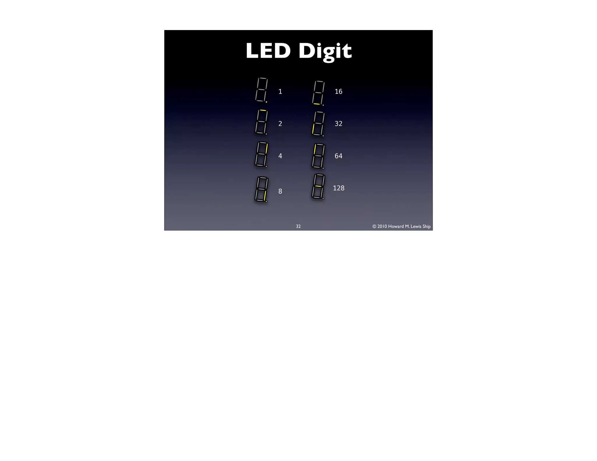
B01111110, // 0
B00001100, // 1
B10110110, // 2
B10011110, // 3
B11001100, // 4
B11011010, // 5
B11111010, // 6
B00001110, // 7
B11111110, // 8
B11001110, // 9
B10111110, // A
B11111000, // B
B10110000, // C
B10111100, // D
B11110010, // E
B11100010 // F
};
34 © 2010 Howard M. Lewis Ship](https://image.slidesharecdn.com/oscon-2010-arduino-100721100309-phpapp01/75/Arduino-Open-Source-Hardware-Hacking-from-the-Software-Nerd-Perspective-34-2048.jpg)
![void writeDigit(byte value, boolean showDP)
{
// Ignore all but the low 4 bits when indexing
byte digit = digits[value & 0x0f];
// Decimal point is LSB
if (showDP)
digit |= 1;
shiftOut(dataPin, clockPin, MSBFIRST, digit);
}
35 © 2010 Howard M. Lewis Ship](https://image.slidesharecdn.com/oscon-2010-arduino-100721100309-phpapp01/75/Arduino-Open-Source-Hardware-Hacking-from-the-Software-Nerd-Perspective-35-2048.jpg)


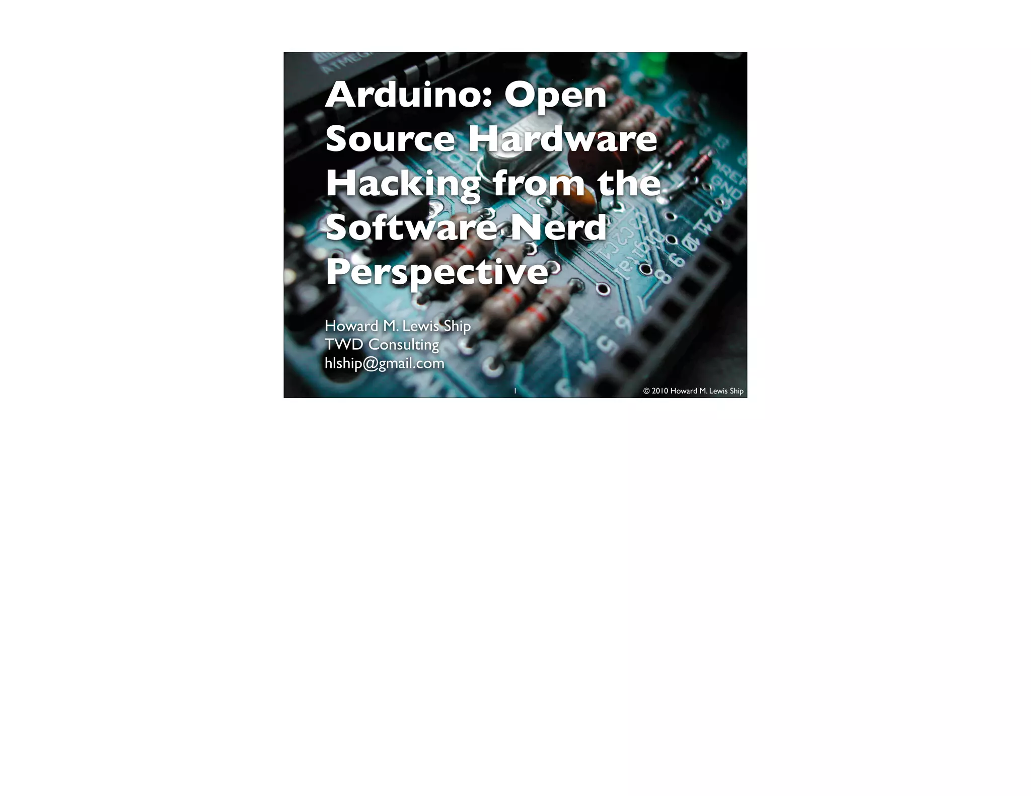
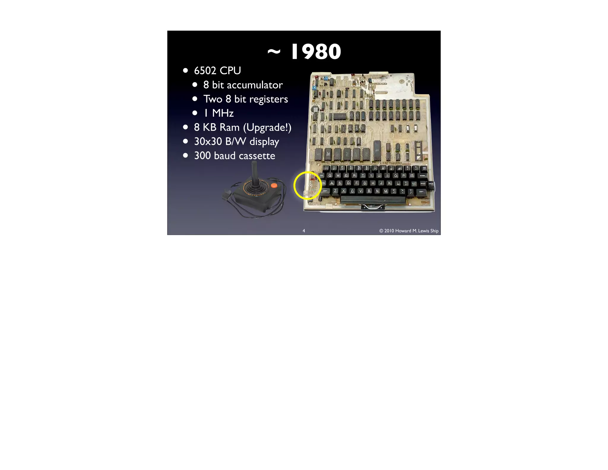
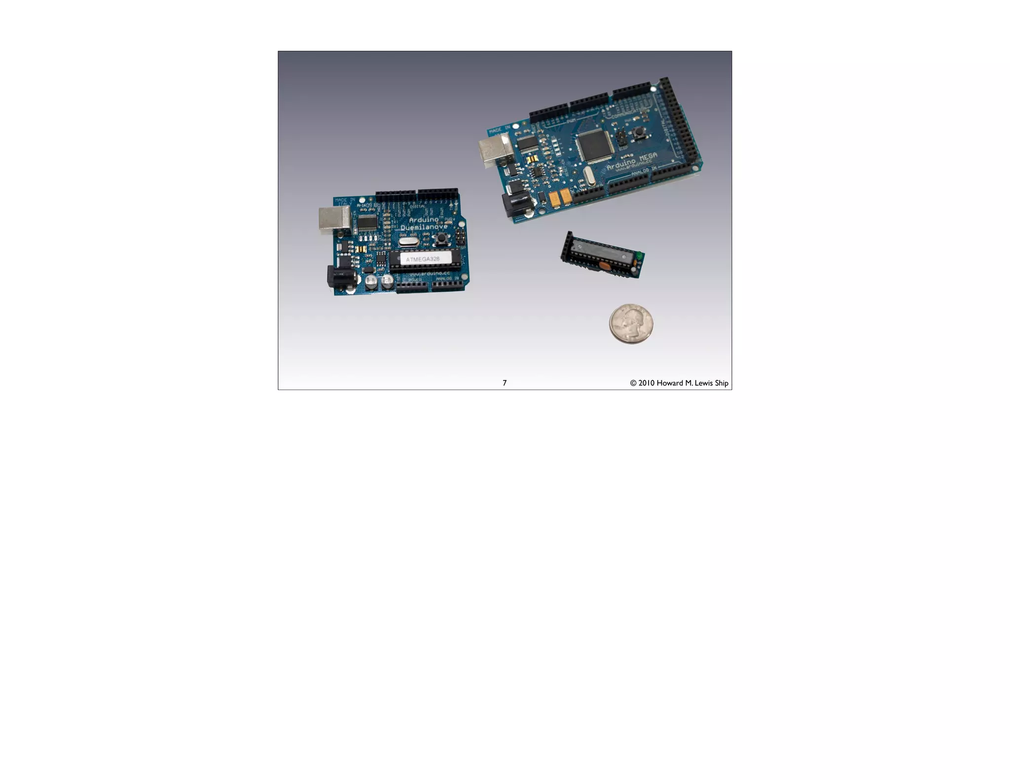
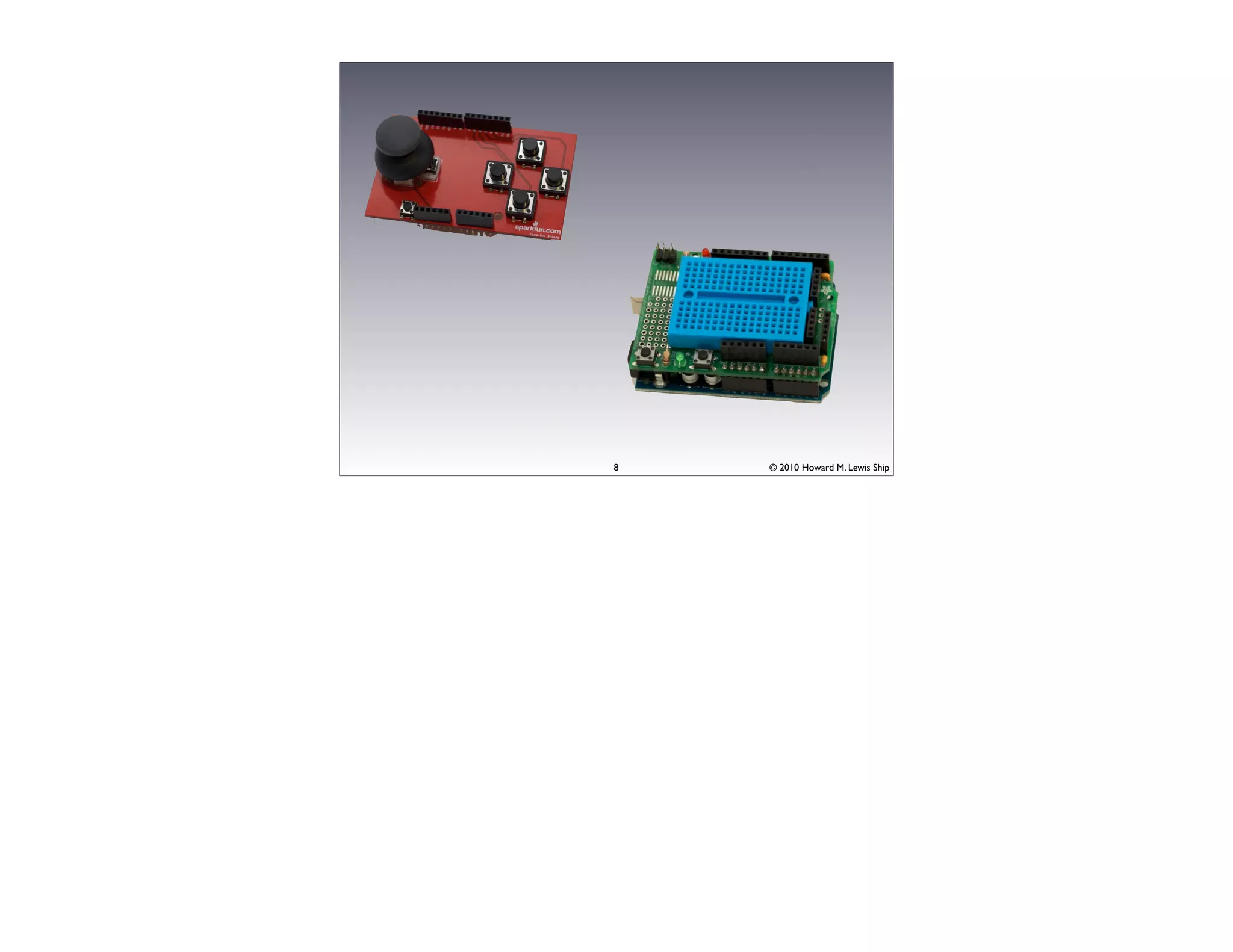
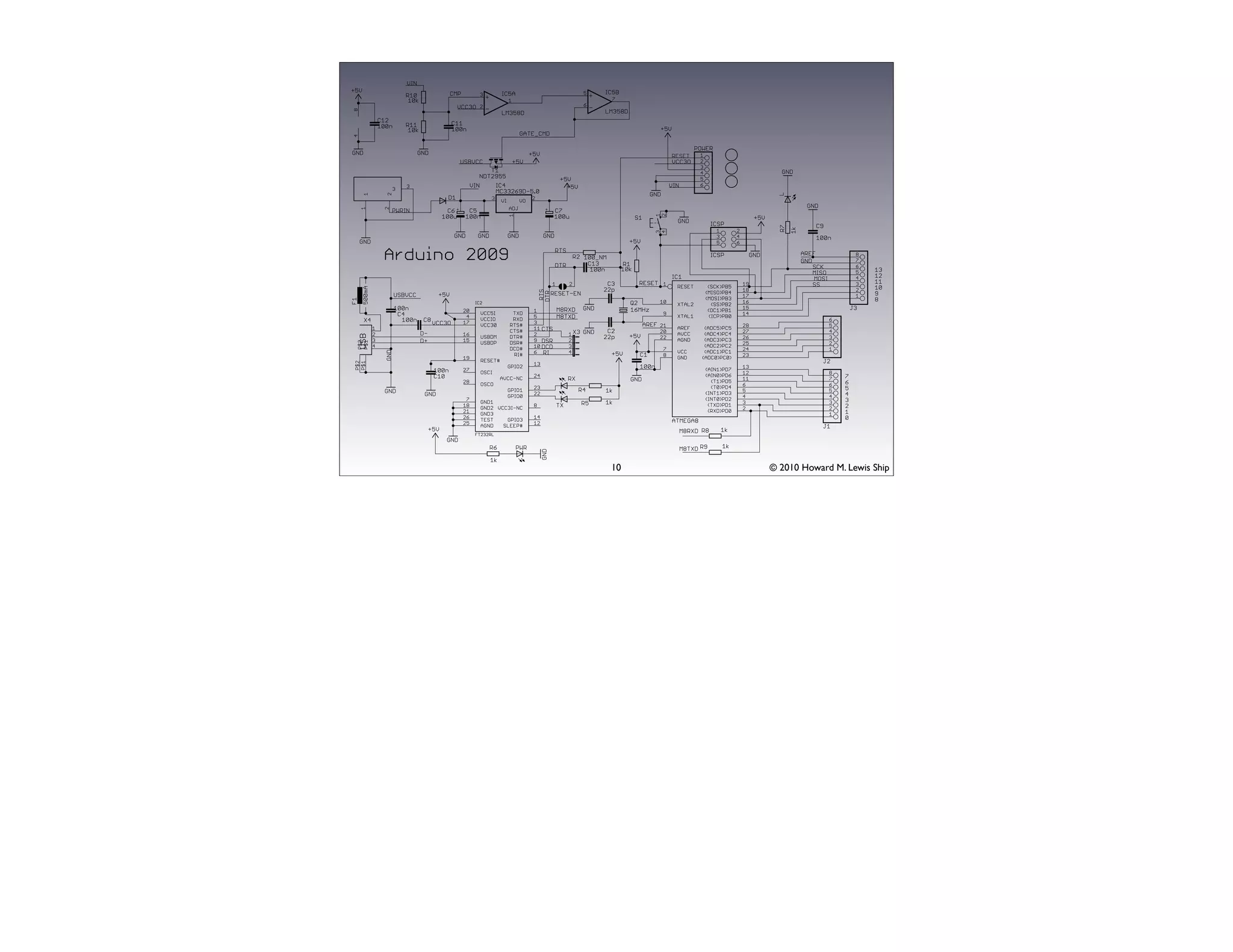
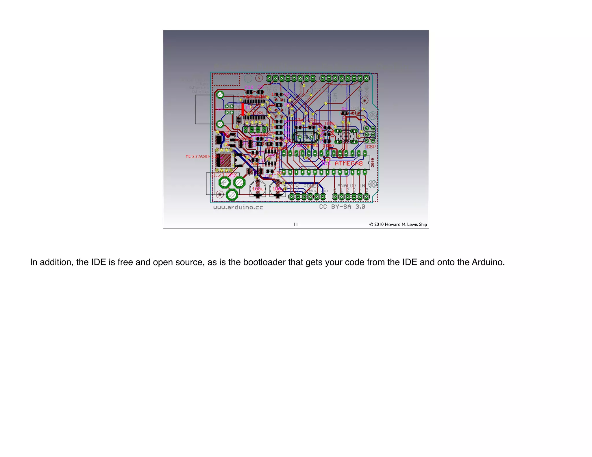
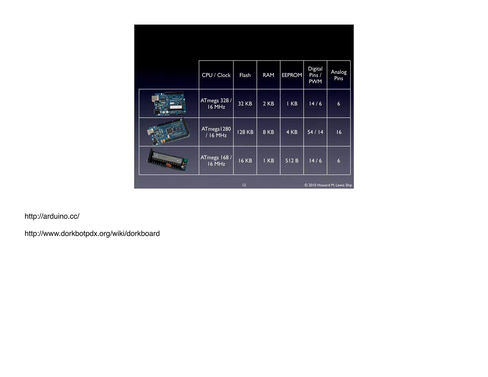
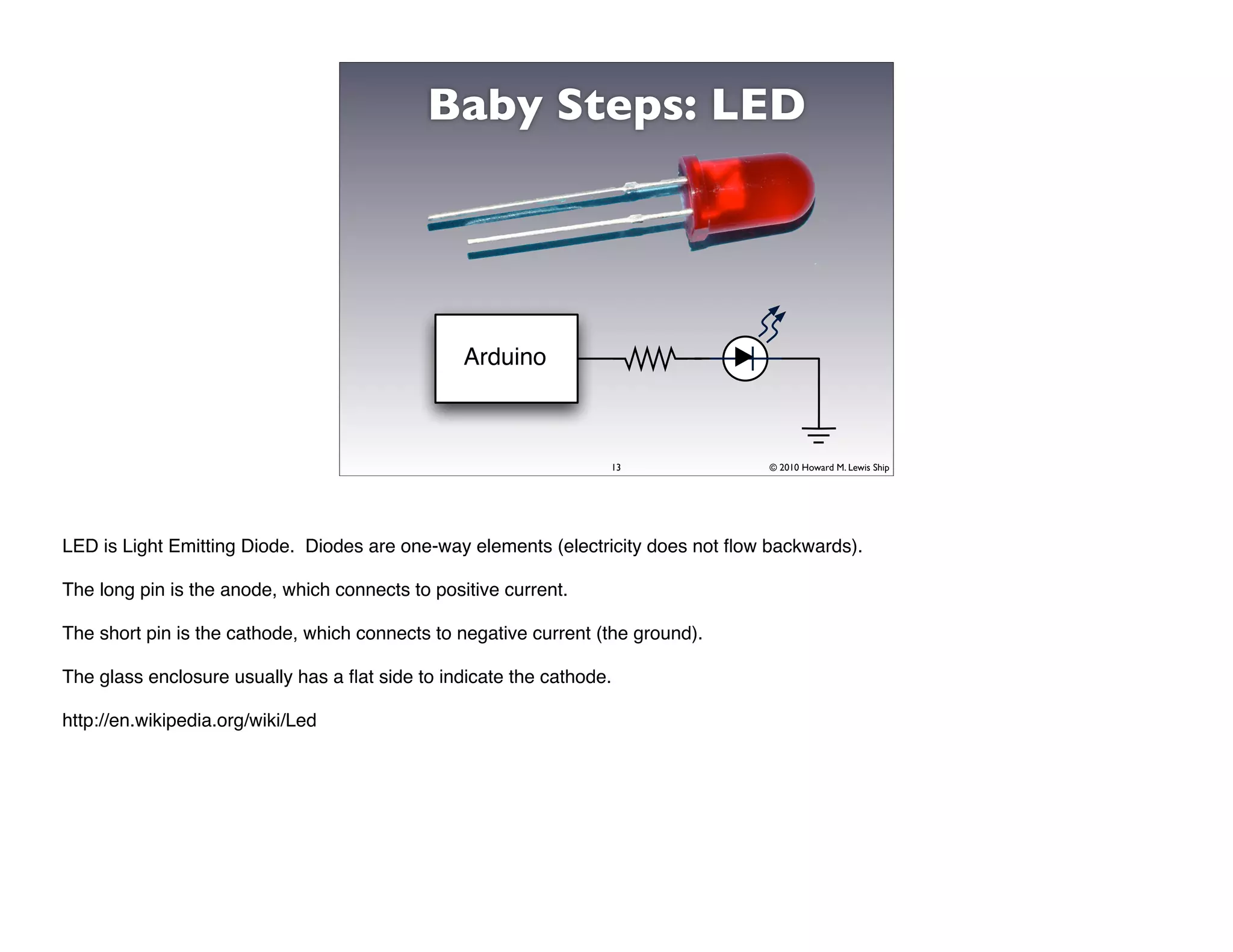
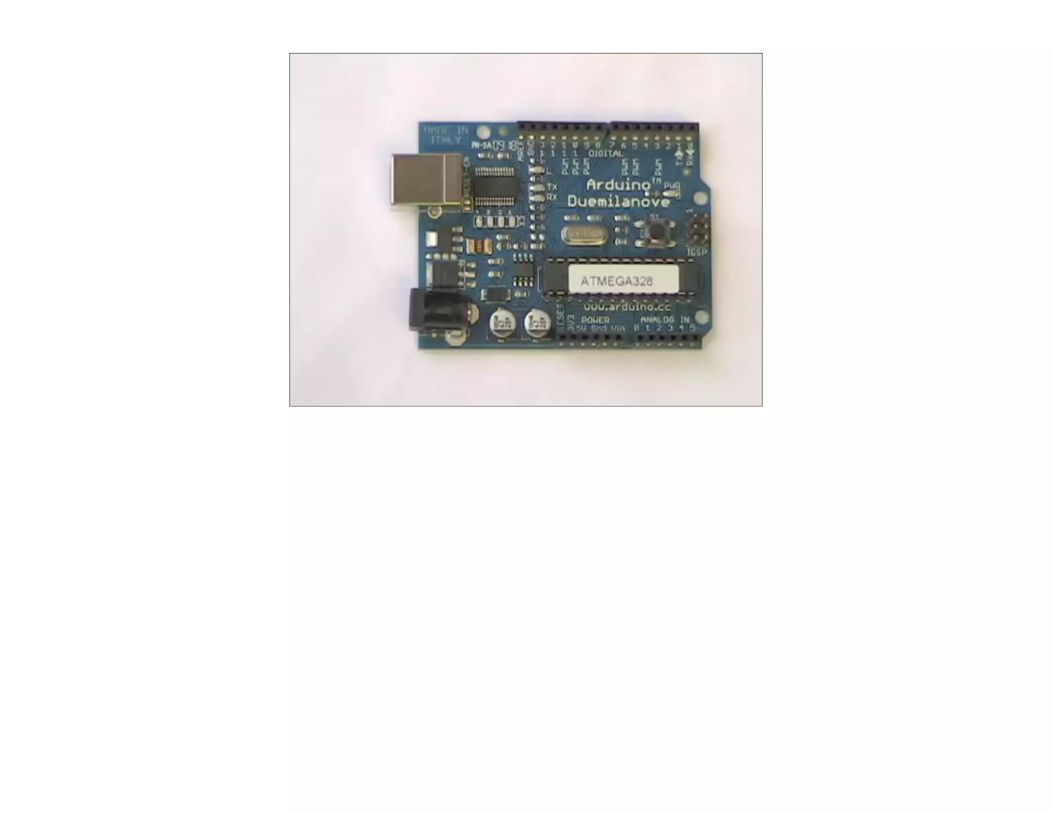
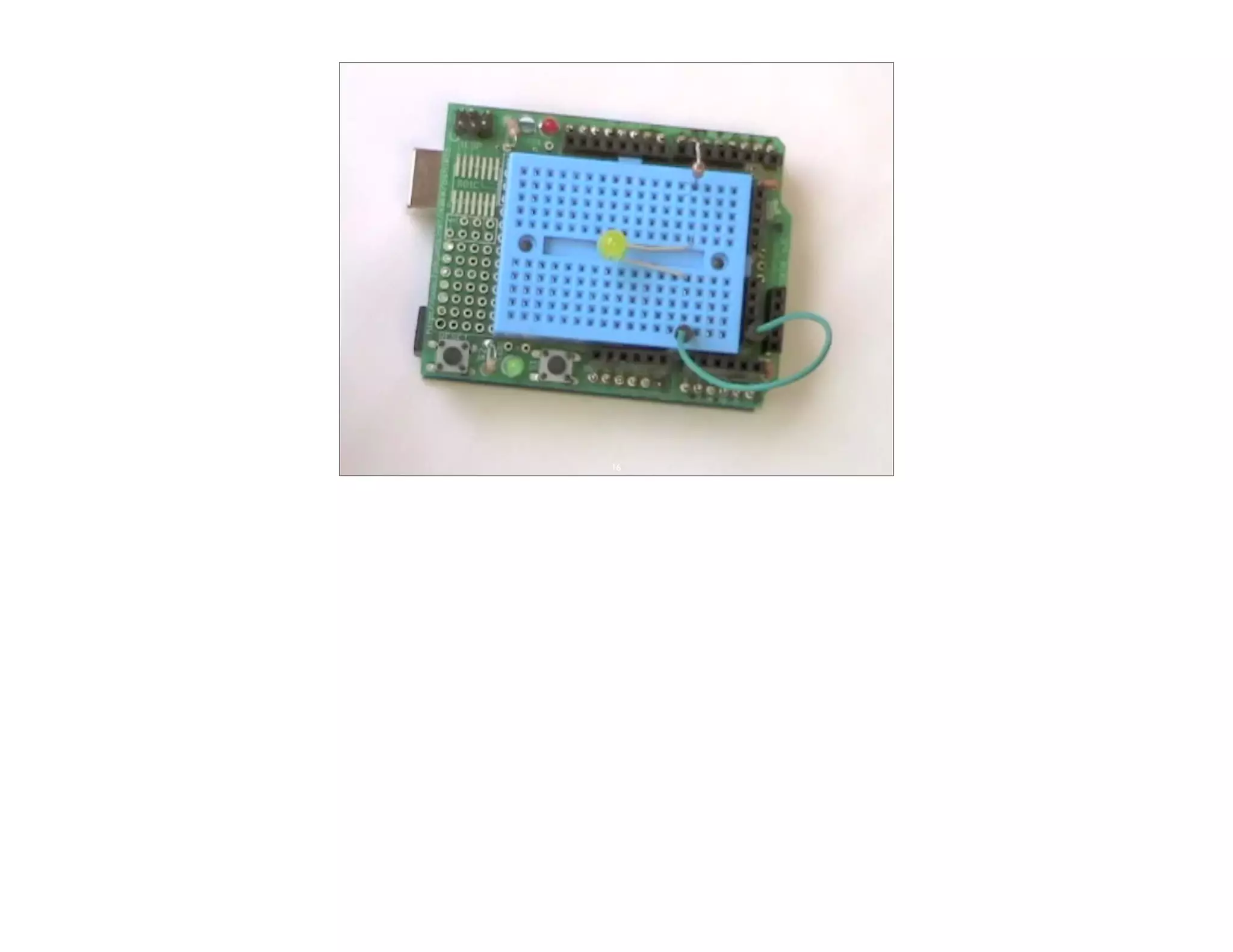
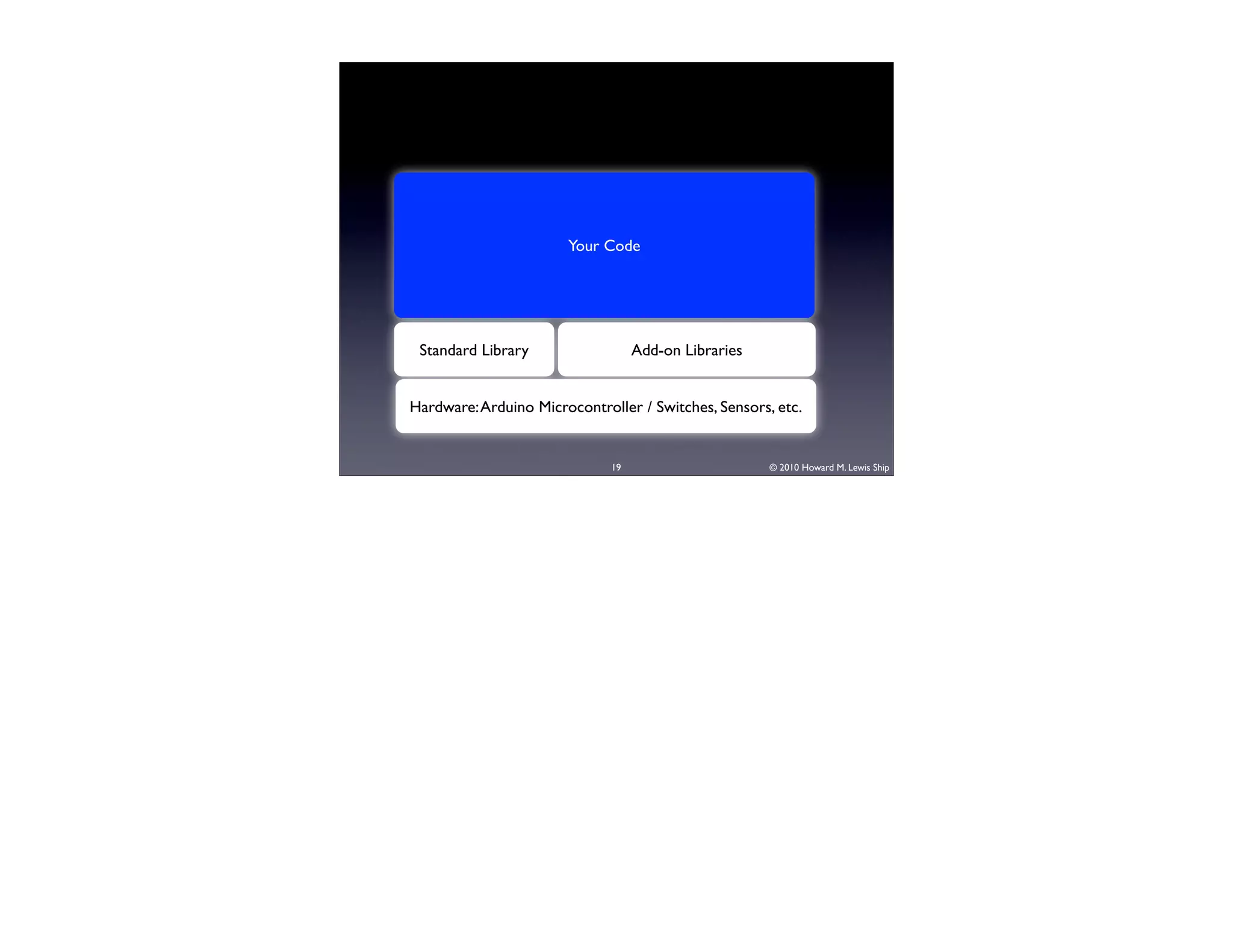
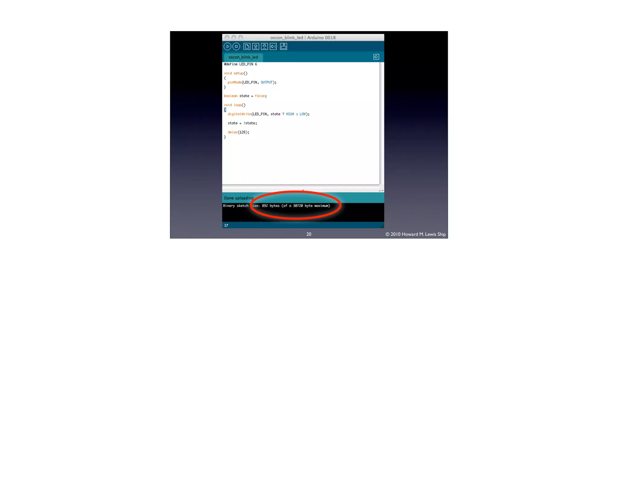
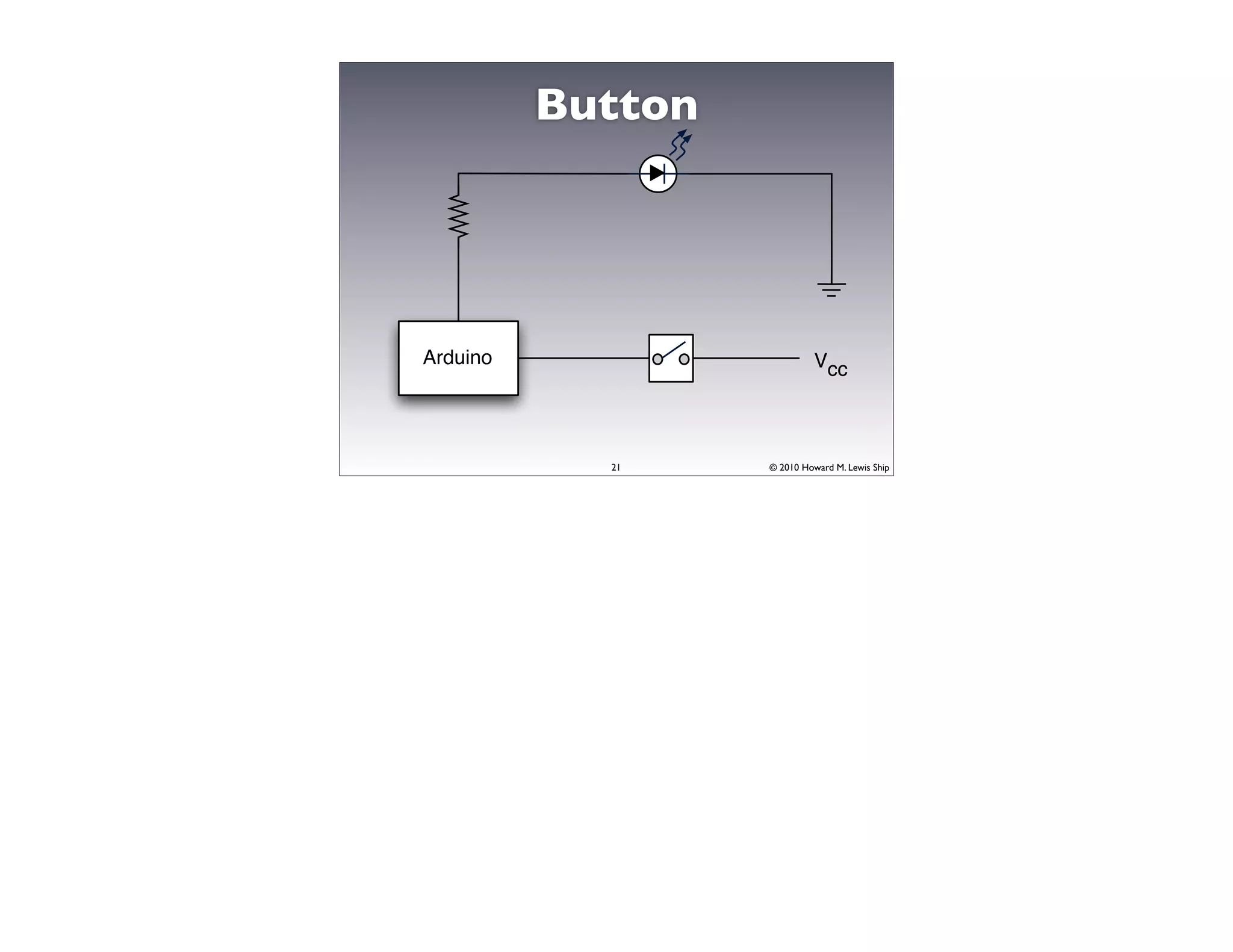
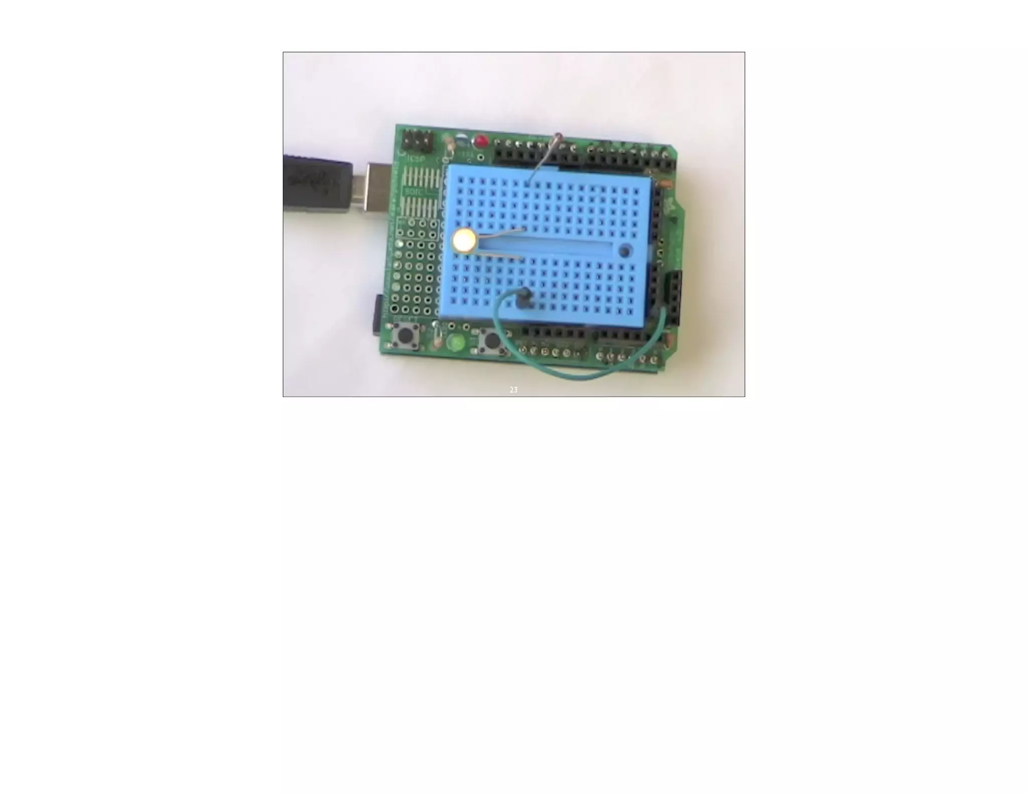
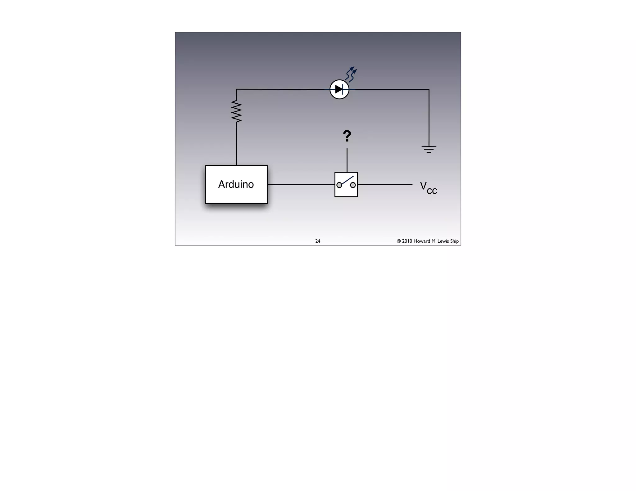
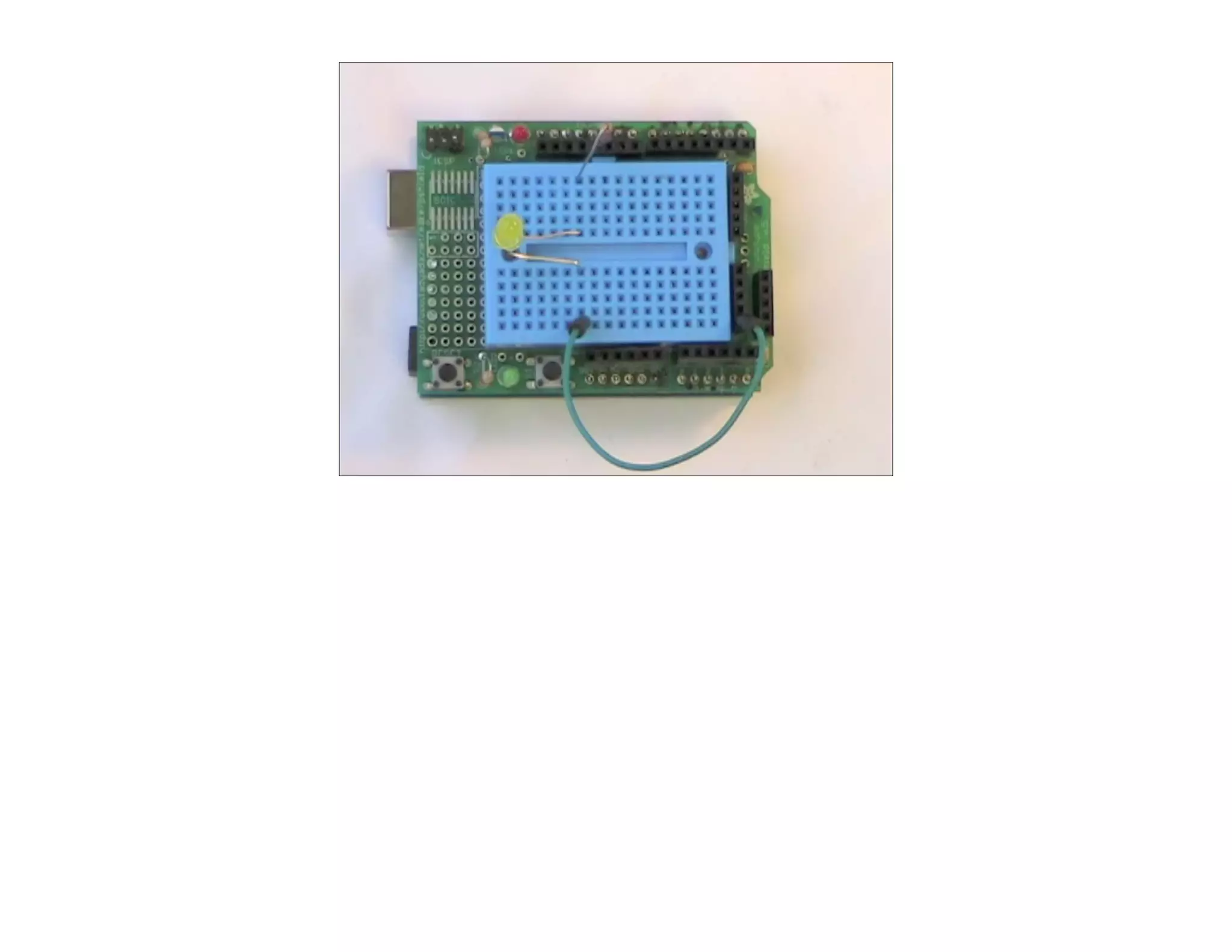
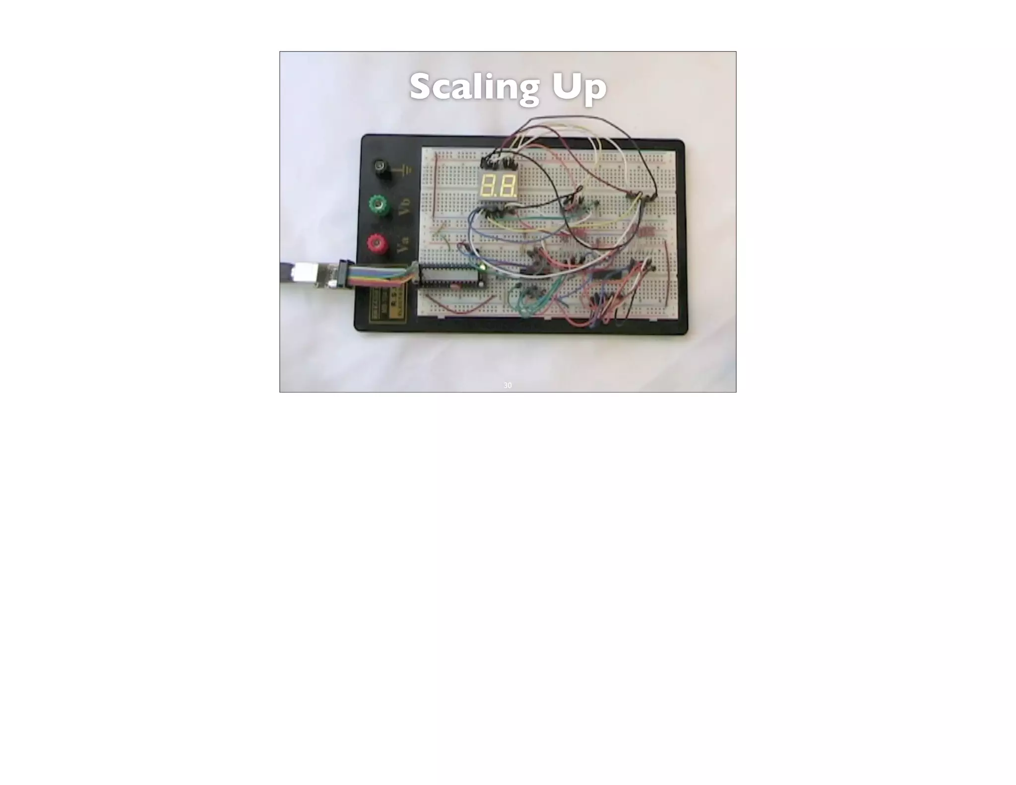
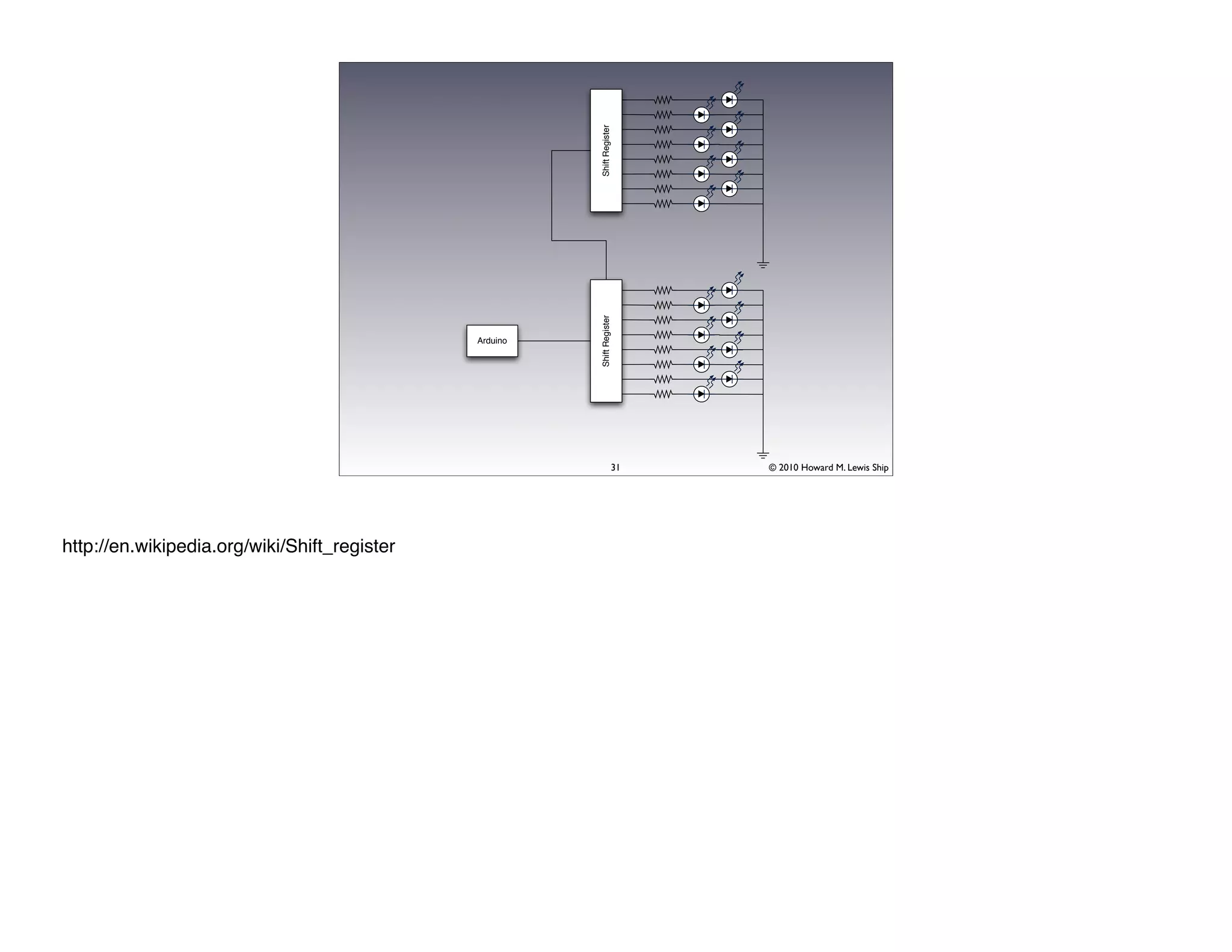
This document discusses Arduino open source hardware from the perspective of a software developer. It provides an overview of Arduino boards and their specifications. It then demonstrates some basic Arduino projects like blinking an LED and reading input from a button or potentiometer. It also covers scaling up projects using shift registers and discusses next steps of using more sensors and displays. The goal is to show how easy it is for software developers to get started with Arduino and physical computing.


![[CB16] COFI break – Breaking exploits with Processor trace and Practical cont...](https://cdn.slidesharecdn.com/ss_thumbnails/cb16shinaen-161108081131-thumbnail.jpg?width=640&height=640&fit=bounds)