The document discusses applied thermal engineering including power plant engineering, types of boilers, and internal and external combustion engines. It covers the principles of steam production, boiler classifications, types of turbines, and the working mechanisms of both four-stroke and two-stroke engines. Additionally, it includes comparisons between water tube and fire tube boilers, as well as between internal combustion engines and their classifications based on various criteria.
![Unit VI
Applied Thermal Engineering
Power Plant Engineering: Conventional and non-conventional energy resources, Hydro-electric,
Thermal, Nuclear. Wind, Solar [with Block diagram].
Power Producing Devices: Boiler - Water tube and lire tube. Internal combustion engine - Two stroke
and four stroke (Spark ignition and compression ignition). Turbines - Impulse and reaction.
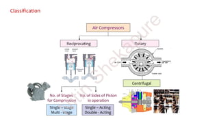
Power Absorbing Devices: Pump - Reciprocating and Centrifugal, Compressor - Single acting, single
stage reciprocating air compressor, Refrigeration - Vapour compression refrigeration process, House
hold refrigerator. Window air conditioner (Working with block diagrams).
N
itin
Shekapure](https://image.slidesharecdn.com/bmeunitvibynitinshekapure-191002025354/85/Applied-Thermal-Engineering-2-320.jpg)