Download to read offline
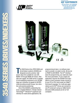


The 3540 Series drive and drive/indexer systems are designed for precision motion control of NEMA 14 through 34 motors. They offer microstepping resolutions up to 50,800 steps per revolution at speeds up to 50 revolutions per second. The Si3540 indexer features a graphical user interface that allows programming by point-and-click without coding. It can connect to a PC or operate independently, controlling up to 8 axes. The drives are CE and TUV compliant for industrial applications.


