Download to read offline

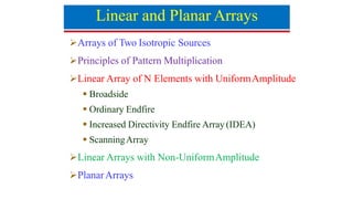
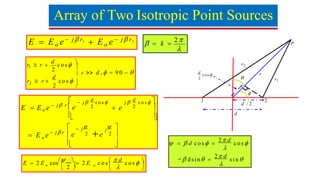
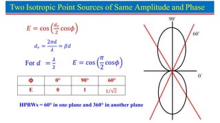

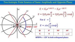
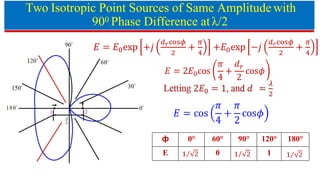
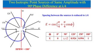

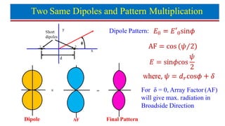

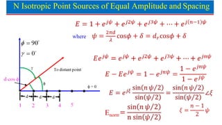
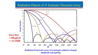
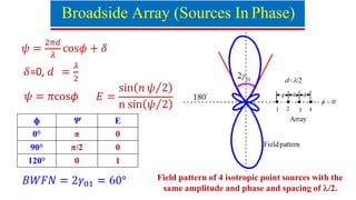
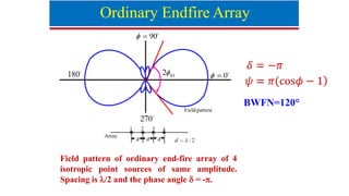
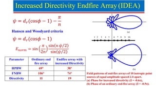

The document discusses the principles and configurations of linear and planar antenna arrays, including isotropic sources and their radiation patterns. It covers concepts like pattern multiplication, directivity in endfire arrays, and varying amplitudes and phases between sources. Additionally, it outlines the effects of spacing and phase differences on radiation patterns for arrays of isotropic point sources.

![3_Antenna Array [Modlue 4] (1).pdf](https://cdn.slidesharecdn.com/ss_thumbnails/3antennaarraymodlue41-220419112111-thumbnail.jpg?width=640&height=640&fit=bounds)