SlideShare a Scribd company logo
REPORT
(ELECTRIC AEC FURNACE, MELTING, HEAT TREATMENT)
NAME: ANKU KUMAR PANDEY INDUSTRY NAME: -
COLLEGE NAME: SS COLLEGE OF ENGINEERING, TITAGARG WAGON LTD.
 What is a furnace:-
▪ A furnace is essentially a thermal enclosure and is employed to process raw materials at
high temperatures both in solid state and liquid state.
▪ Several industries like iron and steel making, nonferrous metals production, glass
making, manufacturing, ceramic processing, calcination in cement production etc.
a) To utilize heat efficiently so that losses are minimum, and
b) To handle the different phases (solid, liquid or gaseous) moving at different velocities for
different times and temperatures such that erosion and corrosion of the refractory are
minimum.
 What are the components of a furnace:-
i Source of energy
a) Fossil fuel: For fossil fuel one requires burner for efficient mixing of fuel and air.
Arrangement of burner is important.
b) Electric energy: Resistance heating, induction heating or arc heating.
c) Chemical energy: Exothermic reactions
ii. Suitable refractory material: Refractory design is important. Thermal enclosure of
the furnace is designed and constructed keeping in view the requirements.
For example refractory facing the thermal enclosure must have high refractoriness,
chemically inert etc.
Whereas refractory facing the surrounding must have low thermal conductivity to
minimize heat losses.
iii. Heat exchanger: Heat exchanger is becoming now as part of the fossil fuel fired
furnaces in order to recover and reuse the heat of POC.
Heat of POC can be used either external to furnace by installing a heat exchanger or
internally by recirculation the POC within the furnace.
 Type of Electric furnaces:
▪ In principle an electric arc is formed between the electrode and the metallic charge and
charge is heated from the arc radiation.
▪ Electric arc furnaces are of two type (a) alternating current and (b) direct current. In
alternating current, furnace operates by means of electric current flowing from one
electrode of three to another through the metallic charge.
▪ In direct current, the current flows from carbon electrode, which acts as cathode, to an
anode embedded in the bottom of the furnace.
 Construction of AC Electric Arc Furnace
▪ The furnace consists of a steel shell, lined with suitable refractory materials and is
mounted on the tilting mechanism.
▪ The shell thickness is around 0.005 times the shell diameter. Three electrodes enter
through the roof.
▪ The hood may be swung away for charging. Heat is generated by the hot area formed
between the electrodes and the charge.
Hearth
▪ The hearth contains metal and slag.
▪ The hearth lining consists of backing lining and working lining.
▪ The backing lining is few layers of high fired magnesite bricks on which working lining
is rammed with either dolomite or magnesite mass.
▪ Permeable blocks or porous refractory elements are introduced through the bottom to
inject inert gas for stirring.
▪ The EAF steel bath is shallow; the aspect ratio of the bath is around 0.2 to 0.22.
Roof
▪ The roof isexposedtomore heatthan otherfurnace elements.
▪ Its liningisalsosubjectedtoradiantheatreflectedfromthe wallsandslag.
▪ Highaluminabricksand magnesite - chromite bricksare usedforroof lining.
▪ The roof liningiswatercooledwhichincreasesthe lifeof refractoryliningtoat least10-20 times
more than withoutwatercooling.
Electrode
▪ A typical alternatingcurrentoperatedEAFhasthree electrodes.
▪ Electrodesare roundinsection,andtypicallyinsegmentswiththreadedcoupling,sothatas the
electrodeswear,new segmentscanbe added.
▪ Graphite electrodesare preferredovercarbonelectrodesbecauseof betterelectrical
conductivity.
▪ The electrodesare automaticallyraisedandloweredbyapositioningsystem.
 Electrode consumption depends on
• Oxidation of the surface of the electrode
• Mechanical losses due to fracture
• Dissolution in slag during carbon boil
▪ The diameter of the electrode should correspond to the current supplied; if current density
is excessively high, electrodes will be heated and oxidized vigorously.
▪ The electrode current could vary from 12 to 16A⁄cm2 for 400 to 600 m electrode
diameter. Larger electrode diameter increases electric energy consumption.
▪ The electrodes are positioned at apexes of an equilateral triangle.
▪ The diameter of the circle passing through the centers of electrodes is called the diameter
of the electrode spacing.
▪ If the electrodes are placed close to each other and far from furnace walls, the charge at
the furnace banks will be heated belatedly.
▪ With large spacing diameter, electric arcs will burn near the walls, which will result in
rapid wear of the lining.
▪ The electrode spacing diameter for the bath diameter could be 0.45 for small furnaces,
0.35 for medium- sized and large furnaces, and still lower for super- powerful furnaces.
For a bath diameter of 5560 mm of a 100 ton furnace the electrode spacing diameter
would be 0.35 × 5560 = 1900mm.
Side walls
▪ The side walls refractory materials should be able to withstand thermal shock and
corrosive action of slag.
▪ Hot spot is formed on the side walls due to the radiation from arc flames, reflected from
bath surface during power input.
▪ The side wall is lined with magnesite or dolomite or chrome magnesite bricks up to the
slag line.
▪ The side wall thickness is usually 450 to 500mm for 10 to 50 ton furnaces and 550 to
650mm for 100 to 200 ton furnaces.
Transformer power:
▪ Electric furnaces are powerful consumers of electric energy.
▪ The operating voltage of a furnace is 100-800V and the current may reach several
thousand amperes.
▪ The furnace transformer high voltage energy into low voltage.
 The melting process consists of two periods:
Melt down and refining period.
▪ In melt down period higher electric energy is required as compared with the refining
period.
▪ In small furnaces, the power consumption for melting is about 600kWh⁄ton and it
falls to 450kWh⁄ton in big furnaces.
▪ Additional 150 to 400kWh⁄ton power is required during refining depending on the
practice.
▪ Large transformers are required to run electric arc furnaces.
▪ During melting more power is required than during refining. The transformer capacity is
designed to suit melting requirements.
▪ The capacity of the transformer is usually 470- 650 KVA per ton of furnace capacity.
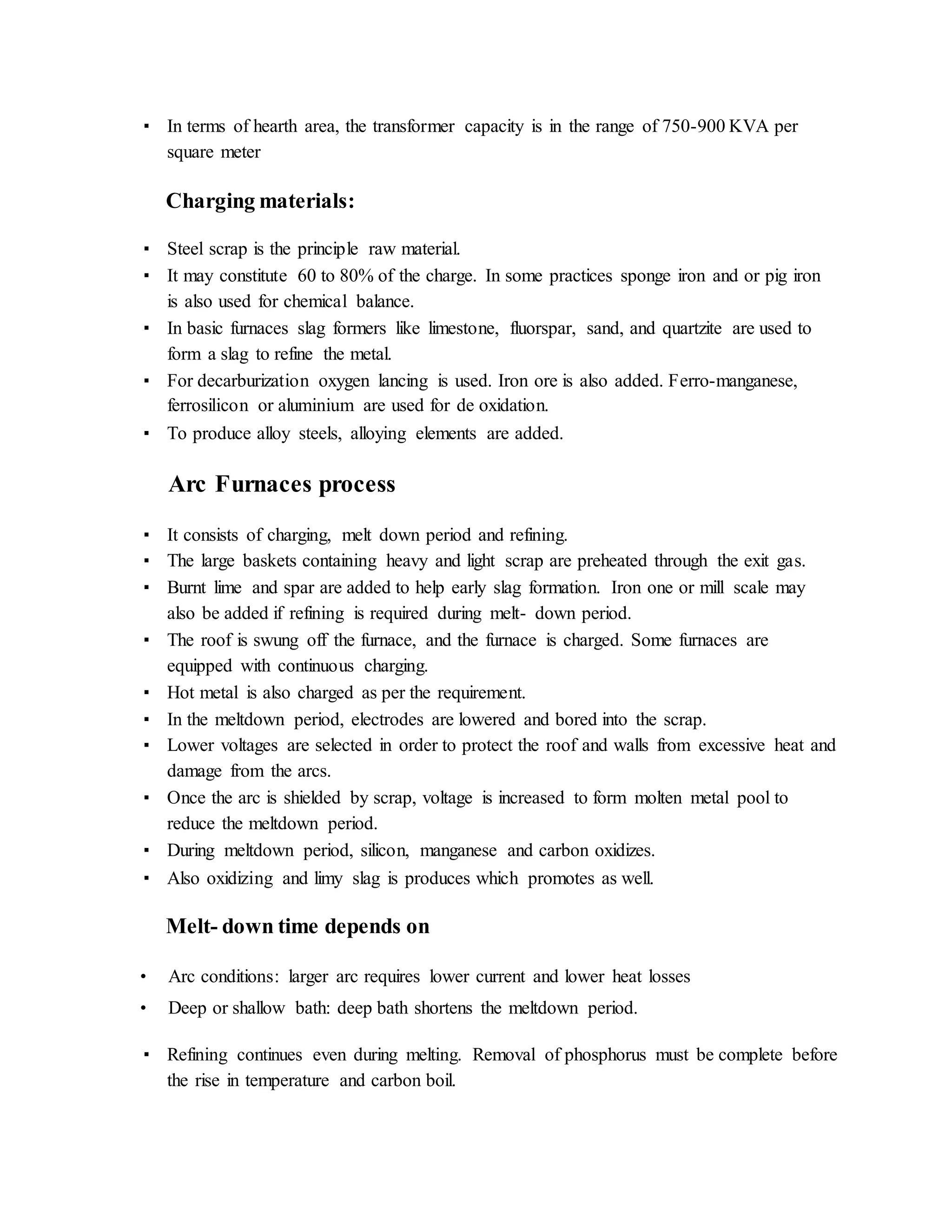
▪ In terms of hearth area, the transformer capacity is in the range of 750-900 KVA per
square meter
Charging materials:
▪ Steel scrap is the principle raw material.
▪ It may constitute 60 to 80% of the charge. In some practices sponge iron and or pig iron
is also used for chemical balance.
▪ In basic furnaces slag formers like limestone, fluorspar, sand, and quartzite are used to
form a slag to refine the metal.
▪ For decarburization oxygen lancing is used. Iron ore is also added. Ferro-manganese,
ferrosilicon or aluminium are used for de oxidation.
▪ To produce alloy steels, alloying elements are added.
Arc Furnaces process
▪ It consists of charging, melt down period and refining.
▪ The large baskets containing heavy and light scrap are preheated through the exit gas.
▪ Burnt lime and spar are added to help early slag formation. Iron one or mill scale may
also be added if refining is required during melt- down period.
▪ The roof is swung off the furnace, and the furnace is charged. Some furnaces are
equipped with continuous charging.
▪ Hot metal is also charged as per the requirement.
▪ In the meltdown period, electrodes are lowered and bored into the scrap.
▪ Lower voltages are selected in order to protect the roof and walls from excessive heat and
damage from the arcs.
▪ Once the arc is shielded by scrap, voltage is increased to form molten metal pool to
reduce the meltdown period.
▪ During meltdown period, silicon, manganese and carbon oxidizes.
▪ Also oxidizing and limy slag is produces which promotes as well.
Melt- down time depends on
• Arc conditions: larger arc requires lower current and lower heat losses
• Deep or shallow bath: deep bath shortens the meltdown period.
▪ Refining continues even during melting. Removal of phosphorus must be complete before
the rise in temperature and carbon boil.
▪ The single oxidizing slag practice is employed when removal of sulphar is not required.
▪ When both P and S are required to be removed double slag practice is used.
▪ In double slag practice, oxidizing slag is removed and reducing slag is formed after de
oxidation with ferrosilicon or ferromanganese or aluminum.
▪ Reducing slag helps to avoid loss
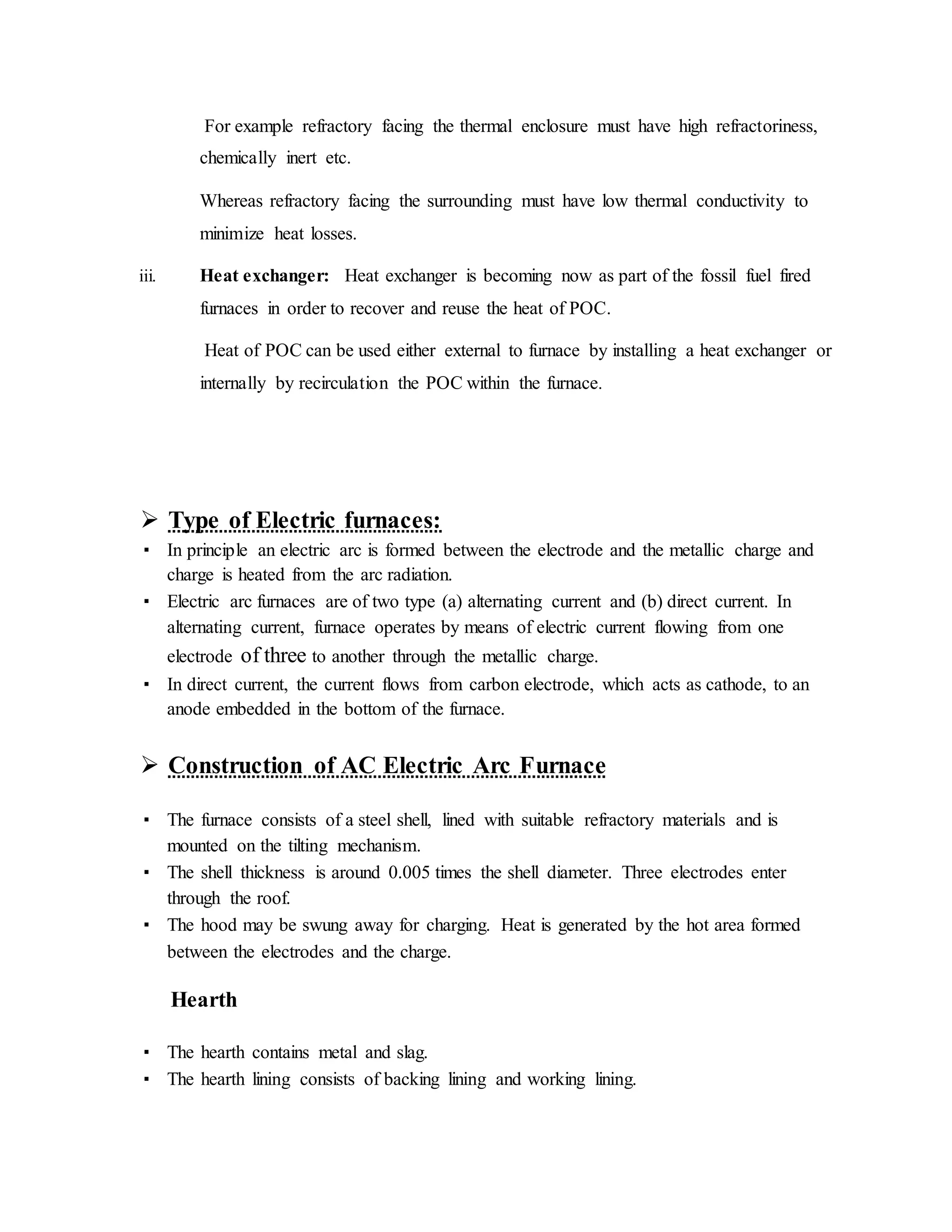
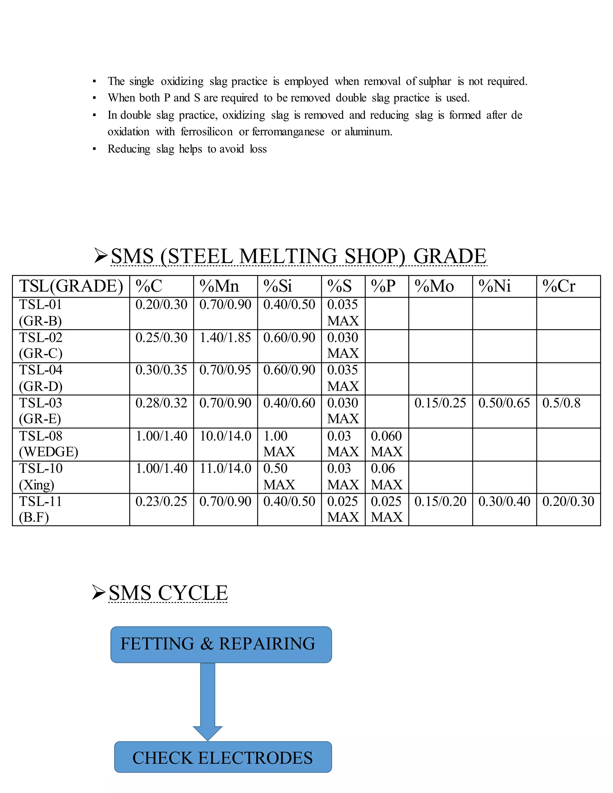
SMS (STEEL MELTING SHOP) GRADE
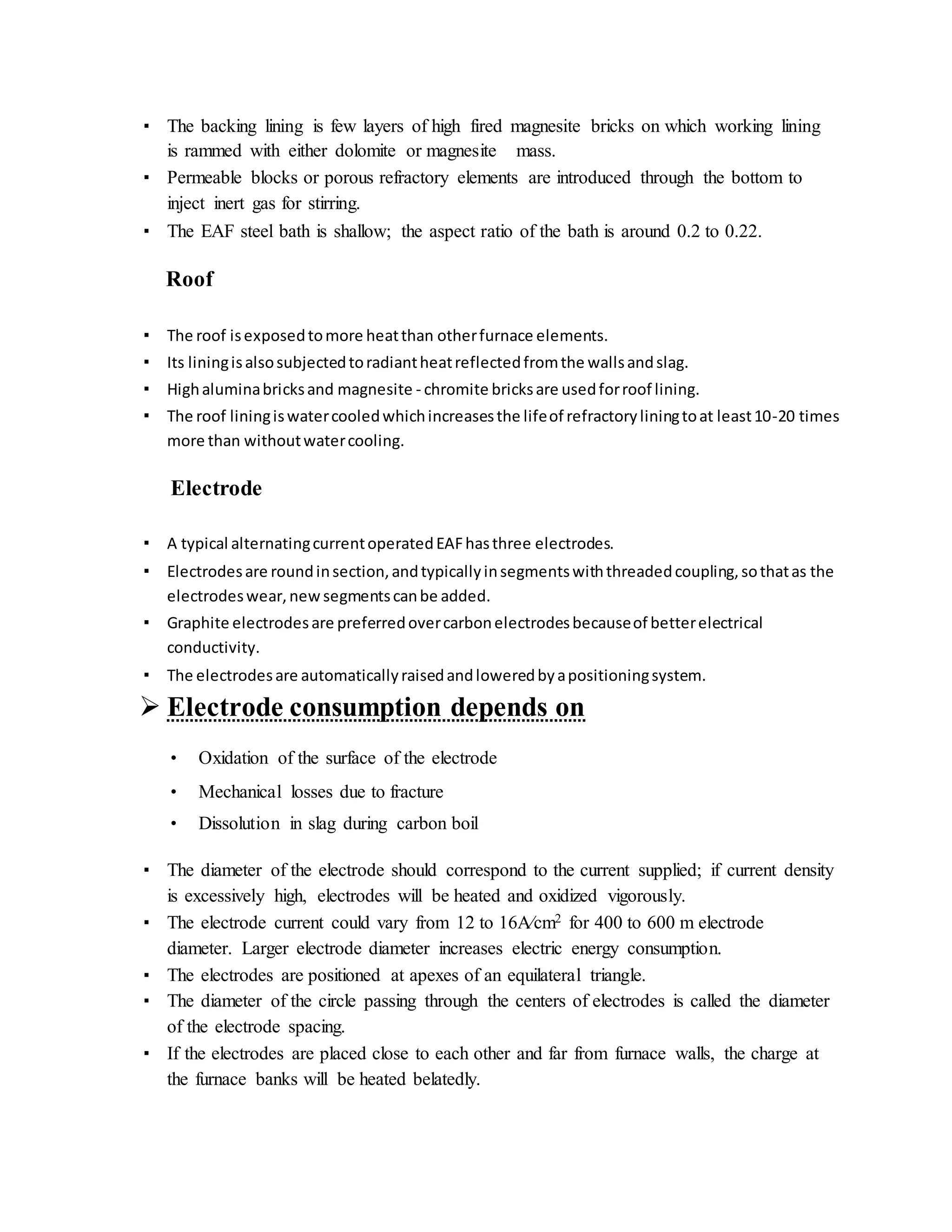
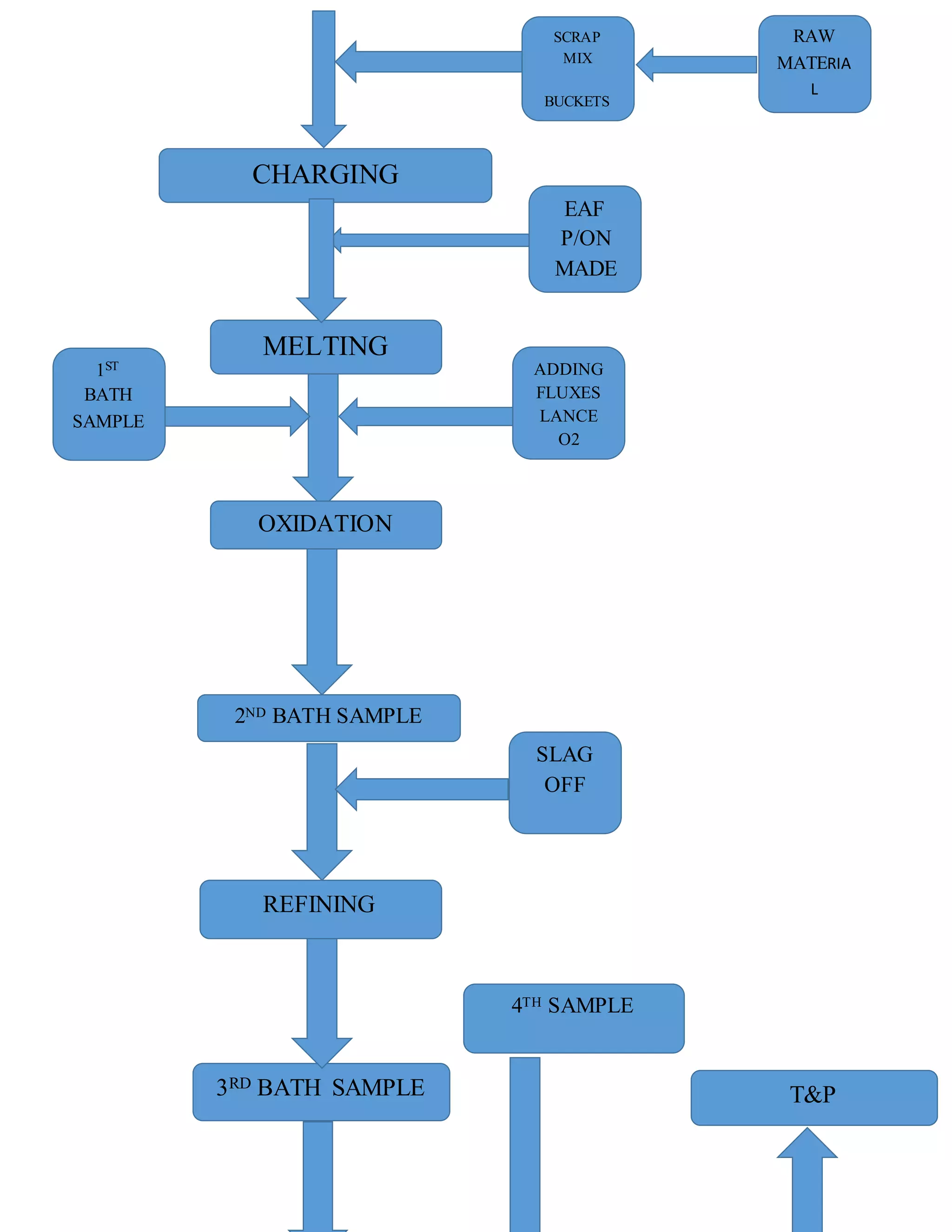
SMS CYCLE
TSL(GRADE) %C %Mn %Si %S %P %Mo %Ni %Cr
TSL-01
(GR-B)
0.20/0.30 0.70/0.90 0.40/0.50 0.035
MAX
TSL-02
(GR-C)
0.25/0.30 1.40/1.85 0.60/0.90 0.030
MAX
TSL-04
(GR-D)
0.30/0.35 0.70/0.95 0.60/0.90 0.035
MAX
TSL-03
(GR-E)
0.28/0.32 0.70/0.90 0.40/0.60 0.030
MAX
0.15/0.25 0.50/0.65 0.5/0.8
TSL-08
(WEDGE)
1.00/1.40 10.0/14.0 1.00
MAX
0.03
MAX
0.060
MAX
TSL-10
(Xing)
1.00/1.40 11.0/14.0 0.50
MAX
0.03
MAX
0.06
MAX
TSL-11
(B.F)
0.23/0.25 0.70/0.90 0.40/0.50 0.025
MAX
0.025
MAX
0.15/0.20 0.30/0.40 0.20/0.30
FETTING & REPAIRING
CHECK ELECTRODES
CHARGING
SCRAP
MIX
BUCKETS
RAW
MATERIA
L
MELTING
EAF
P/ON
MADE
1ST
BATH
SAMPLE
ADDING
FLUXES
LANCE
O2
OXIDATION
2ND BATH SAMPLE
REFINING
SLAG
OFF
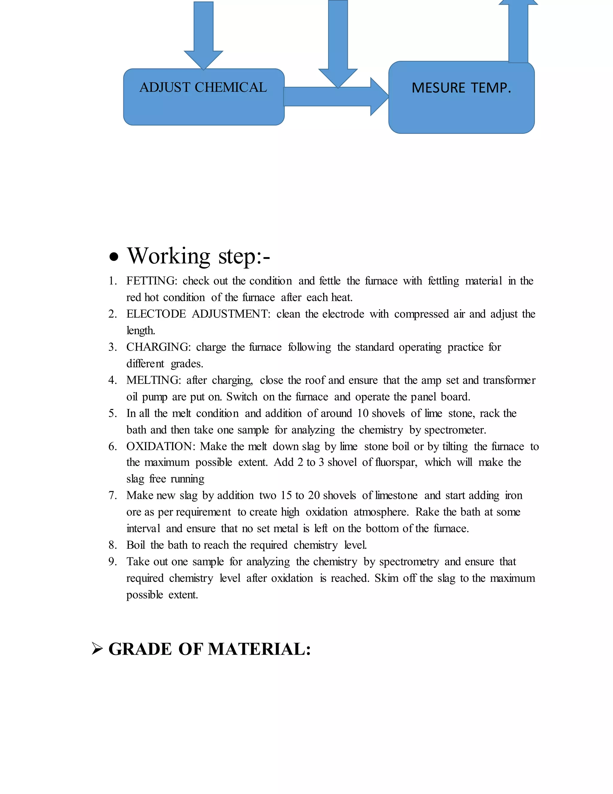
3RD BATH SAMPLE T&P
4TH SAMPLE
 Working step:-
1. FETTING: check out the condition and fettle the furnace with fettling material in the
red hot condition of the furnace after each heat.
2. ELECTODE ADJUSTMENT: clean the electrode with compressed air and adjust the
length.
3. CHARGING: charge the furnace following the standard operating practice for
different grades.
4. MELTING: after charging, close the roof and ensure that the amp set and transformer
oil pump are put on. Switch on the furnace and operate the panel board.
5. In all the melt condition and addition of around 10 shovels of lime stone, rack the
bath and then take one sample for analyzing the chemistry by spectrometer.
6. OXIDATION: Make the melt down slag by lime stone boil or by tilting the furnace to
the maximum possible extent. Add 2 to 3 shovel of fluorspar, which will make the
slag free running
7. Make new slag by addition two 15 to 20 shovels of limestone and start adding iron
ore as per requirement to create high oxidation atmosphere. Rake the bath at some
interval and ensure that no set metal is left on the bottom of the furnace.
8. Boil the bath to reach the required chemistry level.
9. Take out one sample for analyzing the chemistry by spectrometry and ensure that
required chemistry level after oxidation is reached. Skim off the slag to the maximum
possible extent.
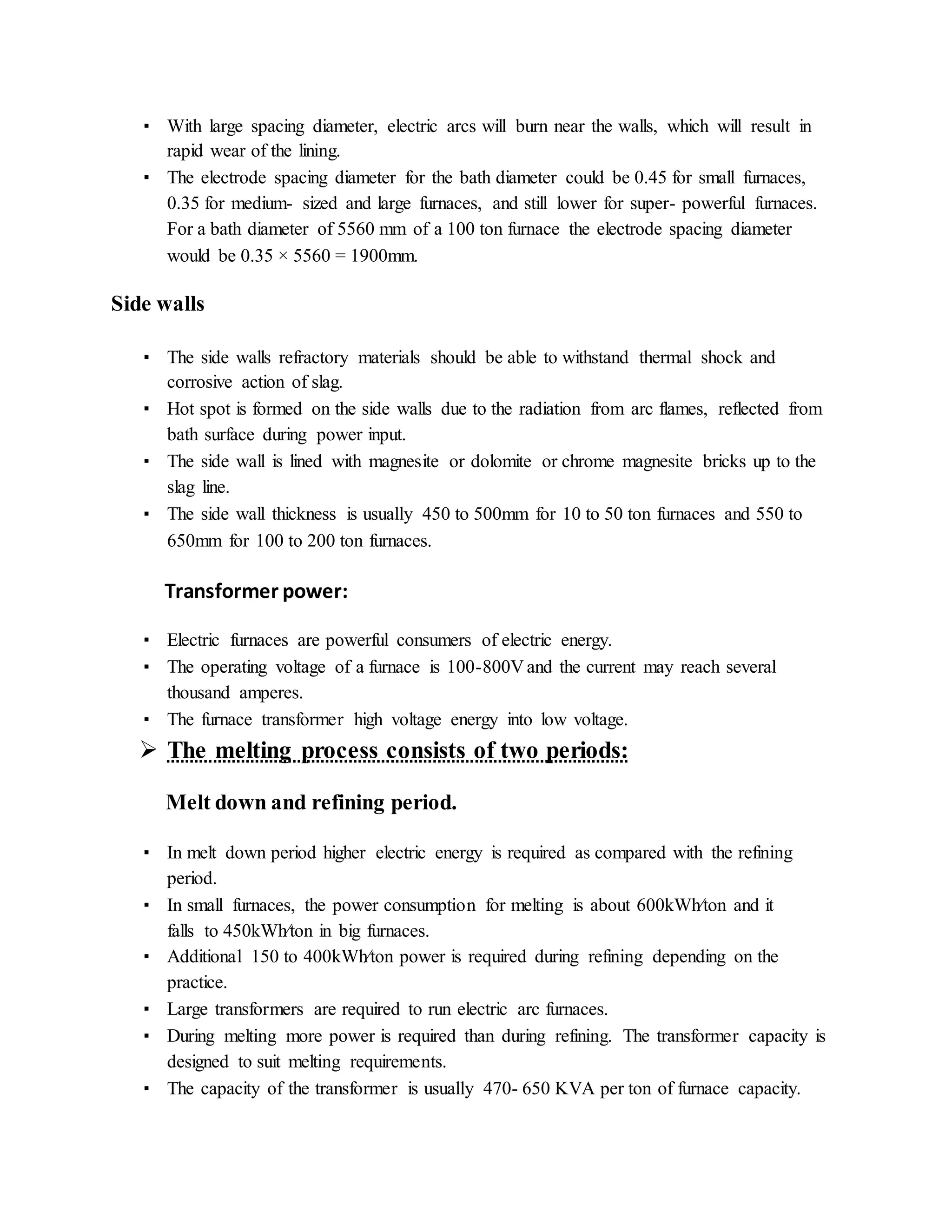
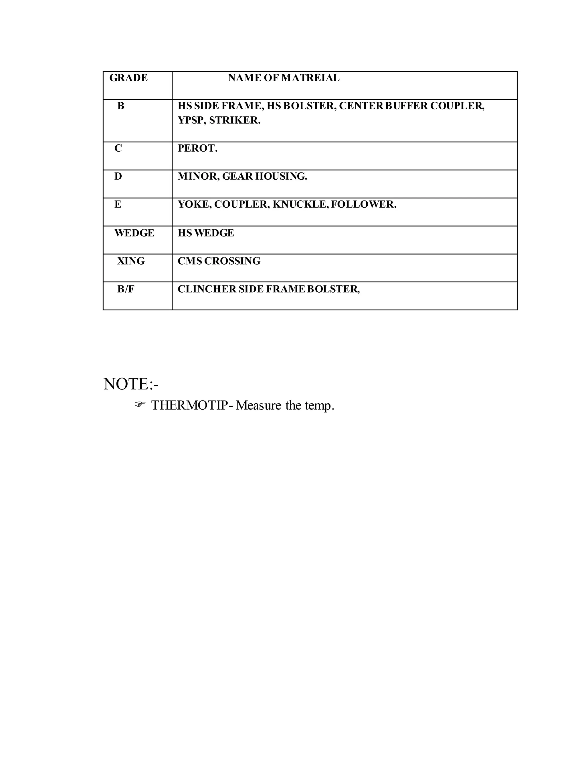
 GRADE OF MATERIAL:
ADJUST CHEMICAL MESURE TEMP.
GRADE NAME OF MATREIAL
B HS SIDE FRAME, HS BOLSTER, CENTERBUFFER COUPLER,
YPSP, STRIKER.
C PEROT.
D MINOR, GEAR HOUSING.
E YOKE, COUPLER, KNUCKLE,FOLLOWER.
WEDGE HS WEDGE
XING CMS CROSSING
B/F CLINCHER SIDE FRAMEBOLSTER,
NOTE:-
 THERMOTIP- Measure the temp.
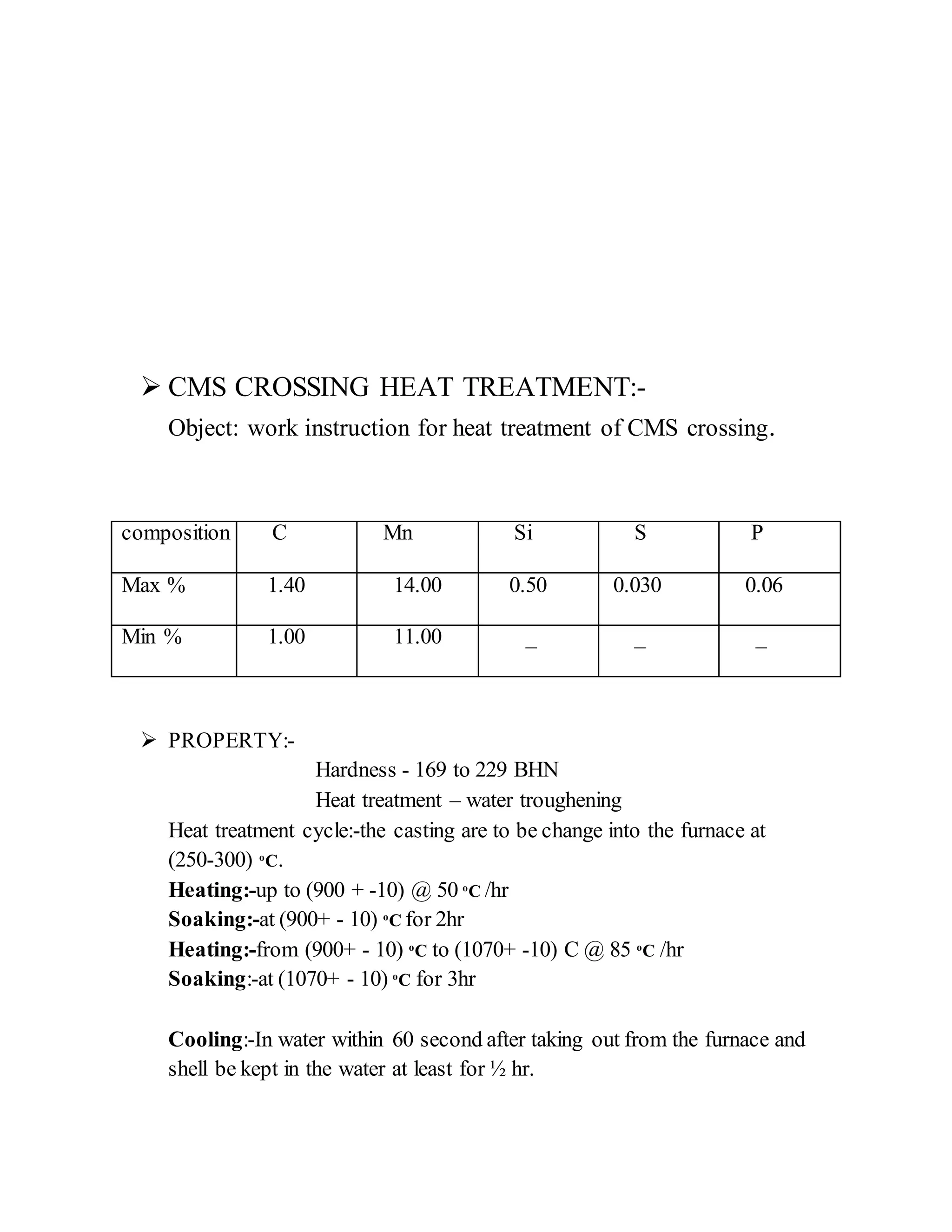
 CMS CROSSING HEAT TREATMENT:-
Object: work instruction for heat treatment of CMS crossing.
composition C Mn Si S P
Max % 1.40 14.00 0.50 0.030 0.06
Min % 1.00 11.00 _ _ _
 PROPERTY:-
Hardness - 169 to 229 BHN
Heat treatment – water troughening
Heat treatment cycle:-the casting are to be change into the furnace at
(250-300) o
C.
Heating:-up to (900 + -10) @ 50 o
C /hr
Soaking:-at (900+ - 10) o
C for 2hr
Heating:-from (900+ - 10) o
C to (1070+ -10) C @ 85 o
C /hr
Soaking:-at (1070+ - 10) o
C for 3hr
Cooling:-In water within 60 second after taking out from the furnace and
shell be kept in the water at least for ½ hr.
Water shall be continuously agitated and circulated so that the temp. does
not excessed 30+ - 10 o
C

More Related Content

What's hot

Refractories in Cupola furnace
Refractories in Cupola furnaceRefractories in Cupola furnace
Refractories in Cupola furnace
عطاءالمنعم اثیل شیخ
 
Casting furnaces
Casting furnacesCasting furnaces
Casting furnaces
Nisarg Thakkar
 
Developments in electric arc furnaces
Developments in electric arc furnacesDevelopments in electric arc furnaces
Developments in electric arc furnaces
Raghav Saxena
 
Melting furnace
Melting furnaceMelting furnace
Melting furnace
sairaagav
 
The arc furnace
The arc furnaceThe arc furnace
The arc furnace
Leonardo ENERGY
 
Industrial furnace manufacturers – Most popular choice for your industrial ap...
Industrial furnace manufacturers – Most popular choice for your industrial ap...Industrial furnace manufacturers – Most popular choice for your industrial ap...
Industrial furnace manufacturers – Most popular choice for your industrial ap...
Shivang Furnace
 
Cupola furnace krishna 9107
Cupola furnace krishna 9107Cupola furnace krishna 9107
Cupola furnace krishna 9107
Digvijaysinh Gohil
 
Vipulesh
VipuleshVipulesh
Industrial Furnace Types
Industrial Furnace TypesIndustrial Furnace Types
Industrial Furnace Types
Vijaya Engineering Works
 
Electric arc furnace
Electric arc furnaceElectric arc furnace
Electric arc furnace
Gulfam Hussain
 
Introduction to Furnace
Introduction to FurnaceIntroduction to Furnace
Introduction to Furnace
Hasnaın Sheıkh
 
Furnace, fuels and fluxes
Furnace, fuels and fluxesFurnace, fuels and fluxes
Furnace, fuels and fluxes
Adesina Joshua
 
Machines and furnaces used in foundry
Machines and furnaces used in foundryMachines and furnaces used in foundry
Machines and furnaces used in foundry
MuhammadFarooq466
 
Design Project, kerala technological university - KTU
Design Project, kerala technological university -  KTU Design Project, kerala technological university -  KTU
Design Project, kerala technological university - KTU
JESTIN JAISON
 

What's hot (20)

Refractories in Cupola furnace
Refractories in Cupola furnaceRefractories in Cupola furnace
Refractories in Cupola furnace
 
Cupola furnace
Cupola furnaceCupola furnace
Cupola furnace
 
Cupola furnaces
Cupola furnacesCupola furnaces
Cupola furnaces
 
Casting furnaces
Casting furnacesCasting furnaces
Casting furnaces
 
Casting Furnaces
Casting FurnacesCasting Furnaces
Casting Furnaces
 
Developments in electric arc furnaces
Developments in electric arc furnacesDevelopments in electric arc furnaces
Developments in electric arc furnaces
 
Reverberatory furnace
Reverberatory furnaceReverberatory furnace
Reverberatory furnace
 
Melting furnace
Melting furnaceMelting furnace
Melting furnace
 
Cupola furnaca
Cupola furnacaCupola furnaca
Cupola furnaca
 
Pit furnace
Pit furnacePit furnace
Pit furnace
 
The arc furnace
The arc furnaceThe arc furnace
The arc furnace
 
Industrial furnace manufacturers – Most popular choice for your industrial ap...
Industrial furnace manufacturers – Most popular choice for your industrial ap...Industrial furnace manufacturers – Most popular choice for your industrial ap...
Industrial furnace manufacturers – Most popular choice for your industrial ap...
 
Cupola furnace krishna 9107
Cupola furnace krishna 9107Cupola furnace krishna 9107
Cupola furnace krishna 9107
 
Vipulesh
VipuleshVipulesh
Vipulesh
 
Industrial Furnace Types
Industrial Furnace TypesIndustrial Furnace Types
Industrial Furnace Types
 
Electric arc furnace
Electric arc furnaceElectric arc furnace
Electric arc furnace
 
Introduction to Furnace
Introduction to FurnaceIntroduction to Furnace
Introduction to Furnace
 
Furnace, fuels and fluxes
Furnace, fuels and fluxesFurnace, fuels and fluxes
Furnace, fuels and fluxes
 
Machines and furnaces used in foundry
Machines and furnaces used in foundryMachines and furnaces used in foundry
Machines and furnaces used in foundry
 
Design Project, kerala technological university - KTU
Design Project, kerala technological university -  KTU Design Project, kerala technological university -  KTU
Design Project, kerala technological university - KTU
 

Similar to anku (Arc Furnance report)

electric arc furnace
electric arc furnaceelectric arc furnace
electric arc furnace
SanjitDhar
 
Plasma arc welding
Plasma arc weldingPlasma arc welding
Plasma arc welding
khalid48261
 
Steel - BUILDING MATERIALS AND CONSTRUCTION)
Steel - BUILDING MATERIALS AND CONSTRUCTION)Steel - BUILDING MATERIALS AND CONSTRUCTION)
Steel - BUILDING MATERIALS AND CONSTRUCTION)
Andhra University
 
MIDHANI diploma
MIDHANI diplomaMIDHANI diploma
MIDHANI diploma
vishnumohan2224
 
Melting furnaces
Melting furnacesMelting furnaces
Melting furnaces
Koushik Kosanam
 
Plasma Arc Machining (Modern Manufacturing Process)
Plasma Arc Machining (Modern Manufacturing Process)Plasma Arc Machining (Modern Manufacturing Process)
Plasma Arc Machining (Modern Manufacturing Process)
Dinesh Panchal
 
Steel manufacturing.ppthhh>jjjjjjjjjjjjjjj
Steel manufacturing.ppthhh>jjjjjjjjjjjjjjjSteel manufacturing.ppthhh>jjjjjjjjjjjjjjj
Steel manufacturing.ppthhh>jjjjjjjjjjjjjjj
teddiyfentaw
 
1.2 resistance and special welding
1.2 resistance and special welding1.2 resistance and special welding
1.2 resistance and special welding
Suren Sirohi
 
Arc furnaces eaf
Arc furnaces eafArc furnaces eaf
Arc furnaces eaf
Jonathan A Pinilla D
 
01 transformer construction
01 transformer construction01 transformer construction
01 transformer construction
Aman Ansari
 
Manufacturing Processes (Arc Welding)
Manufacturing Processes (Arc Welding)Manufacturing Processes (Arc Welding)
Manufacturing Processes (Arc Welding)
Dhrumit Patel
 
ME 12A8 - WELDING TECHNOLOGY for industries.pptx
ME 12A8 - WELDING TECHNOLOGY for industries.pptxME 12A8 - WELDING TECHNOLOGY for industries.pptx
ME 12A8 - WELDING TECHNOLOGY for industries.pptx
RamasamyN4
 
Effect of austemperig on ductile iron
Effect of austemperig on ductile ironEffect of austemperig on ductile iron
Effect of austemperig on ductile iron
Pratik Rathod
 
Blast Furnace Iron Making Process with Construction and Chemical Reactions in...
Blast Furnace Iron Making Process with Construction and Chemical Reactions in...Blast Furnace Iron Making Process with Construction and Chemical Reactions in...
Blast Furnace Iron Making Process with Construction and Chemical Reactions in...
029DevendraKumarSing
 
Plasma Project fourth draft - Mike script
Plasma Project fourth draft - Mike scriptPlasma Project fourth draft - Mike script
Plasma Project fourth draft - Mike scriptMichael Garibaldi
 
Steel Melting Shop (SMS)
Steel Melting Shop (SMS)Steel Melting Shop (SMS)
Steel Melting Shop (SMS)
Gautham Reddy
 
Plasma arc machining
Plasma arc machiningPlasma arc machining
Plasma arc machining
RAJKUMAR Rswagmare
 

Similar to anku (Arc Furnance report) (20)

electric arc furnace
electric arc furnaceelectric arc furnace
electric arc furnace
 
Plasma arc welding
Plasma arc weldingPlasma arc welding
Plasma arc welding
 
Steel - BUILDING MATERIALS AND CONSTRUCTION)
Steel - BUILDING MATERIALS AND CONSTRUCTION)Steel - BUILDING MATERIALS AND CONSTRUCTION)
Steel - BUILDING MATERIALS AND CONSTRUCTION)
 
MIDHANI diploma
MIDHANI diplomaMIDHANI diploma
MIDHANI diploma
 
Melting furnaces
Melting furnacesMelting furnaces
Melting furnaces
 
Steel MAking: Lecture BOS and EAF
Steel MAking: Lecture BOS and EAFSteel MAking: Lecture BOS and EAF
Steel MAking: Lecture BOS and EAF
 
Plasma Arc Machining (Modern Manufacturing Process)
Plasma Arc Machining (Modern Manufacturing Process)Plasma Arc Machining (Modern Manufacturing Process)
Plasma Arc Machining (Modern Manufacturing Process)
 
Steel manufacturing.ppthhh>jjjjjjjjjjjjjjj
Steel manufacturing.ppthhh>jjjjjjjjjjjjjjjSteel manufacturing.ppthhh>jjjjjjjjjjjjjjj
Steel manufacturing.ppthhh>jjjjjjjjjjjjjjj
 
1.2 resistance and special welding
1.2 resistance and special welding1.2 resistance and special welding
1.2 resistance and special welding
 
Arc furnaces eaf
Arc furnaces eafArc furnaces eaf
Arc furnaces eaf
 
01 transformer construction
01 transformer construction01 transformer construction
01 transformer construction
 
Manufacturing Processes (Arc Welding)
Manufacturing Processes (Arc Welding)Manufacturing Processes (Arc Welding)
Manufacturing Processes (Arc Welding)
 
ME 12A8 - WELDING TECHNOLOGY for industries.pptx
ME 12A8 - WELDING TECHNOLOGY for industries.pptxME 12A8 - WELDING TECHNOLOGY for industries.pptx
ME 12A8 - WELDING TECHNOLOGY for industries.pptx
 
Effect of austemperig on ductile iron
Effect of austemperig on ductile ironEffect of austemperig on ductile iron
Effect of austemperig on ductile iron
 
Blast Furnace Iron Making Process with Construction and Chemical Reactions in...
Blast Furnace Iron Making Process with Construction and Chemical Reactions in...Blast Furnace Iron Making Process with Construction and Chemical Reactions in...
Blast Furnace Iron Making Process with Construction and Chemical Reactions in...
 
Plasma Project fourth draft - Mike script
Plasma Project fourth draft - Mike scriptPlasma Project fourth draft - Mike script
Plasma Project fourth draft - Mike script
 
Steel Melting Shop (SMS)
Steel Melting Shop (SMS)Steel Melting Shop (SMS)
Steel Melting Shop (SMS)
 
Faisal
FaisalFaisal
Faisal
 
Plasma arc machining
Plasma arc machiningPlasma arc machining
Plasma arc machining
 
STEEL.pptx
STEEL.pptxSTEEL.pptx
STEEL.pptx
 

anku (Arc Furnance report)

  • 1. REPORT (ELECTRIC AEC FURNACE, MELTING, HEAT TREATMENT) NAME: ANKU KUMAR PANDEY INDUSTRY NAME: - COLLEGE NAME: SS COLLEGE OF ENGINEERING, TITAGARG WAGON LTD.  What is a furnace:- ▪ A furnace is essentially a thermal enclosure and is employed to process raw materials at high temperatures both in solid state and liquid state. ▪ Several industries like iron and steel making, nonferrous metals production, glass making, manufacturing, ceramic processing, calcination in cement production etc. a) To utilize heat efficiently so that losses are minimum, and b) To handle the different phases (solid, liquid or gaseous) moving at different velocities for different times and temperatures such that erosion and corrosion of the refractory are minimum.  What are the components of a furnace:- i Source of energy a) Fossil fuel: For fossil fuel one requires burner for efficient mixing of fuel and air. Arrangement of burner is important. b) Electric energy: Resistance heating, induction heating or arc heating. c) Chemical energy: Exothermic reactions ii. Suitable refractory material: Refractory design is important. Thermal enclosure of the furnace is designed and constructed keeping in view the requirements.
  • 2. For example refractory facing the thermal enclosure must have high refractoriness, chemically inert etc. Whereas refractory facing the surrounding must have low thermal conductivity to minimize heat losses. iii. Heat exchanger: Heat exchanger is becoming now as part of the fossil fuel fired furnaces in order to recover and reuse the heat of POC. Heat of POC can be used either external to furnace by installing a heat exchanger or internally by recirculation the POC within the furnace.  Type of Electric furnaces: ▪ In principle an electric arc is formed between the electrode and the metallic charge and charge is heated from the arc radiation. ▪ Electric arc furnaces are of two type (a) alternating current and (b) direct current. In alternating current, furnace operates by means of electric current flowing from one electrode of three to another through the metallic charge. ▪ In direct current, the current flows from carbon electrode, which acts as cathode, to an anode embedded in the bottom of the furnace.  Construction of AC Electric Arc Furnace ▪ The furnace consists of a steel shell, lined with suitable refractory materials and is mounted on the tilting mechanism. ▪ The shell thickness is around 0.005 times the shell diameter. Three electrodes enter through the roof. ▪ The hood may be swung away for charging. Heat is generated by the hot area formed between the electrodes and the charge. Hearth ▪ The hearth contains metal and slag. ▪ The hearth lining consists of backing lining and working lining.
  • 3. ▪ The backing lining is few layers of high fired magnesite bricks on which working lining is rammed with either dolomite or magnesite mass. ▪ Permeable blocks or porous refractory elements are introduced through the bottom to inject inert gas for stirring. ▪ The EAF steel bath is shallow; the aspect ratio of the bath is around 0.2 to 0.22. Roof ▪ The roof isexposedtomore heatthan otherfurnace elements. ▪ Its liningisalsosubjectedtoradiantheatreflectedfromthe wallsandslag. ▪ Highaluminabricksand magnesite - chromite bricksare usedforroof lining. ▪ The roof liningiswatercooledwhichincreasesthe lifeof refractoryliningtoat least10-20 times more than withoutwatercooling. Electrode ▪ A typical alternatingcurrentoperatedEAFhasthree electrodes. ▪ Electrodesare roundinsection,andtypicallyinsegmentswiththreadedcoupling,sothatas the electrodeswear,new segmentscanbe added. ▪ Graphite electrodesare preferredovercarbonelectrodesbecauseof betterelectrical conductivity. ▪ The electrodesare automaticallyraisedandloweredbyapositioningsystem.  Electrode consumption depends on • Oxidation of the surface of the electrode • Mechanical losses due to fracture • Dissolution in slag during carbon boil ▪ The diameter of the electrode should correspond to the current supplied; if current density is excessively high, electrodes will be heated and oxidized vigorously. ▪ The electrode current could vary from 12 to 16A⁄cm2 for 400 to 600 m electrode diameter. Larger electrode diameter increases electric energy consumption. ▪ The electrodes are positioned at apexes of an equilateral triangle. ▪ The diameter of the circle passing through the centers of electrodes is called the diameter of the electrode spacing. ▪ If the electrodes are placed close to each other and far from furnace walls, the charge at the furnace banks will be heated belatedly.
  • 4. ▪ With large spacing diameter, electric arcs will burn near the walls, which will result in rapid wear of the lining. ▪ The electrode spacing diameter for the bath diameter could be 0.45 for small furnaces, 0.35 for medium- sized and large furnaces, and still lower for super- powerful furnaces. For a bath diameter of 5560 mm of a 100 ton furnace the electrode spacing diameter would be 0.35 × 5560 = 1900mm. Side walls ▪ The side walls refractory materials should be able to withstand thermal shock and corrosive action of slag. ▪ Hot spot is formed on the side walls due to the radiation from arc flames, reflected from bath surface during power input. ▪ The side wall is lined with magnesite or dolomite or chrome magnesite bricks up to the slag line. ▪ The side wall thickness is usually 450 to 500mm for 10 to 50 ton furnaces and 550 to 650mm for 100 to 200 ton furnaces. Transformer power: ▪ Electric furnaces are powerful consumers of electric energy. ▪ The operating voltage of a furnace is 100-800V and the current may reach several thousand amperes. ▪ The furnace transformer high voltage energy into low voltage.  The melting process consists of two periods: Melt down and refining period. ▪ In melt down period higher electric energy is required as compared with the refining period. ▪ In small furnaces, the power consumption for melting is about 600kWh⁄ton and it falls to 450kWh⁄ton in big furnaces. ▪ Additional 150 to 400kWh⁄ton power is required during refining depending on the practice. ▪ Large transformers are required to run electric arc furnaces. ▪ During melting more power is required than during refining. The transformer capacity is designed to suit melting requirements. ▪ The capacity of the transformer is usually 470- 650 KVA per ton of furnace capacity.
  • 5. ▪ In terms of hearth area, the transformer capacity is in the range of 750-900 KVA per square meter Charging materials: ▪ Steel scrap is the principle raw material. ▪ It may constitute 60 to 80% of the charge. In some practices sponge iron and or pig iron is also used for chemical balance. ▪ In basic furnaces slag formers like limestone, fluorspar, sand, and quartzite are used to form a slag to refine the metal. ▪ For decarburization oxygen lancing is used. Iron ore is also added. Ferro-manganese, ferrosilicon or aluminium are used for de oxidation. ▪ To produce alloy steels, alloying elements are added. Arc Furnaces process ▪ It consists of charging, melt down period and refining. ▪ The large baskets containing heavy and light scrap are preheated through the exit gas. ▪ Burnt lime and spar are added to help early slag formation. Iron one or mill scale may also be added if refining is required during melt- down period. ▪ The roof is swung off the furnace, and the furnace is charged. Some furnaces are equipped with continuous charging. ▪ Hot metal is also charged as per the requirement. ▪ In the meltdown period, electrodes are lowered and bored into the scrap. ▪ Lower voltages are selected in order to protect the roof and walls from excessive heat and damage from the arcs. ▪ Once the arc is shielded by scrap, voltage is increased to form molten metal pool to reduce the meltdown period. ▪ During meltdown period, silicon, manganese and carbon oxidizes. ▪ Also oxidizing and limy slag is produces which promotes as well. Melt- down time depends on • Arc conditions: larger arc requires lower current and lower heat losses • Deep or shallow bath: deep bath shortens the meltdown period. ▪ Refining continues even during melting. Removal of phosphorus must be complete before the rise in temperature and carbon boil.
  • 6. ▪ The single oxidizing slag practice is employed when removal of sulphar is not required. ▪ When both P and S are required to be removed double slag practice is used. ▪ In double slag practice, oxidizing slag is removed and reducing slag is formed after de oxidation with ferrosilicon or ferromanganese or aluminum. ▪ Reducing slag helps to avoid loss SMS (STEEL MELTING SHOP) GRADE SMS CYCLE TSL(GRADE) %C %Mn %Si %S %P %Mo %Ni %Cr TSL-01 (GR-B) 0.20/0.30 0.70/0.90 0.40/0.50 0.035 MAX TSL-02 (GR-C) 0.25/0.30 1.40/1.85 0.60/0.90 0.030 MAX TSL-04 (GR-D) 0.30/0.35 0.70/0.95 0.60/0.90 0.035 MAX TSL-03 (GR-E) 0.28/0.32 0.70/0.90 0.40/0.60 0.030 MAX 0.15/0.25 0.50/0.65 0.5/0.8 TSL-08 (WEDGE) 1.00/1.40 10.0/14.0 1.00 MAX 0.03 MAX 0.060 MAX TSL-10 (Xing) 1.00/1.40 11.0/14.0 0.50 MAX 0.03 MAX 0.06 MAX TSL-11 (B.F) 0.23/0.25 0.70/0.90 0.40/0.50 0.025 MAX 0.025 MAX 0.15/0.20 0.30/0.40 0.20/0.30 FETTING & REPAIRING CHECK ELECTRODES
  • 8.  Working step:- 1. FETTING: check out the condition and fettle the furnace with fettling material in the red hot condition of the furnace after each heat. 2. ELECTODE ADJUSTMENT: clean the electrode with compressed air and adjust the length. 3. CHARGING: charge the furnace following the standard operating practice for different grades. 4. MELTING: after charging, close the roof and ensure that the amp set and transformer oil pump are put on. Switch on the furnace and operate the panel board. 5. In all the melt condition and addition of around 10 shovels of lime stone, rack the bath and then take one sample for analyzing the chemistry by spectrometer. 6. OXIDATION: Make the melt down slag by lime stone boil or by tilting the furnace to the maximum possible extent. Add 2 to 3 shovel of fluorspar, which will make the slag free running 7. Make new slag by addition two 15 to 20 shovels of limestone and start adding iron ore as per requirement to create high oxidation atmosphere. Rake the bath at some interval and ensure that no set metal is left on the bottom of the furnace. 8. Boil the bath to reach the required chemistry level. 9. Take out one sample for analyzing the chemistry by spectrometry and ensure that required chemistry level after oxidation is reached. Skim off the slag to the maximum possible extent.  GRADE OF MATERIAL: ADJUST CHEMICAL MESURE TEMP.
  • 9. GRADE NAME OF MATREIAL B HS SIDE FRAME, HS BOLSTER, CENTERBUFFER COUPLER, YPSP, STRIKER. C PEROT. D MINOR, GEAR HOUSING. E YOKE, COUPLER, KNUCKLE,FOLLOWER. WEDGE HS WEDGE XING CMS CROSSING B/F CLINCHER SIDE FRAMEBOLSTER, NOTE:-  THERMOTIP- Measure the temp.
  • 10.  CMS CROSSING HEAT TREATMENT:- Object: work instruction for heat treatment of CMS crossing. composition C Mn Si S P Max % 1.40 14.00 0.50 0.030 0.06 Min % 1.00 11.00 _ _ _  PROPERTY:- Hardness - 169 to 229 BHN Heat treatment – water troughening Heat treatment cycle:-the casting are to be change into the furnace at (250-300) o C. Heating:-up to (900 + -10) @ 50 o C /hr Soaking:-at (900+ - 10) o C for 2hr Heating:-from (900+ - 10) o C to (1070+ -10) C @ 85 o C /hr Soaking:-at (1070+ - 10) o C for 3hr Cooling:-In water within 60 second after taking out from the furnace and shell be kept in the water at least for ½ hr.
  • 11. Water shall be continuously agitated and circulated so that the temp. does not excessed 30+ - 10 o C