Download free for 30 days
Sign in
Upload
Language (EN)
Support
Business
Mobile
Social Media
Marketing
Technology
Art & Photos
Career
Design
Education
Presentations & Public Speaking
Government & Nonprofit
Healthcare
Internet
Law
Leadership & Management
Automotive
Engineering
Software
Recruiting & HR
Retail
Sales
Services
Science
Small Business & Entrepreneurship
Food
Environment
Economy & Finance
Data & Analytics
Investor Relations
Sports
Spiritual
News & Politics
Travel
Self Improvement
Real Estate
Entertainment & Humor
Health & Medicine
Devices & Hardware
Lifestyle
Change Language
Language
English
Español
Português
Français
Deutsche
Cancel
Save
EN
Uploaded by
Leslie Munday
40 views
Analysis Through Pictures Introduction.pdf
The introduction to "Analysis Through Pictures' by Leslie Munday
Engineering
◦
Related topics:
Process Improvement
•
Business Model.
•
Data Modeling Techniques
•
Use Cases
•
Read more
0
Save
Share
Embed
Embed presentation
Download
Download to read offline
1
/ 31
2
/ 31
3
/ 31
4
/ 31
5
/ 31
6
/ 31
7
/ 31
8
/ 31
9
/ 31
10
/ 31
11
/ 31
12
/ 31
13
/ 31
14
/ 31
15
/ 31
16
/ 31
17
/ 31
18
/ 31
19
/ 31
20
/ 31
21
/ 31
22
/ 31
23
/ 31
24
/ 31
25
/ 31
26
/ 31
27
/ 31
28
/ 31
29
/ 31
30
/ 31
31
/ 31
More Related Content
PPT
Analysis modeling & scenario based modeling
by
Benazir Fathima
ODP
BIS09 Application Development - III
by
Prithwis Mukerjee
ZIP
Unified Process
by
guy_davis
PPTX
OOAD U1.pptx
by
anguraju1
PDF
Requirement analysis and UML modelling in Software engineering
by
snehalkulkarni74
PPT
Analysis-Models jjjkkkkjgffffffttui3k3k3j3n
by
mhuzaifasultan8
DOCX
Business Analyst
by
Yaswanth Babu Gummadivelli
PPT
Kelis king - requirements analysis and the unified process
by
KelisKing
Analysis modeling & scenario based modeling
by
Benazir Fathima
BIS09 Application Development - III
by
Prithwis Mukerjee
Unified Process
by
guy_davis
OOAD U1.pptx
by
anguraju1
Requirement analysis and UML modelling in Software engineering
by
snehalkulkarni74
Analysis-Models jjjkkkkjgffffffttui3k3k3j3n
by
mhuzaifasultan8
Business Analyst
by
Yaswanth Babu Gummadivelli
Kelis king - requirements analysis and the unified process
by
KelisKing
Similar to Analysis Through Pictures Introduction.pdf
PPTX
2 L1 - Identifying Use Cases - Copy.pptx
by
chandunara02
PPTX
SE- Lec 3.pptx related to he tech field in it
by
afaizajamil341
PPT
OO Development 5 - Analysis
by
Randy Connolly
PPT
PM Symposium RUP UC Realization
by
Terry Startzel, MS, PMP, SCPM, CSM
PPT
Usecase
by
nazeer pasha
PDF
Requirement analysis with use case
by
Rapeepan Thawornwanchai
PPT
RRC Requirements and Use Cases
by
Terry Startzel, MS, PMP, SCPM, CSM
PPTX
Bussiness analyst training in india
by
united global soft
PPT
Ch05
by
蕭美蓮
PDF
Workshop on Basics of Software Engineering (DFD, UML and Project Culture)
by
Dr Sukhpal Singh Gill
PDF
Building an Information System
by
Jo Balucanag - Bitonio
PDF
Object oriented analysis and design unit- iii
by
Shri Shankaracharya College, Bhilai,Junwani
PPTX
Requirement engineering.pptx power point
by
Coderkids
PPTX
Software Engineering-II Lecture No. 1 basics .pptx
by
UbaidullahJan6
DOC
Good Practices For Developing User Requirements
by
nkaur
PPTX
Use Case Analysis and Diagramming
by
Ornella Dunn
PPT
Ppt ooad ooad3unit
by
ramyalaksha
PDF
data modelling concepts.pdf software engineeringre
by
rramya31
PPS
04 ooad uml-04
by
Niit Care
PDF
Non-functional requirements
by
Rohela Raouf
2 L1 - Identifying Use Cases - Copy.pptx
by
chandunara02
SE- Lec 3.pptx related to he tech field in it
by
afaizajamil341
OO Development 5 - Analysis
by
Randy Connolly
PM Symposium RUP UC Realization
by
Terry Startzel, MS, PMP, SCPM, CSM
Usecase
by
nazeer pasha
Requirement analysis with use case
by
Rapeepan Thawornwanchai
RRC Requirements and Use Cases
by
Terry Startzel, MS, PMP, SCPM, CSM
Bussiness analyst training in india
by
united global soft
Ch05
by
蕭美蓮
Workshop on Basics of Software Engineering (DFD, UML and Project Culture)
by
Dr Sukhpal Singh Gill
Building an Information System
by
Jo Balucanag - Bitonio
Object oriented analysis and design unit- iii
by
Shri Shankaracharya College, Bhilai,Junwani
Requirement engineering.pptx power point
by
Coderkids
Software Engineering-II Lecture No. 1 basics .pptx
by
UbaidullahJan6
Good Practices For Developing User Requirements
by
nkaur
Use Case Analysis and Diagramming
by
Ornella Dunn
Ppt ooad ooad3unit
by
ramyalaksha
data modelling concepts.pdf software engineeringre
by
rramya31
04 ooad uml-04
by
Niit Care
Non-functional requirements
by
Rohela Raouf
More from Leslie Munday
PPTX
Presentation About My BABOK Analysis.pptx
by
Leslie Munday
PDF
BABOK Artifacts Mapped To Tasks And Elements.pdf
by
Leslie Munday
PDF
Overview of the BABOK Analysis Model.pdf
by
Leslie Munday
PDF
BABOK Suggestions And Recommendations.pdf
by
Leslie Munday
PDF
Quality With Agile Process Book Overview.pdf
by
Leslie Munday
PPTX
Using Agile In A Quality Driven Environment
by
Leslie Munday
PPTX
Models vs Diagrams
by
Leslie Munday
PPT
Requirements and Traceability With Pictures
by
Leslie Munday
PPT
Using Styles and Properties with MS Word
by
Leslie Munday
PPT
Use Case and Activity Diagrams Modeling Notation
by
Leslie Munday
PPTX
An Analysis Of A Jigsaw Puzzle
by
Leslie Munday
PPT
Realizing an Application Use Case
by
Leslie Munday
PPT
How to Complete a Use Case Templlate with MS Word
by
Leslie Munday
PPTX
Create A Use Case Document with ReqPro
by
Leslie Munday
PPTX
An Analysis of the BABOK
by
Leslie Munday
PPTX
Requirements management and traceability for IIBA
by
Leslie Munday
PPTX
Analysis Of A Shopping Expedition Part II
by
Leslie Munday
PPT
Use Case and Activity Diagrams Modeling Notation
by
Leslie Munday
PPT
Working With Styles And Properties
by
Leslie Munday
PPT
Administrating Req Pro
by
Leslie Munday
Presentation About My BABOK Analysis.pptx
by
Leslie Munday
BABOK Artifacts Mapped To Tasks And Elements.pdf
by
Leslie Munday
Overview of the BABOK Analysis Model.pdf
by
Leslie Munday
BABOK Suggestions And Recommendations.pdf
by
Leslie Munday
Quality With Agile Process Book Overview.pdf
by
Leslie Munday
Using Agile In A Quality Driven Environment
by
Leslie Munday
Models vs Diagrams
by
Leslie Munday
Requirements and Traceability With Pictures
by
Leslie Munday
Using Styles and Properties with MS Word
by
Leslie Munday
Use Case and Activity Diagrams Modeling Notation
by
Leslie Munday
An Analysis Of A Jigsaw Puzzle
by
Leslie Munday
Realizing an Application Use Case
by
Leslie Munday
How to Complete a Use Case Templlate with MS Word
by
Leslie Munday
Create A Use Case Document with ReqPro
by
Leslie Munday
An Analysis of the BABOK
by
Leslie Munday
Requirements management and traceability for IIBA
by
Leslie Munday
Analysis Of A Shopping Expedition Part II
by
Leslie Munday
Use Case and Activity Diagrams Modeling Notation
by
Leslie Munday
Working With Styles And Properties
by
Leslie Munday
Administrating Req Pro
by
Leslie Munday
Recently uploaded
PPTX
Fake News Detection System | Plagiarism detection
by
surajkanojiya13
PPTX
UNIT 2 - Electronics Device - EC25C01 - PN Junction Diodes
by
Mathavan N
PPTX
Unit 3_statistical methods in data science.pptx
by
Vidyaranichougule
PDF
Chris Elwell Woburn - An Experienced IT Executive
by
Chris Elwell Woburn
PPTX
Electronics Device - EC25C01 - Semiconductor: Types, Conductivity,
by
Mathavan N
PDF
Decision-Support-Systems-and-Decision-Making-Processes.pdf
by
PatankarNikhil
PDF
0.39 Inch Micro-OLED Display 1024×768 XGA Panel Silicon OLED
by
Syluxdisplay
PDF
CME397 SURFACE ENGINEERING UNIT 1 FULL NOTES
by
karthi keyan
PPTX
Speech to Text with Tone Correction.pptx
by
surajkanojiya13
PDF
Manual de instalacion de notifire NFS320
by
MarcoPolitoPerez
PPTX
Lubrication Neglect Causes More Downtime Than AI Ever Will Why Maintenance Fu...
by
MaintWiz Technologies Private Limited
PPTX
Origin of Soil and Grain Size with Introduction and explanation
by
MahmoodKhalid11
PDF
Computer Graphics Fundamentals (v0p1) - DannyJiang
by
Danny Jiang
PPTX
SketchUp Pro 2026 – Advanced 3D Modeling Software
by
Hoka Moka
PDF
Infinite Sequence and Series: It Includes basic Sequence and Series
by
DynamicDomain1
PPTX
Integrating Azure Event Services_ Event Grid, Event Hubs, and Service Bus.pptx
by
ADITYASHARMA423788
PDF
A Newbie’s Journey: Hidden MySQL Pain Points That Vitess Quietly Solves
by
Igor Donchovski
PDF
Feedback and Network Architectures - Dynamics and Memory
by
Adri Jovin
PDF
comprehensive analysis of cross-chain bridges in the DeFi - Garima Singh
by
Garima Singh
PPTX
Basin Design Service, LLC Introduction Presentation
by
Hubie Fix
Fake News Detection System | Plagiarism detection
by
surajkanojiya13
UNIT 2 - Electronics Device - EC25C01 - PN Junction Diodes
by
Mathavan N
Unit 3_statistical methods in data science.pptx
by
Vidyaranichougule
Chris Elwell Woburn - An Experienced IT Executive
by
Chris Elwell Woburn
Electronics Device - EC25C01 - Semiconductor: Types, Conductivity,
by
Mathavan N
Decision-Support-Systems-and-Decision-Making-Processes.pdf
by
PatankarNikhil
0.39 Inch Micro-OLED Display 1024×768 XGA Panel Silicon OLED
by
Syluxdisplay
CME397 SURFACE ENGINEERING UNIT 1 FULL NOTES
by
karthi keyan
Speech to Text with Tone Correction.pptx
by
surajkanojiya13
Manual de instalacion de notifire NFS320
by
MarcoPolitoPerez
Lubrication Neglect Causes More Downtime Than AI Ever Will Why Maintenance Fu...
by
MaintWiz Technologies Private Limited
Origin of Soil and Grain Size with Introduction and explanation
by
MahmoodKhalid11
Computer Graphics Fundamentals (v0p1) - DannyJiang
by
Danny Jiang
SketchUp Pro 2026 – Advanced 3D Modeling Software
by
Hoka Moka
Infinite Sequence and Series: It Includes basic Sequence and Series
by
DynamicDomain1
Integrating Azure Event Services_ Event Grid, Event Hubs, and Service Bus.pptx
by
ADITYASHARMA423788
A Newbie’s Journey: Hidden MySQL Pain Points That Vitess Quietly Solves
by
Igor Donchovski
Feedback and Network Architectures - Dynamics and Memory
by
Adri Jovin
comprehensive analysis of cross-chain bridges in the DeFi - Garima Singh
by
Garima Singh
Basin Design Service, LLC Introduction Presentation
by
Hubie Fix
Analysis Through Pictures Introduction.pdf
1.
Intentionally Left Blank For Autographs
2.
Analysis Through Pictures
Version 3.0 © 2011 Leslie Munday Page 1 Introduction This work describes a requirements lifecycle based on the Rational Unified Process (RUP) framework1 , from business modeling through to analysis and design. The RUP is a framework, not a development method. It contains many, if not most, of the best practices for software development. It describes the Software Development Life Cycle (SDLC) in terms of Actors, Artifacts and Activities. These are grouped into 9 disciplines (some included in multiple disciplines). There are approximately 30 actors, around 100 artifacts and even more activities described by RUP in total. No SDLC could adopt the whole framework and expect to accomplish an efficient method for developing software. RUP uses the Unified Modeling Language (UML) as its basis for artifact development. Like RUP, UML contains every notation that every developer could need for modeling within a SDLC. No development effort would utilize the complete UML notation. In fact UML has many more redundancies than RUP, some of them duplicates and some just do not work together. With all these tools available for software development, how does one sift through them all and pull out a subset that is appropriate for their particular situation? This work describes a subset of RUP and UML, that when combined together prove an effective method for software development in almost any situation. It makes use of the most useful development practices and the most common UML notations, but only to the extent that these activities and notation are sufficient without any duplication or ambiguity. I.e. it describes a minimum set of tools that any software analyst needs, while at the same time allowing the analysis of just about any type of development project involving computer systems. 1 IBM Rational will tell you that no-one in their right mind should attempt to use every recommendation within the RUP on a single project. Nor does RUP encompass all the needs of most projects. Customization is always necessary.
3.
Analysis Through Pictures
Version 3.0 © 2011 Leslie Munday Page 2 Purpose The purpose of this work is to describe an implementable use case based approach for developing the requirements for a project. It is not going to describe requirements artifacts and then not explain their purpose or where they fit into the project lifecycle2 . Every artifact that is described is the result of a step in the process that produces something for a specific stakeholder. Other software development processes may provide a framework for working with application requirements, but are rarely specific about the actual steps that an analyst could follow in order to produce a complete set of requirements artifacts. This process specifies the exact steps that the analyst could follow, with examples, and the format of the artifacts that are produced from those steps. If the style of writing reads like a set of instructions for performing analysis using a particular method, that may be because much of this work is drawn from training material that is available from my web site. It is not necessary to follow the instructions to the letter, but if one does modify a guideline, or introduce other rules for working with analysis, the reader must be aware that the guidelines between different parts of the model are inter-related. Changes to one part of the process will often have implications on the format of the model at other stages in the process. The examples are based upon real-world commercial business systems and the result of the process is a complete3 analysis model of a computer system. Audience This document is written for requirements analysts and systems or business/systems analysts who are looking for a specific set of requirements development processes that will work for them in order to deliver an appropriate analysis model. In particular, any process engineer 2 This is a common problem I have experienced with software modeling books. Lots of examples, but no guidelines as to how to fit the examples together in a full requirements lifecycle. 3 Complete as much as I can verify with MS Visio.
4.
Analysis Through Pictures
Version 3.0 © 2011 Leslie Munday Page 3 who would be interested in a customized process that follows the best practices of the RUP4 . What this work does not include: The purpose of use cases and how they are used by the business or an IT department. The reader is expected to be experienced with extracting requirements from stakeholders and documenting their details with use cases. It helps if the reader has a basic understanding of the difference between a business use case and a system (or application) use case. Class diagrams and normalizing entity relationship diagrams The reader should have experience with entity relationship modeling, and have a basic understanding of class attributes and operations. It also helps to understand class relationships, such as aggregation, composition and inheritance. Managing a Software Development Life Cycle The work in this book should be able to be incorporated into most SDLCs that employ requirements analysis. It does not discuss the activities of a project or program manager. Notation This work is not intended to make recommendations about specific notation used within the UML diagrams. Whether using underscores, capitalized words or Hungarian notation, etc, is normally defined by development standards. The only recommendation is that the notations on the diagrams should be consistent. For example, if using capitalized words to describe classes, then whenever a class is referenced, the name in the reference should also be capitalized. Overview The material starts with some practices for working with MS Office in a requirements environment. It then goes on to give an overview of the ideas 4 RUP 2003 best practices; these have changed in later versions – not necessarily for the better, IMO.
5.
Analysis Through Pictures
Version 3.0 © 2011 Leslie Munday Page 4 behind the work; talks about use cases; describes a process for developing use case models; project glossaries; the lifecycle of a use case; use case storyboards; a process for object-oriented analysis and modeling the world in states. The work is in 2 parts (although the chapters are interlaced, and there is no obvious place of separation): The first part is a series of best practices for working with requirements, tools and use cases. The second part uses the best practices to model a restaurant management system from a business vision through to a complete set of software requirements. The process is neither Waterfall, nor Agile. Being use case based it may be deployed in either environment. The description of the process is sequential. That is it starts with the business vision, and walks you through the steps to produce a set of software requirements, but there is no reason why all steps need to be completed in sequence. To adopt the process in an iterative SLDC, one simply walks each use case through the complete process in turn. To adopt the process into a waterfall SDLC, one develops the complete set of use cases, and adds the required documents and gates at the appropriate places in the process. This process is mainly concerned with the processes and artifacts that an Analyst is interested in. Project management guidelines can be added at the appropriate places. Definitions, Acronyms, and Abbreviations See Appendix A for a complete list of technical terms used within this text. Some terms that are useful in understanding the overall material are: The differences between Project, Product and Program. In this document they are used as follows: Project – is a development effort that satisfies the needs of the business. A project may encompass several business areas, each with their own
6.
Analysis Through Pictures
Version 3.0 © 2011 Leslie Munday Page 5 specific needs. These needs are implemented by one or more enterprise- wide systems. Product – is an application or series of applications that reside on a system. A single project may impact several products. Program – is the complete set of products that are impacted by a project. Therefore; a Project Manager is responsible for the successful delivery of a project to the business. A program manger is responsible for the successful implementation of a project. Whereas a product manager is responsible for all project implementations that impact the applications under their responsibility. In addition you will need to understand how this book differentiates between a system and an application. Application – is the software that automates a process or processes that satisfy business needs. System – is the hardware and software that satisfies business needs. A system may contain several applications, but a software application can only reside within 1 system5 . Contents The contents of this document are: Precursor Describes how MS Office is being used by the examples contained in this work. Chapter 1 Is an overview of the major problems that the process is attempting to solve. This section introduces the reader to some best practices for helping to solve the major problems that an analyst might encounter with software requirements management. Chapter 2 Is all about use cases. The types of use case described, are business use cases (BUCs) and application use cases 5 This rule is important when it comes to building use cases – please make sure that you understand its implications.
7.
Analysis Through Pictures
Version 3.0 © 2011 Leslie Munday Page 6 (AUCs). This chapter identifies the difference between the 2 types of use case and introduces templates for writing use cases Chapter 3 Defines a notation for modeling use cases with use case diagrams. Chapter 4 Contains a notation for detailing activity diagrams. It describes how UML activity diagrams may be used to capture the different components of a BUC and an AUC. Chapter 5 Contains guidelines for modeling classes with a logical model. Chapter 6 Introduces the reader to states. In particular it describes a notation for modeling classes with State Transition diagrams Chapter 7 Contains examples of Business and Application use cases. Chapter 8 Contains ideas for organizing artifacts of an iterative development process. In particular it describes a method for organizing a requirements repository such that software applications may be developed in parallel. Chapter 9 Describes best practices for managing a glossary. The importance of maintaining a glossary for your project, what the glossary comprises, tools for maintaining the glossary and how to use the glossary in conjunction with documentation. Chapter 10 Describes the Business Vision in terms of a vision template, the contents of the vision, its purpose and how it is used on a project. Chapter 11 Contains an example of a Business Model, including business architecture rules and business use cases. Chapter 12 Describes how to progress through the lifecycle from a BUC model to an AUC model. Chapter 13 Contains guidelines for producing a class (logical) model from the details of the AUC.
8.
Analysis Through Pictures
Version 3.0 © 2011 Leslie Munday Page 7 Chapter 14 Describes how to analyze the logical model with state transition diagrams. Chapter 15 Introduces use case realizations. It describes how to realize AUCs with sequence diagrams. Chapter 16 Concludes requirements capture with some best practices for writing software requirements. It includes guidelines for detailing the requirements that were captured by the AUC model. Chapter 17 Describes Use Case storyboards. These describe use cases in terms of a user interface. They are used for getting feedback about the user interface functionality associated with the use cases. Chapter 18 Describes the contents of a requirements management plan; It contains Ideas for managing requirements and traceability using a document management tool, such as MOSS. Chapter 19 Is a summary. It includes an overview of the complete process. Appendix A Contains a glossary of terms used within this book. Appendix B This chapter contains a complete analysis solution to the Automated Menu System project. From a business Vision, through to a logical model containing operations in the form of application requirements.
9.
Analysis Through Pictures
Version 3.0 © 2011 Leslie Munday Page 8 Foreword I have been reading books about analysis and taking analysis training classes, since 1988. These include books by Tom DeMarco, Ward and Mellor, Yourdon and of course the Unified Software Development Process by the Three Amigos. I have also taken structured analysis training from several experts in the field, but only one book has left me with a sense that I learned a process along with the notation. That is; Object Lifecycles (Modeling the world in states) by Sally Shlaer and Stephen Mellor. This book was published in the late 1980s. Other books on requirements, to cite a common analogy; describe the details of the trees, bushes and undergrowth, but have always left me with a sense that I had no picture of what the wood looks like. That is to say that they describe analysis diagrams and best practices for creating them, but left me without the knowledge of ‘how to I use these on my current project?’ You will find that much of this material is based upon Sally and Stephen’s work, but since the book was published before the worldwide adoption of use cases, much of this material is also outside of the scope of their book, and based on my own experiences. Personal History My career ambitions have been aimed at software development from an early age. I remember visiting a local government computer establishment when I was around 9, and being fascinated with the machinery, the tape drives, the disk-drives and having to wear hair nets, a plastic coat and coverings over my shoes. I was hooked and would jump at any opportunity to see a working computer. My first chance to study these fascinating machines came at the age of 14, when my school introduced ‘Computer Studies’ as a new student course6 . My development path through learning computers started with writing 6 I like to believe that I was first in line to sign up.
10.
Analysis Through Pictures
Version 3.0 © 2011 Leslie Munday Page 9 pseudo assembler code onto programming sheets, then coding BASIC onto punch cards. When I left school I had been allowed to enter commands to a remote computer directly through a teletype, and get an almost immediate response (sometimes within seconds). When I graduated I worked at a school that wanted me to teach Mathematics, but allowed me to also teach Computer Science as a secondary subject. It was here that I had my first access to a PC; the Commodore Pet. The vast majority of my early programming experience was with assembler, using a direct terminal or sometimes punched tape and other times by entering the machine code directly into memory via a series of switches. After 5 years of programming, I took a job writing requirements documentation from which external subcontractors would develop the code. This was my first experience with requirements analysis and the first time that I needed to understand a ‘real’ SDLC7 . From there my job title became aerospace Systems Analyst and this has driven my career ever since. While working in aerospace I was subjected to various development notations, from structured analysis, (Yourdon, DeMarco, etc) to object object-oriented analysis (Shlaer/Mellor, Booch and Rumbaugh). Eventually UML came along and all the other notations were dropped in favor of this unified language coming out of Rational. [Well, almost all – it was through my knowledge of Shlaer/Mellor that I moved from Aerospace into Telecommunications.] Once the aerospace funding shriveled up, I found myself leaving the relative safety of aerospace and moved into the big, bad, scary world of commercial enterprise. My interests in RUP and Business Analysis have come about from working with commercial enterprise systems. After reading books on RUP, and studying the application (that is now supplied by IBM), I decided that the process needed to be described in a sequential manner with actual steps that an analyst and project manager could follow. RUP describes a very heavyweight development process. In 7 By ‘real’ I mean that we defined the process and required documents prior to writing and debugging the code
11.
Analysis Through Pictures
Version 3.0 © 2011 Leslie Munday Page 10 fact it is so bloated that no company could attempt to implement every detail of the process and remain successful for long. RUP is based upon the UML notation, and UML is similar to RUP, in that its notation is built upon all kinds of development efforts from different environments, and attempts to standardize the these notations. Similarly, no development process would sensibly attempt to employ all of the notation and diagram types described within UML. I decided that what was needed, is a SDLC that is based upon the best practices of RUP, utilizing only the minimal set of diagrams and notation provided by UML, that are specific to requirements analysts and could also be applied to all software development efforts that I have encountered in both my aerospace and commercial experience.. With plenty of free-time at my disposal, I am taking advantage of my situation to document that software development process. This book is the result work. Exercises I like to see technical work include exercises; enabling the reader to test their knowledge of the preceding material. There are no explicit exercises in the following work, but it is left up to the reader to discover the mistakes, (or improvements) that can be found in the following examples. This work was performed using tools that had little checking of correctness capabilities. (Also consider that since many of the guidelines are unique to this work, there are no expectation that any tool at my disposal will be able to detect all of the errors.) At the end of each chapter , the reader is encouraged to review the chapter examples in an attempt to discover ways in which each may be improved8 . Current Version The major changes to version 3.0, involved fixing grammatical errors and correcting the diagrams where I have found errors. 8 All examples are available in electronic form, upon request, and it the reader would like to send their findings in an email to lmunday@gmail.com, the author would be very grateful.
12.
Analysis Through Pictures
Version 3.0 © 2011 Leslie Munday Page 11 Since Version 2.0, I have been given the opportunity to use large portions of the guidelines in this book on a real-world project. I have taken the opportunity to update some guidelines based upon recent experience with this project9 . 9 The project uses the MS Office suite of tools, including SharePoint for document management. Modeling however, is performed with Enterprise Architect, by SparxSystems.
13.
Analysis Through Pictures
Version 3.0 © 2011 Leslie Munday Page 12 Precursor Concerning MS Office Since this work is based on MS Office tools, it might be a good idea to describe some of the ways in which MS Word, Excel, SharePoint and Visio are used throughout the following chapters. This chapter does not substitute for training on best practices for using MS Office in a technical environment. It simply points out some of the features of MS Office and SharePoint (MOSS) that are being used within this book. Contents P.1 Architecting The Process P.1.1 Tools P.1.2 Relationships P.2 Using Styles and Properties P.2.1 Properties P.2.2 Styles P.2.2.1 Defining Styles P.2.2.2 Style Type P.2.2.3 Tips for Working With Styles P.2.2.4 Template Text P.2.2.5 Formatting Text P.2.2.6 Example Situations For Using Styles P.2.2.7 The Style Area Pane P.2.2.8 Unwanted Styles P.2.3 MS Word Summary P.3 Organizing SharePoint P.3.1 MS Visio P.3.2 MS Excel
14.
Analysis Through Pictures
Version 3.0 © 2011 Leslie Munday Page 13 P.4 Summary
15.
Analysis Through Pictures
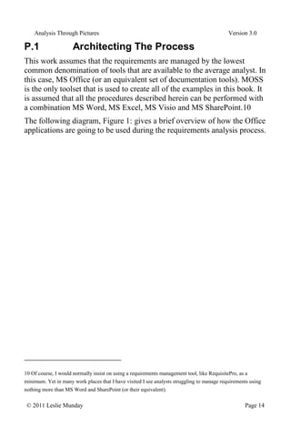
Version 3.0 © 2011 Leslie Munday Page 14 P.1 Architecting The Process This work assumes that the requirements are managed by the lowest common denomination of tools that are available to the average analyst. In this case, MS Office (or an equivalent set of documentation tools). MOSS is the only toolset that is used to create all of the examples in this book. It is assumed that all the procedures described herein can be performed with a combination MS Word, MS Excel, MS Visio and MS SharePoint.10 The following diagram, Figure 1: gives a brief overview of how the Office applications are going to be used during the requirements analysis process. 10 Of course, I would normally insist on using a requirements management tool, like RequisitePro, as a minimum. Yet in many work places that I have visited I see analysts struggling to manage requirements using nothing more than MS Word and SharePoint (or their equivalent).
16.
Analysis Through Pictures
Version 3.0 © 2011 Leslie Munday Page 15 +documentRequirements() +useCase MS Word +organizeListData() +listData MS Excel +controFile() +maintain List() +document +listData SharePoint +modelVisually() +models MS Visio Performs Data Operations On Edits Documents In Edits Models In Embeds Diagrams From Provides Hyperlinks To Figure 1: Configuration Of Tools With Microsoft Office SharePoint Services (MOSS) installed the integration between these tools is automated. I.e., SharePoint file management functions may be accessed directly from the other tools. P.1.1 Tools The following MS Office tools are used by the requirements process: MS Word – will be used to maintain use cases and provide all information through documents. MS Visio – is used for modeling the requirements in UML and producing supporting diagrams, such as architecture and wireframes. MS SharePoint – is used as a repository, to control the documents, requirements, organize lists and manage diagrams.
17.
Analysis Through Pictures
Version 3.0 © 2011 Leslie Munday Page 16 MS Excel - is used to manipulate lists of items used by the project and to generate reports about information in the SharePoint repository. P.1.2 Relationships The relationships between the tools are as follows: SharePoint lists can be exported to Excel, manipulated and imported back to SharePoint, if necessary. Documents are edited in Word and stored in SharePoint repositories. UML model and diagram files are edited in Visio and stored in SharePoint. Diagrams that are edited with Visio can be embedded into Word documents. MS Word uses hyperlinks that are provided by items in a SharePoint repository. P.2 Using Styles and Properties Microsoft Office was designed to be a word processor, not a software development tool. Yet some analysts spend more time working with text in a word processing application (or data in a spreadsheet) than possibly any analysis specific tool. Why is this! Maybe it is because MS Word it is the lowest common denominator application that everyone (who needs access to the requirements), is familiar with. This means that analysts often find that their development tools are specified by the business11 . Also consider that traditionally, requirements are expected to be in the form of text (often English), each beginning with a capital letter and ending in a period (full-stop). Yet English is possibly the worst language 11 Imagine programmers being told that the only tool they are going to be given to write code with is Notepad, because that is the only suitable tool that project managers (for example) have access to.
18.
Analysis Through Pictures
Version 3.0 © 2011 Leslie Munday Page 17 for specifying requirements. It contains endless ambiguities and duplicate words.12 Many attempts have been made at reducing English to a formal language, that is precise and unambiguous, but all have failed for the most part13 . So, reviewers want to see requirements written in their natural language, and if MS Word is quite capable of manipulating that natural language then why do analysts need anything else? We can at least go some way towards formalizing requirements written in English by removing many English words from our requirements specifications; adjectives and adverbs for example. Other improvements are to introduce a glossary into the project. We can also restrict the use of English to a subset of the language. If two words can convey the same meaning choose one, and use it consistently14 . A very powerful way to make requirements documents consistent is to make use of MS Word properties and styles. P.2.1 Properties One tool that MS Word provides us with to help with consistency is the ‘properties’ feature. Terms that are to be used consistently throughout a development effort may be assigned to a property. Instead of typing the phrase or word into your requirements document, select the property, insert it at the appropriate place and it will look the same wherever it is used. If at some stage the project decides to rename the word, it is simply changed in the property field and all instances of its use are automatically updated. 12 Personally, I think of requirements as a form of software, but at a higher level of abstraction than source code or design. I would like the tools used to develop the requirements to be a little more sophisticated than simple text manipulation tools. 13 I have been exposed to Z, VDM and even the part of UML named OCL, but even I admit being baffled by some of the constructs of these languages. 14 We are not writing a romance novel; requirements are boring on purpose.
19.
Analysis Through Pictures
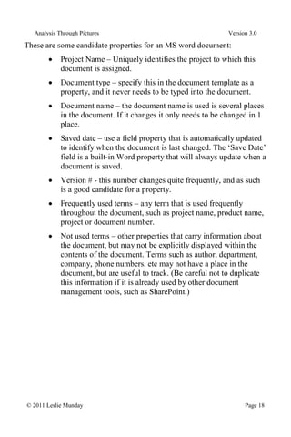
Version 3.0 © 2011 Leslie Munday Page 18 These are some candidate properties for an MS word document: Project Name – Uniquely identifies the project to which this document is assigned. Document type – specify this in the document template as a property, and it never needs to be typed into the document. Document name – the document name is used is several places in the document. If it changes it only needs to be changed in 1 place. Saved date – use a field property that is automatically updated to identify when the document is last changed. The ‘Save Date’ field is a built-in Word property that will always update when a document is saved. Version # - this number changes quite frequently, and as such is a good candidate for a property. Frequently used terms – any term that is used frequently throughout the document, such as project name, product name, project or document number. Not used terms – other properties that carry information about the document, but may not be explicitly displayed within the contents of the document. Terms such as author, department, company, phone numbers, etc may not have a place in the document, but are useful to track. (Be careful not to duplicate this information if it is already used by other document management tools, such as SharePoint.)
20.
Analysis Through Pictures
Version 3.0 © 2011 Leslie Munday Page 19 Figure 2: Document Properties Window Figure 2: shows the properties that are defined for the document that you are reading. These include the Project Name – Analysis Through Pictures, Document Type - Chapter, Document Name – Concerning MS Office and Version # - P.1. Once you have created your set of document properties you will want to use them in the body of the document. Whenever it is appropriate to use a property value simply insert the property field code instead of typing its value.
21.
Analysis Through Pictures
Version 3.0 © 2011 Leslie Munday Page 20 For example, many documents introduce themselves with the text ‘The purpose of this <document name> is to etc’. (Where the text in angled brackets <..>, is the property name.) Instead of typing the document name, insert the ‘Document Name’ property as a field. Update15 this field in the document each time its value changes.16 P.2.2 Styles Perhaps the most powerful tool that technical writers of Word documents are supplied with are Styles. Styles allow quick and consistent editing of Word documents. Before MS Word there was a document publishing system named Interleaf. Interleaf was designed specifically for writing technical documents, and introduced the idea of classes and objects in document processing. Each paragraph in an Interleaf document is an ‘object’. Each object is an instance of a class. Classes are assigned attributes. The attributes define the format of the paragraph; i.e., its size, font, color and other formatting attributes. Objects may be moved within the document and they retain their attribute values wherever they are located. Changing the attributes of a class updates the formatting of every object of that type of class within the document. Consistency is prevalent throughout the document.17 Interleaf no longer exists, but how many technical document writers are making use of similar features that are built into MS Word? MS Word assigns every character in a document to a ‘style’. A style is similar to the class concept of Interleaf. A style is a predefined format that may be applied to document characters, words or paragraphs. By default Word will assign text that is typed into a document to a style named 15 Why Word insists on the property being manually updated is beyond my comprehension. 16 For details on how to use properties with MS Word 2007 you may download a presentation on Working With Styles And Properties from my website, http://www.umllmu.com. 17 Unfortunately, powerful as Interleaf was, it only ran under a Unix OS, and each seat was very expensive.
22.
Analysis Through Pictures
Version 3.0 © 2011 Leslie Munday Page 21 'Normal'. To change the format from Normal, you assign the selected text to its appropriate style.18 Figure 3: shows the list of styles that are being used to write this book. 18 Prior to using office 2000, I was not even aware that this feature was available to MS Word. Word 2003 improved the styles feature and it became quite usable. Unfortunately, MS Word 2007 has (IMO), decreased the efficiency of using styles over 2003.
23.
Analysis Through Pictures
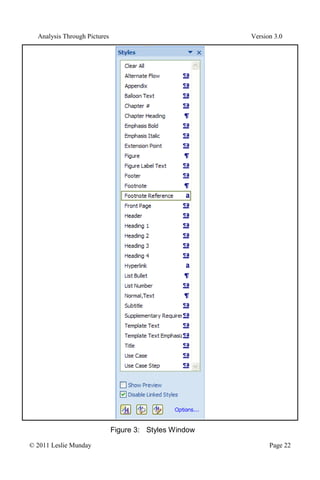
Version 3.0 © 2011 Leslie Munday Page 22 Figure 3: Styles Window
24.
Analysis Through Pictures
Version 3.0 © 2011 Leslie Munday Page 23 Every paragraph of every chapter, in this book is assigned to one of these styles. 19 Try to give styles names that reflect the purpose for creating the style. Some examples in this document are: Alternate Flow – Automatically numbers alternate flow headings in a use case. Appendix – Automatically numbers appendix headings. Emphasis Bold – Used to highlight text. Emphasis Italic – Used to italicize text. Extension Point – Used to automatically number use case extension headings. Figure Label Text - Used to give document figures a consistent caption. Heading (1-4) – Four heading levels; these are the standard Word headings. List Bullet – Used to create an unordered list. List Number – Used to create an ordered list of items. Normal, Text – The default Word style (this is the ‘normal’ style renamed). Supplementary Requirement – Used to identify that a paragraph is a supplementary requirement. Template Text – Used for instructional text in a document template. Use Case Step -This style automatically numbers the steps of a use case.20 Note that ‘Clear All’ is not actually a style in itself. Clicking on ‘Clear All’ sets the text style to ‘Normal’. The following sections describe some ways in which you may use styles to make your documentation effort more efficient. P.2.2.1 Defining Styles 19 A nice feature that Word 2007 did introduce is the ability to restrict formatting of documents such only the formatting allowed is according to styles that have been predefined in the document template. 20 These styles are available in the Application Use Case template on my website,
25.
Analysis Through Pictures
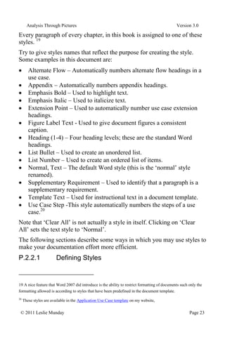
Version 3.0 © 2011 Leslie Munday Page 24 Styles are assigned to a Word document template. when. When a document is created from that template it automatically inherits the templates styles. Start by creating a new template from Word’s ‘Normal.dot’ template. Display the styles window pane and modify and add styles as appropriate. The ‘normal.dot’ styles are shown in Figure 4:. Figure 4: Normal Styles
26.
Analysis Through Pictures
Version 3.0 © 2011 Leslie Munday Page 25 Rename styles that you wish to keep with a name that represents when the style is to be used. For example, if you think that the ‘Book Title’ style is appropriate for text on the front cover of your document, rename it to ‘Front Cover’. In this manner users of your template do not have to guess where to use the style. Similarly, because it is named ‘Front Cover’, it should be apparent to your template users that this style should not be used in the body of the document. As a minimum you should define a style for each type of requirement that can be entered into the document. (Even if the formatting is identical, each requirement type needs its own style name.) The requirement types used in this book are the use case step, the use case and the supplementary requirement type. (Note, that supplementary requirement style is also applied to business rules. This can easily be renamed in the business use case template.) In addition to the formatting options, there are 3 style settings that may be applied to Word styles. P.2.2.2 Style Type There are 5 style types that may be selected from the dropdown list. Only the Linked Type is of interest; the others are subsets of the ‘Linked’ style type. If in doubt, set every style to type ‘Linked’ whenever possible (some preset styles do not allow their type to be changed). When using a linked style, if a selection of text is highlighted when the style is invoked, only the selected text is assigned to that style. If no text is selected when the cursor is located inside a paragraph, and the style is selected, the whole paragraph is assigned to that style. Style Based On All styles by default are based upon the ‘Normal’ style. That is to say that if you create a new style and do not change its formatting in any way it will appear exactly the same as the ‘Normal’ style when applied to text. By basing a style upon an existing style, of the same style type the style automatically adopts the formatting of that style. Now you may adjust the formatting as appropriate. (The ‘template text emphasized’ style is based on the ‘template text style, but with bold type added. If the ‘template text
27.
Analysis Through Pictures
Version 3.0 © 2011 Leslie Munday Page 26 style’ is modified, the ‘template text emphasized’ style adopts the changes automatically.) Style for Following Paragraph This is a useful feature that saves the effort of selecting a style for a paragraph, by having Word automatically assign the correct style to the next paragraph after the current style. (Note that this feature only applies to a new paragraph that is inserted after the current paragraph. It does apply to an existing paragraph, nor does it apply to selected characters that are assigned to a style.) For example, the ‘Alternate Flow’ and ‘Extension Point’ headings are always followed by at least one use case step. Similarly a use case step is normally (but not always), followed by another use case step. These 3 styles types have the ‘Style for following paragraph’ set to ‘Use Case Step’. By default the following paragraph is assigned to the this style being edited. Another good example is the ‘figure’ style, which is always followed by the ‘figure label text’ style when assigned to a figure in the document. P.2.2.3 Tips for Working With Styles It may be easier to create new styles from scratch, rather than attempt to alter existing Word styles. (Some styles are extremely obstinate when attempting to change their formatting properties.) All styles may be hidden from view, and only the desired styles shown in the styles list. Once you have defined enough styles to start working with your template, create a document from the template and start filling it out. (You are going to discover that more styles are needed as you complete the document, so keep the template handy.) As you discover that you need to add a style or modify an existing style, create or modify the style in the document template (not in the document) and import the template styles into your document. Do not edit styles directly in the document, unless that style is only ever going to be used in that document. Any style that could be used in more than one document should be edited in the template.
28.
Analysis Through Pictures
Version 3.0 © 2011 Leslie Munday Page 27 The styles may be locked in the document template, by selecting the protection option. This prevents users of documents created from that template from modifying or creating styles21 . P.2.2.4 Template Text Templates generally contain instructional text about what goes into each section and how to organize the contents of the section. All of this text is assigned a style of type ‘template text’. (or some variation, such as ‘Template Text Bold’). While leaving the template text in the document, complete the sections of the document, causing the template text and document text to become intertwined. This is fine, because when you are ready to remove the template text, simply select all instances of the template text and delete them. (This is 2 commands in MS Word 2007.) This is such a simple procedure that it is no effort to retain the template text in the working version of your document and only remove the template text when the document is to be published. [I have seen templates that were accompanied by a document named ‘Template Instructions for <document type>. The reason for this was because the analysts felt it was a lot of effort to remove thousands of template text instructional words from the document. The result of course is that two documents are maintained in tandem (duplication again) and because the instructions are in a separate document, you need both documents open in order to complete a document that is derived from the template.] P.2.2.5 Formatting Text If you have set all of your styles to the ‘Linked’ type, then in order to format a complete paragraph simply place your cursor in the paragraph and select the style; or to assign characters in a paragraph to a style, highlight those characters and select the style. 21 The protection may also be password protected, if you feel courageous enough to enforce your styles on your users.
29.
Analysis Through Pictures
Version 3.0 © 2011 Leslie Munday Page 28 Selected or highlighted text may encompass several paragraphs, allowing many paragraphs to be assigned to a style in a single action.22 Since styles operate on paragraphs in a document by default, it might be easier if we can see where a paragraph begins and ends. To do this, select the display paragraph marks option in your Word document. Every paragraph is delimited with an ‘end of paragraph’ mark, as shown in Figure 5: Figure 5: Paragraph Mark P.2.2.6 Example Situations For Using Styles Take the situation where text has been assigned a certain style, but at some time later a decision is made to change the formatting of that style. Simply open up the template from which the document is based. Change the style as appropriate within the template, and then import the style into the document. All text in the document of that style is automatically updated to reflect the change in formatting. What about the situation whereby you open up a document to discover that the wrong style has been applied throughout? Suppose that you wish to change all text of style ‘List Number’ to be style ‘List Bullet’. Simply select all text assigned to style ‘List Number’, and select the correct style; in this case ‘List Number’. Maybe you need to produce a report of all the supplementary requirements in your use case documents. This report is a document that lists just supplementary requirements each on a separate line. Simply create a ‘Supplementary Requirements Report’ document (from a template that includes the ‘Supplementary Requirement’ style). Open up each requirements document in turn; select all text of style ‘Supplementary 22 At this point I have just discovered that in Word 2007, if text is selected across paragraphs and its style is changed all paragraph text is changed, not just the selected text. So, if you wish to change a selection of text across paragraphs to a certain style, but not the whole paragraph, you will need to assign text to a style for each paragraph. Alternatively combine all text into a single paragraph, assign to the correct style and then insert paragraph marks. That works too.
30.
Analysis Through Pictures
Version 3.0 © 2011 Leslie Munday Page 29 Requirement’, and copy; then paste into your supplementary requirements report. One final example23 ; suppose that you are given a request, by the business, to highlight every instance of where money is referenced in the use cases (maybe it’s a SOX applicable request). Using MS Word’s search capabilities, find every instance of ‘$*’ in the use case steps. Assign them a temporary ‘Paragraph’ type style (call the style SOX for example). Every step in the use cases that contains a reference to ‘$’s can now be selected by selecting all styles of type ‘SOX’.24 P.2.2.7 The Style Area Pane There is an option in MS Word to set a value for the ‘Style Area Pane’, in inches. Setting this to 1” should be sufficient for you to be able to recognize the style names in your document. After you have set the style pane value switching to ‘Outline View’ causes all of the paragraph styles in use in your document to be displayed in this pane. P.2.2.8 Unwanted Styles Prior to publishing any document check the styles pane to make sure that no rogue styles have been introduced into the document. (This may occur as a result of pasting text of an unwanted style into the body of the document.) Select all text of that style and then set it to the correct style. Then remove the unwanted style from the document styles display window. P.2.3 MS Word Summary Use of MS Word processing tools for requirements management should be kept to performing only those functions that the tool was built to provide. Tasks such as traceability, managing requirements and analysis modeling should be performed by tools that were designed (and implemented) to execute these tasks efficiently. 23 And this may be stretching a typical situation a bit far 24 At places where I have worked that were SOX compliant we have had to cut out just the applicable SOX requirements from documents and send them to the financial business group. They did not want to receive anything that was of no interest to them.
31.
Analysis Through Pictures
Version 3.0 © 2011 Leslie Munday Page 30 Those analysis tasks that word processors were intended to perform, are: Editing text and ensuring correctness of spelling, grammar and punctuation. Formatting of text, using styles. Maintenance of document properties, or attributes. If your word processing tool does not support these functions as a minimum, then consider alternatives or you may find yourself doing a lot of rework. [Addendum: Perhaps the easiest way to modify MS Word document properties is through a file explorer. It is possible to open a document’s properties directly from the file menu. These may be edited and saved, without having to open the file in MS Word and then located the document properties.] P.3 Organizing SharePoint SharePoint is a document and list management tool that can be accessed through an intranet or extranet. It allows for version management of documents and provides some control over who may edit a document. Using SharePoint is detailed in subsequent chapters. P.3.1 MS Visio Visio comes with a UML modeling template and diagram organizer. (This may have to be installed as an add-in feature.) All diagram examples in this book were produced with MS Visio. P.3.2 MS Excel Excel is useful for manipulating SharePoint lists and producing reports. It’s use is kept to a minimum, and therefore there are no additional recommendations for working with Excel. P.4 Summary Remember that every process and artifact described in this book is intended to be tool independent. Microsoft tools are used for the examples, purely as a toolset that most readers will be familiar with and because graphic examples are required to clarify the text.
Download


![Analysis Through Pictures Version 3.0
© 2011 Leslie Munday Page 9
pseudo assembler code onto programming sheets, then coding BASIC
onto punch cards. When I left school I had been allowed to enter
commands to a remote computer directly through a teletype, and get an
almost immediate response (sometimes within seconds).
When I graduated I worked at a school that wanted me to teach
Mathematics, but allowed me to also teach Computer Science as a
secondary subject. It was here that I had my first access to a PC; the
Commodore Pet.
The vast majority of my early programming experience was with
assembler, using a direct terminal or sometimes punched tape and other
times by entering the machine code directly into memory via a series of
switches.
After 5 years of programming, I took a job writing requirements
documentation from which external subcontractors would develop the
code. This was my first experience with requirements analysis and the first
time that I needed to understand a ‘real’ SDLC7
.
From there my job title became aerospace Systems Analyst and this has
driven my career ever since. While working in aerospace I was subjected
to various development notations, from structured analysis, (Yourdon,
DeMarco, etc) to object object-oriented analysis (Shlaer/Mellor, Booch
and Rumbaugh). Eventually UML came along and all the other notations
were dropped in favor of this unified language coming out of Rational.
[Well, almost all – it was through my knowledge of Shlaer/Mellor that I
moved from Aerospace into Telecommunications.]
Once the aerospace funding shriveled up, I found myself leaving the
relative safety of aerospace and moved into the big, bad, scary world of
commercial enterprise. My interests in RUP and Business Analysis have
come about from working with commercial enterprise systems.
After reading books on RUP, and studying the application (that is now
supplied by IBM), I decided that the process needed to be described in a
sequential manner with actual steps that an analyst and project manager
could follow. RUP describes a very heavyweight development process. In
7
By ‘real’ I mean that we defined the process and required documents prior to writing and debugging the code](https://image.slidesharecdn.com/book0-250917203438-ecd9f714/85/Analysis-Through-Pictures-Introduction-pdf-10-320.jpg)
![Analysis Through Pictures Version 3.0
© 2011 Leslie Munday Page 27
The styles may be locked in the document template, by selecting the
protection option. This prevents users of documents created from that
template from modifying or creating styles21
.
P.2.2.4 Template Text
Templates generally contain instructional text about what goes into each
section and how to organize the contents of the section. All of this text is
assigned a style of type ‘template text’. (or some variation, such as
‘Template Text Bold’).
While leaving the template text in the document, complete the sections of
the document, causing the template text and document text to become
intertwined.
This is fine, because when you are ready to remove the template text,
simply select all instances of the template text and delete them. (This is 2
commands in MS Word 2007.)
This is such a simple procedure that it is no effort to retain the template
text in the working version of your document and only remove the
template text when the document is to be published.
[I have seen templates that were accompanied by a document named
‘Template Instructions for <document type>. The reason for this was
because the analysts felt it was a lot of effort to remove thousands of
template text instructional words from the document. The result of course
is that two documents are maintained in tandem (duplication again) and
because the instructions are in a separate document, you need both
documents open in order to complete a document that is derived from the
template.]
P.2.2.5 Formatting Text
If you have set all of your styles to the ‘Linked’ type, then in order to
format a complete paragraph simply place your cursor in the paragraph
and select the style; or to assign characters in a paragraph to a style,
highlight those characters and select the style.
21
The protection may also be password protected, if you feel courageous enough to enforce your styles on your
users.](https://image.slidesharecdn.com/book0-250917203438-ecd9f714/85/Analysis-Through-Pictures-Introduction-pdf-28-320.jpg)
![Analysis Through Pictures Version 3.0
© 2011 Leslie Munday Page 30
Those analysis tasks that word processors were intended to perform, are:
Editing text and ensuring correctness of spelling, grammar and
punctuation.
Formatting of text, using styles.
Maintenance of document properties, or attributes.
If your word processing tool does not support these functions as a
minimum, then consider alternatives or you may find yourself doing a lot
of rework.
[Addendum: Perhaps the easiest way to modify MS Word document
properties is through a file explorer. It is possible to open a document’s
properties directly from the file menu. These may be edited and saved,
without having to open the file in MS Word and then located the
document properties.]
P.3 Organizing SharePoint
SharePoint is a document and list management tool that can be accessed
through an intranet or extranet. It allows for version management of
documents and provides some control over who may edit a document.
Using SharePoint is detailed in subsequent chapters.
P.3.1 MS Visio
Visio comes with a UML modeling template and diagram organizer. (This
may have to be installed as an add-in feature.) All diagram examples in
this book were produced with MS Visio.
P.3.2 MS Excel
Excel is useful for manipulating SharePoint lists and producing reports.
It’s use is kept to a minimum, and therefore there are no additional
recommendations for working with Excel.
P.4 Summary
Remember that every process and artifact described in this book is
intended to be tool independent. Microsoft tools are used for the examples,
purely as a toolset that most readers will be familiar with and because
graphic examples are required to clarify the text.](https://image.slidesharecdn.com/book0-250917203438-ecd9f714/85/Analysis-Through-Pictures-Introduction-pdf-31-320.jpg)