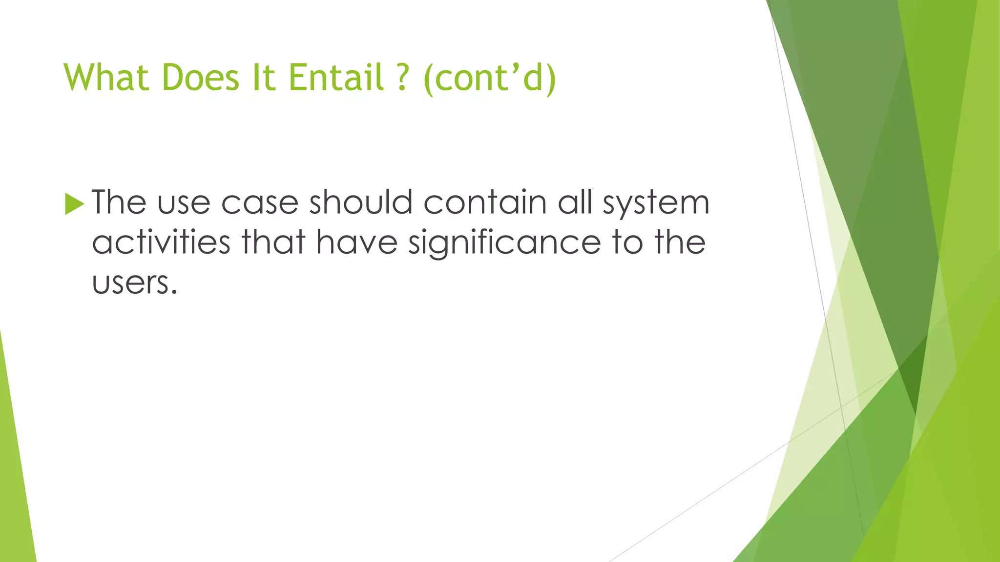
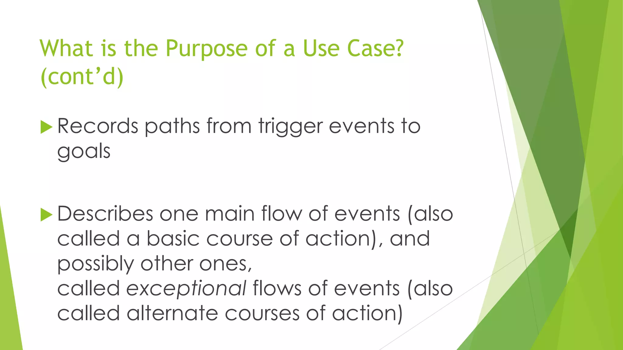
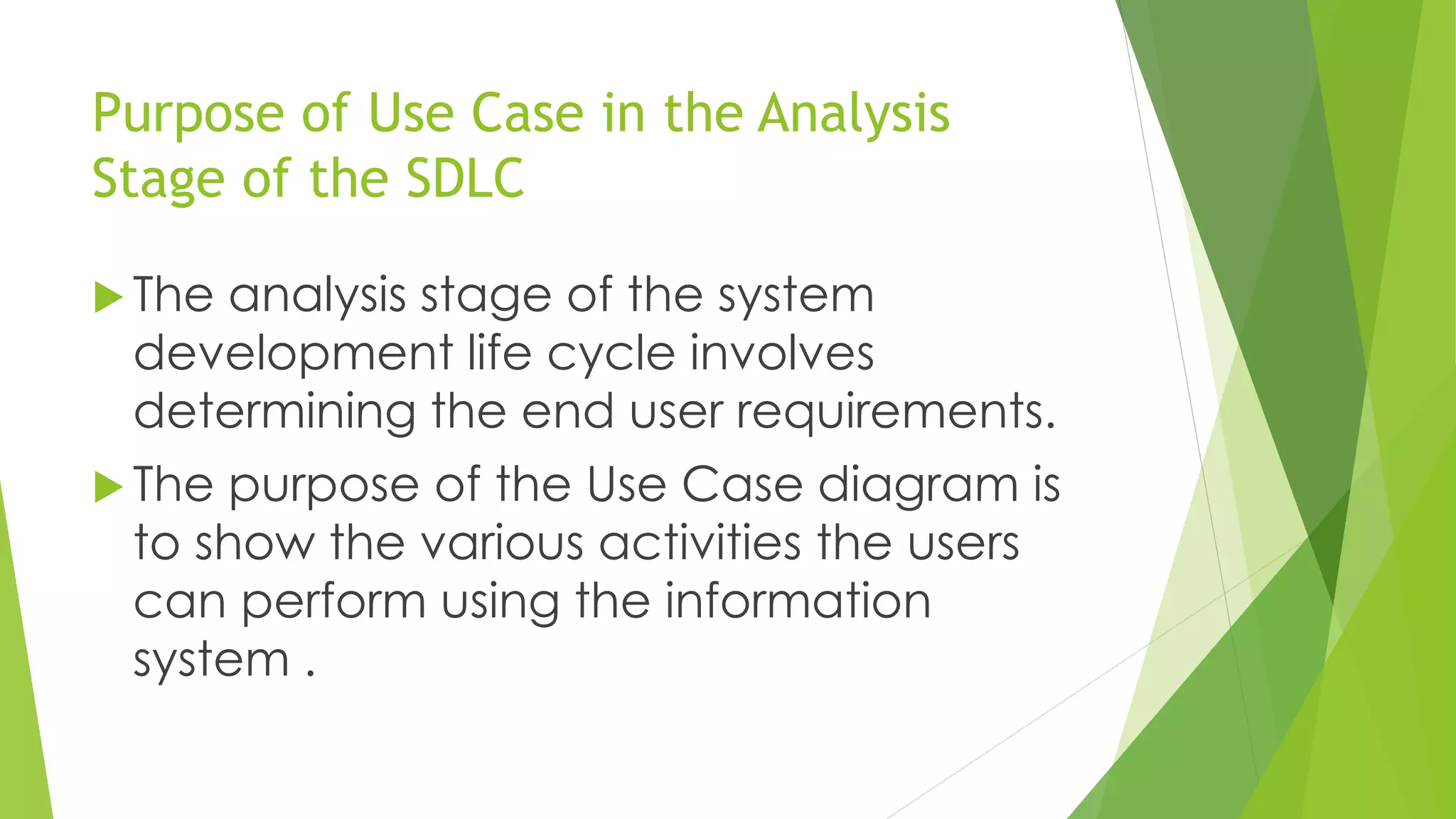
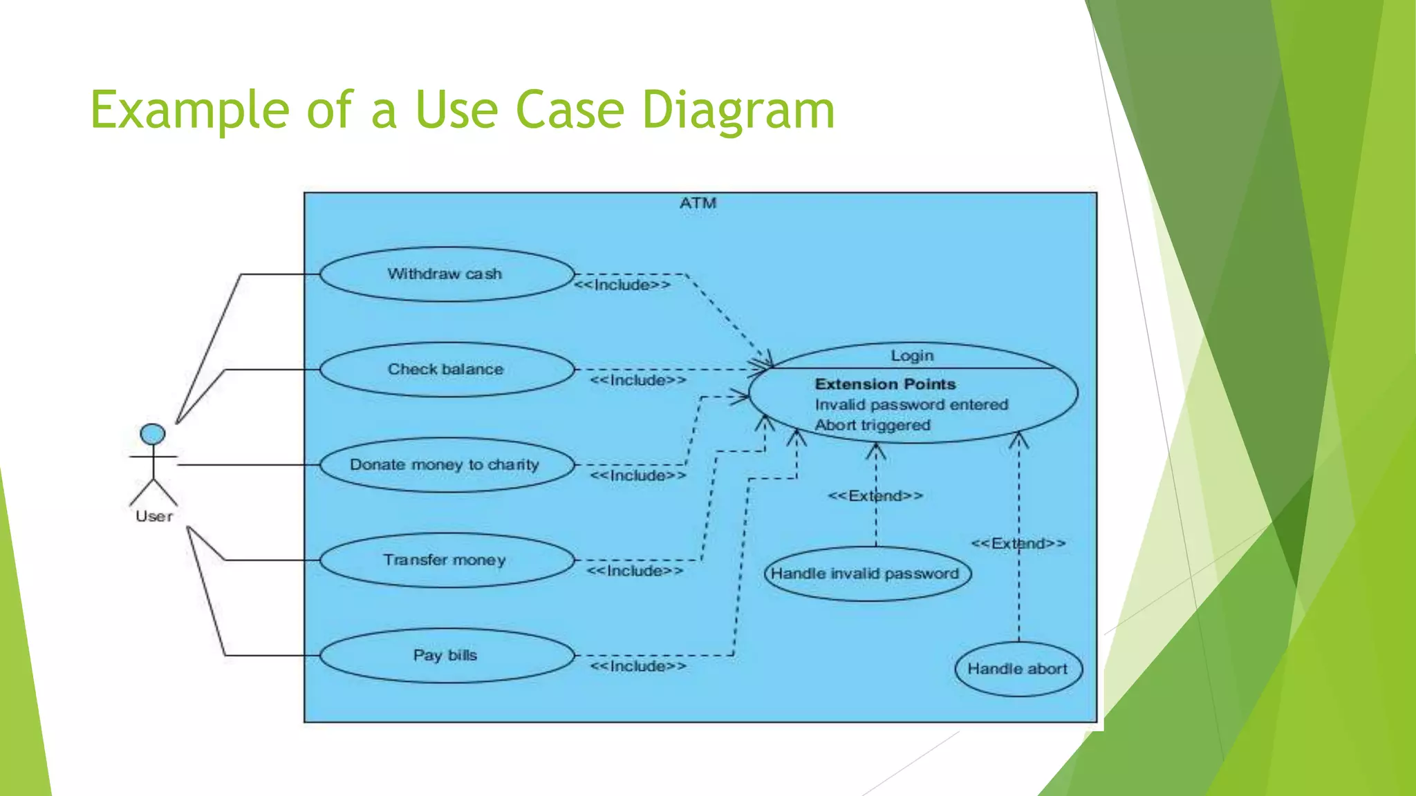
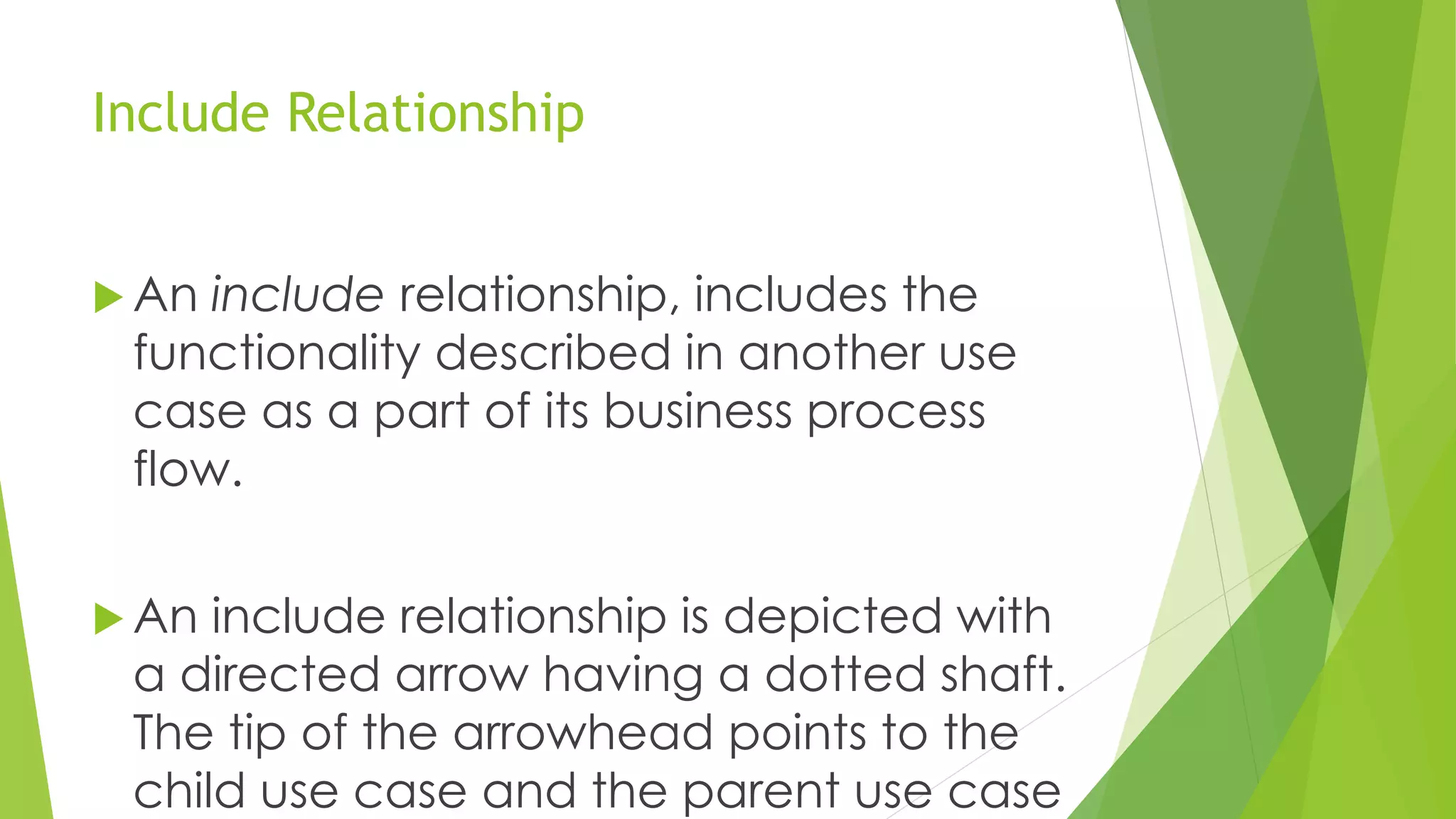
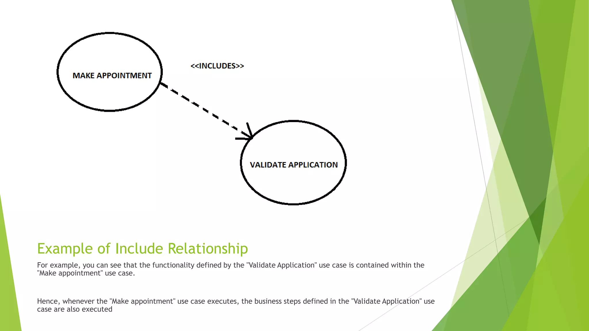
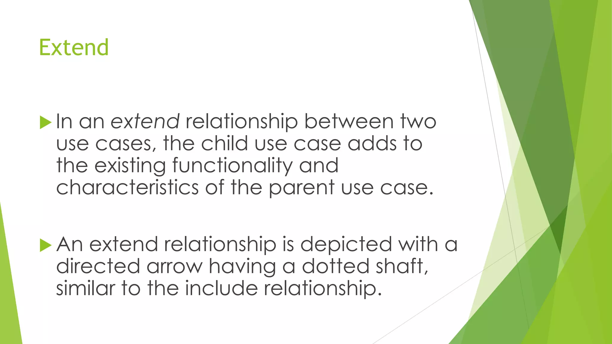
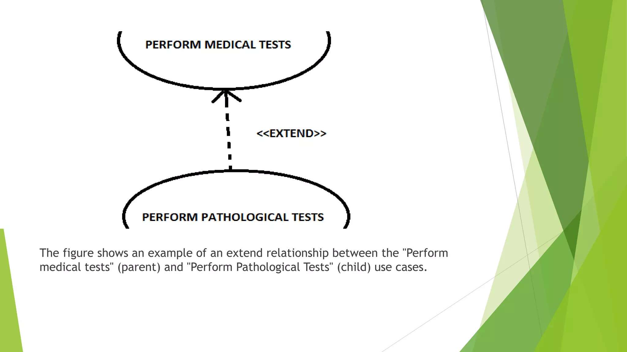
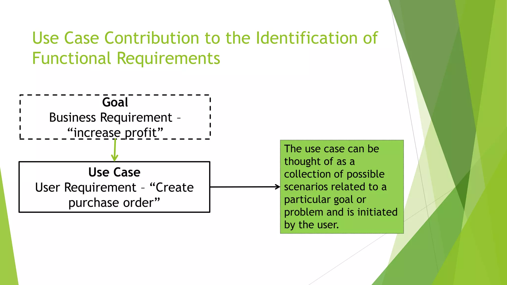
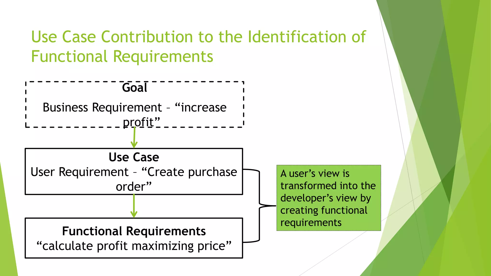
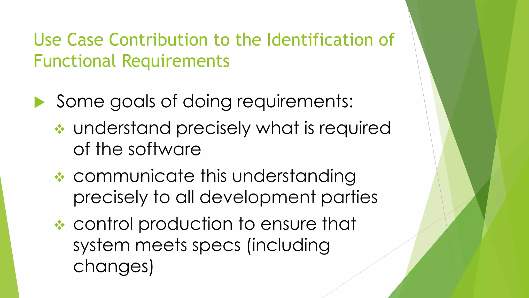
USE CASE ANALYSIS AND
DIAGRAMMING
Group 1
Regina Shakespeare
Ornella Dunn
Odaine McMillan
Sherece Doyley
Courtney Francis
Objectives
 Define Case and Use Case
Diagramming
 The Purpose of a Use Case
 The Elements of a Use Case
 Contribution to the Identification of
functional requirements
 Construct a Use Case Diagram
What is a Use Case?
 A use case is a form of technique used
in system analysis. It is used to identify,
clarify, and organize system
requirements.
 A use case diagram is a simple
representation of the users/actors'
interaction within the case system.
What Does It Entail?
 It consists of a group of elements that
can be used together in a way that will
have an effect larger than the sum of
the separate elements combined.
 The elements are, the actor, the use
case, the system boundary, & system
association. In some cases it may also
consist of, extend and include elements.
What Does It Entail ? (cont’d)
 The use case should contain all system
activities that have significance to the
users.
What is the Purpose of a Use Case?
 Used to gather requirements of a system.
 Used to get an outside view of a system.
 Identify external and internal factors
influencing the system.
What is the Purpose of a Use Case?
(cont’d)
 Records paths from trigger events to
goals
 Describes one main flow of events (also
called a basic course of action), and
possibly other ones,
called exceptional flows of events (also
called alternate courses of action)
Purpose of Use Case in the Analysis
Stage of the SDLC
 The analysis stage of the system
development life cycle involves
determining the end user requirements.
 The purpose of the Use Case diagram is
to show the various activities the users
can perform using the information
system .
Example of a Use Case Diagram
Elements of a Use Case
 Actor
 Use Case
 System Boundary
 An Association Relationship
The Actor
What is an Actor?
 An actor portrays any entity (or entities)
that perform certain roles in a given
system.
 The different roles the actor represents
are the actual business functions of users
in a given system.
 An actor in a use case diagram interacts
with a use case.
 For example, for modeling a visa
application at the embassy, a customer
entity represents an actor in the
application.
 Also the receptionist who processes the
applications at the counter is also an
 However decision resides with you to
determine what actors make an impact
on the functionality that you want to
model.
 If an entity does not influence the any
function of the process you are
modeling, it cannot be represented as
the actor.
System Boundary
 A system boundary defines the scope of
what a system will be and/or its intended
function.
 A system boundary in a use case
diagram also describes the limits and
restrictions of the system.
 The system boundary is shown as a
rectangle spanning all the use cases in
 This drawing depicts the system boundary of a visa application. The use cases of this system
are enclosed in a rectangle. Note that the actors in the system are outside the system
boundary.
Association Relationship
 Use cases share different kinds of relationships. A
relationship between two use cases is basically a
dependency between the two use cases.
 Use case relationships can be one of the following:
• Include
• Exclude
Include Relationship
 An include relationship, includes the
functionality described in another use
case as a part of its business process
flow.
 An include relationship is depicted with
a directed arrow having a dotted shaft.
The tip of the arrowhead points to the
child use case and the parent use case
Example of Include Relationship
For example, you can see that the functionality defined by the "Validate Application" use case is contained within the
"Make appointment" use case.
Hence, whenever the "Make appointment" use case executes, the business steps defined in the "Validate Application" use
case are also executed
Extend
 In an extend relationship between two
use cases, the child use case adds to
the existing functionality and
characteristics of the parent use case.
 An extend relationship is depicted with a
directed arrow having a dotted shaft,
similar to the include relationship.
Extend
 The tip of the arrowhead points to the
parent use case and the child use case
is connected at the base of the arrow.
The figure shows an example of an extend relationship between the "Perform
medical tests" (parent) and "Perform Pathological Tests" (child) use cases.
 The "Perform Pathological Tests" use case
enhances the functionality of the
"Perform medical tests" use case.
 The "Perform Pathological Tests" use case
is therefore a specialized version of the
generic "Perform medical tests" use
case.
Use Case Contribution to the Identification of
Functional Requirements
 The purpose of use-case is to reveal the
functional requirements of a system.
 Functional requirements captures the
behaviour of the system.
 It focuses on what an existing system
does or new system should do and NOT
how the system delivers or should deliver
those functions.
Use Case Contribution to the Identification of
Functional Requirements
 The use-case modeling is done in the
early stages of systems development to
help developers to clearly understand
the functional requirements.
 The use case contains all system
activities that have significance to the
users.
 Developers need to involve the users in
discussions throughout the model
development process to finally make an
agreement on the requirements
specifications.
Use Case Contribution to the Identification of
Functional Requirements
 When used to model functional
requirements, a use case describes one
function required of your system or
application.
 As such, your use cases constitute a
functional specification.
Use Case Contribution to the Identification of
Functional Requirements
Goal
Business Requirement –
“increase profit”
Use Case
User Requirement – “Create
purchase order”
The use case can be
thought of as a
collection of possible
scenarios related to a
particular goal or
problem and is initiated
by the user.
Use Case Contribution to the Identification of
Functional Requirements
Goal
Business Requirement – “increase
profit”
Use Case
User Requirement – “Create purchase
order”
Functional Requirements
“calculate profit maximizing price”
A user’s view is
transformed into the
developer’s view by
creating functional
requirements
Use Case Contribution to the Identification of
Functional Requirements
 Some goals of doing requirements:
 understand precisely what is required
of the software
 communicate this understanding
precisely to all development parties
 control production to ensure that
system meets specs (including
changes)
DEMONSTRATION

Use Case Analysis and Diagramming

  • 1.
    USE CASE ANALYSISAND DIAGRAMMING Group 1 Regina Shakespeare Ornella Dunn Odaine McMillan Sherece Doyley Courtney Francis
  • 2.
    Objectives  Define Caseand Use Case Diagramming  The Purpose of a Use Case  The Elements of a Use Case  Contribution to the Identification of functional requirements  Construct a Use Case Diagram
  • 3.
    What is aUse Case?  A use case is a form of technique used in system analysis. It is used to identify, clarify, and organize system requirements.  A use case diagram is a simple representation of the users/actors' interaction within the case system.
  • 4.
    What Does ItEntail?  It consists of a group of elements that can be used together in a way that will have an effect larger than the sum of the separate elements combined.  The elements are, the actor, the use case, the system boundary, & system association. In some cases it may also consist of, extend and include elements.
  • 5.
    What Does ItEntail ? (cont’d)  The use case should contain all system activities that have significance to the users.
  • 6.
    What is thePurpose of a Use Case?  Used to gather requirements of a system.  Used to get an outside view of a system.  Identify external and internal factors influencing the system.
  • 7.
    What is thePurpose of a Use Case? (cont’d)  Records paths from trigger events to goals  Describes one main flow of events (also called a basic course of action), and possibly other ones, called exceptional flows of events (also called alternate courses of action)
  • 8.
    Purpose of UseCase in the Analysis Stage of the SDLC  The analysis stage of the system development life cycle involves determining the end user requirements.  The purpose of the Use Case diagram is to show the various activities the users can perform using the information system .
  • 9.
    Example of aUse Case Diagram
  • 10.
    Elements of aUse Case  Actor  Use Case  System Boundary  An Association Relationship
  • 11.
  • 12.
    What is anActor?  An actor portrays any entity (or entities) that perform certain roles in a given system.  The different roles the actor represents are the actual business functions of users in a given system.
  • 13.
     An actorin a use case diagram interacts with a use case.  For example, for modeling a visa application at the embassy, a customer entity represents an actor in the application.  Also the receptionist who processes the applications at the counter is also an
  • 14.
     However decisionresides with you to determine what actors make an impact on the functionality that you want to model.  If an entity does not influence the any function of the process you are modeling, it cannot be represented as the actor.
  • 15.
    System Boundary  Asystem boundary defines the scope of what a system will be and/or its intended function.  A system boundary in a use case diagram also describes the limits and restrictions of the system.  The system boundary is shown as a rectangle spanning all the use cases in
  • 16.
     This drawingdepicts the system boundary of a visa application. The use cases of this system are enclosed in a rectangle. Note that the actors in the system are outside the system boundary.
  • 17.
    Association Relationship  Usecases share different kinds of relationships. A relationship between two use cases is basically a dependency between the two use cases.  Use case relationships can be one of the following: • Include • Exclude
  • 18.
    Include Relationship  Aninclude relationship, includes the functionality described in another use case as a part of its business process flow.  An include relationship is depicted with a directed arrow having a dotted shaft. The tip of the arrowhead points to the child use case and the parent use case
  • 19.
    Example of IncludeRelationship For example, you can see that the functionality defined by the "Validate Application" use case is contained within the "Make appointment" use case. Hence, whenever the "Make appointment" use case executes, the business steps defined in the "Validate Application" use case are also executed
  • 20.
    Extend  In anextend relationship between two use cases, the child use case adds to the existing functionality and characteristics of the parent use case.  An extend relationship is depicted with a directed arrow having a dotted shaft, similar to the include relationship.
  • 21.
    Extend  The tipof the arrowhead points to the parent use case and the child use case is connected at the base of the arrow.
  • 22.
    The figure showsan example of an extend relationship between the "Perform medical tests" (parent) and "Perform Pathological Tests" (child) use cases.
  • 23.
     The "PerformPathological Tests" use case enhances the functionality of the "Perform medical tests" use case.  The "Perform Pathological Tests" use case is therefore a specialized version of the generic "Perform medical tests" use case.
  • 24.
    Use Case Contributionto the Identification of Functional Requirements  The purpose of use-case is to reveal the functional requirements of a system.  Functional requirements captures the behaviour of the system.  It focuses on what an existing system does or new system should do and NOT how the system delivers or should deliver those functions.
  • 25.
    Use Case Contributionto the Identification of Functional Requirements  The use-case modeling is done in the early stages of systems development to help developers to clearly understand the functional requirements.  The use case contains all system activities that have significance to the users.
  • 26.
     Developers needto involve the users in discussions throughout the model development process to finally make an agreement on the requirements specifications.
  • 27.
    Use Case Contributionto the Identification of Functional Requirements  When used to model functional requirements, a use case describes one function required of your system or application.  As such, your use cases constitute a functional specification.
  • 28.
    Use Case Contributionto the Identification of Functional Requirements Goal Business Requirement – “increase profit” Use Case User Requirement – “Create purchase order” The use case can be thought of as a collection of possible scenarios related to a particular goal or problem and is initiated by the user.
  • 29.
    Use Case Contributionto the Identification of Functional Requirements Goal Business Requirement – “increase profit” Use Case User Requirement – “Create purchase order” Functional Requirements “calculate profit maximizing price” A user’s view is transformed into the developer’s view by creating functional requirements
  • 30.
    Use Case Contributionto the Identification of Functional Requirements  Some goals of doing requirements:  understand precisely what is required of the software  communicate this understanding precisely to all development parties  control production to ensure that system meets specs (including changes)
  • 31.