SlideShare a Scribd company logo
1 of 7
Download to read offline
INTRODUCTION
This paper considers the observed effects of both
single and multiple stone column installation in
soft clay and demonstrates that successful ground
improvement can be achieved with this technique.
A detailed explanation of the various Vibro Re-
placement and Compaction techniques available is
provided by Sonderman & Wehr (2004) and is not
repeated here. This paper concentrates on stone
columns installed using the dry bottom feed meth-
od, which is the most widely used technique in the
UK for routine projects on soft clay sites, often
preferred nowadays to the wet method. A signifi-
cant advantage of the dry bottom feed method over
the wet method is that a supply of water flush is
not required with the attendant requirement of
handling and disposal of the wet spoil. Numerous
case studies illustrating the use of the dry bottom
feed method for a wide range of projects have been
published, for example, Cooper & Rose (1999),
Wehr (2006), McNeill (2007), Castro (2007) and
Egan (2008).
Three aspects of the installation process are con-
sidered in this paper: (a) the ground response dur-
ing the installation of a dry bottom feed stone col-
umn, (b) changes to the soil stress field and pore
water pressure during the equalization period fol-
lowing stone column construction and (c) the in-
teraction effects resulting from the construction of
both small groups and large grids of columns.
THE CONCEPTUAL MODEL FOR INSTALLA-
TION OF A SINGLE COLUMN
An example of a modern bottom feed poker is
shown in Figure 1. The main body of the poker is
broadly cylindrical with a number of fins attached
which counteract the tendency for the poker to ro-
tate during column construction. The vibrating
motion is generated by an electric powered rotating
weight housed within the poker casing.
Observed installation effects of vibro replacement stone columns in soft
clay
D. Egan & W. Scott
Keller Ground Engineering, Ryton-on-Dunsmore, Coventry, UK
B. McCabe
Department of Civil Engineering, National University of Ireland, Galway, Ireland
ABSTRACT: The installation of vibro replacement stone columns in any soil causes significant changes to
the stress regime around each probe location. In soft clays, the principal effects are caused by a cavity expan-
sion mechanism as the probe is introduced into the soil and the stone column constructed. This paper presents
observations of changes in soil volume and pore water pressure during stone column installation.
The implications for the most suitable column construction techniques and the soil strength limiting column
construction arising from the observations are discussed. The data presented are also of interest to those vali-
dating numerical models of stone column installation, and issues relevant to the practical application of nu-
merical modeling are considered.
Figure 1 a typical bottom feed
poker
Remedy Geotechnics Ltd
Technical Paper R10
www.remedygeotechnics.com
The stone is fed to the base of the poker body
and compressed air flush is used to assist the stone
delivery. The air flush, which is channeled to the
bottom end of the poker, assists in creating a small
annulus between the poker and the ground, reduc-
ing frictional drag. The air flush also counteracts
the suction that the poker would generate as it is
withdrawn from the base of the column back up
the bore, and which could lead to the surrounding
soil moving back into the previously created void.
The electrical current drawn by the poker dur-
ing initial penetration of the ground and subse-
quent compaction of the stone provides an indica-
tion of the strength and stiffness of the ground.
Figure 2 compares the measured draw of electrical
current plotted against depth during the construc-
tion of a 5.5m long column in soft alluvial clay.
Also shown is the profile of undrained shear
strength from the site (estimated from cone pene-
tration test data). The increase in current draw with
increase of the undrained shear strength of the host
soil is clear. As there are a number of other factors
which can affect the current draw of the poker it is
not possible to develop a simple and universal rela-
tionship with soil strength. However the ability to
measure and record the current consumption does
offer a qualitative indication of the quality of col-
umn construction in soft soils where overworking
of the ground (a sign of poor workmanship) should
be avoided. This is one of the reasons why modern
dry bottom feed rigs, fitted with advanced instru-
mentation, can be used where hitherto the wet sys-
tem would have had to be adopted.
As the poker is lowered into the ground the soil
is mainly displaced laterally as a cavity is opened
up. Some vertical smearing of the soil adjacent to
the poker may occur, although there is little evi-
dence that this is significant, and some vertical
heave of the ground surface can result. The magni-
tude of heave is highly dependent on the arrange-
ment of columns being constructed as discussed
below.
HEAVE
Most experienced practitioners are aware that the
installation of stone columns into soft clay can
generate a degree of surface heave, particularly if
construction control is inadequate and overworking
of the ground takes place. Some degree of surface
heave during the installation of stone columns us-
ing the dry bottom feed method is inevitable and
demonstrates that the stress regime around the col-
umn is being altered and improvement of the
ground is being achieved and is not detrimental to
the final foundation performance. For this reason
heave is rarely measured (indeed it is not necessary
to do so). Nonetheless the few case studies where
heave was recorded are of interest as they show
that the amount of heave is a function of the col-
umn size, spacing, extent and construction method.
Castro (2007) reported a conical zone of surface
heave with a maximum value of 290mm following
the installation of a test group of seven columns.
0
0.5
1
1.5
2
2.5
3
3.5
4
4.5
5
5.5
6
0 25 50 75 100 125
Amps (A)
Depth(m)
0
0.5
1
1.5
2
2.5
3
3.5
4
4.5
5
5.5
6
0
20
40
60
80
100
120
140
160
180
200
Cu (kPa)
Depth
Figure 2. Poker current demand compared with un-
drained shear strength
Figure 3. Stone column and instrumentation lay-
out reported by Castro (2007)
Remedy Geotechnics Ltd
Technical Paper R10
www.remedygeotechnics.com
The columns were 0.8m in diameter, 9.0m long in-
stalled at 2.8m centres through soft to firm alluvial
clay by Keller Terra in Spain. Figure 3 shows the
column layout and the locations of piezometers in-
stalled prior to the stone column construction. It is
unclear if the heave reported was a local maximum
and the overall volume of heave was not reported.
Watts et al (2000) reported different amounts of
heave for different column densities in the soft
Carse clay at the Bothkennar test site in Scotland.
(Details of this site are fully discussed in Geotech-
nique, Volume 42, 1992). The columns were in-
stalled to a length of 6m using a Bauer HBM4 bot-
tom feed rig. The installation procedure followed
the now dated practice of ramming a large volume
of stone into the base of the columns creating an
enlarged toe of up to 1.25m diameter. Extensome-
ters revealed that most heave was generated by the
construction of the bulb, emphasising that this
practice is to be avoided if heave is to be con-
trolled. No heave was recorded for two columns
located at 1.5m centers (although 150mm of lateral
displacement was measured by inclinometer 0.5m
from the columns). Three columns at 2.0m centers
produced an average local increase in ground sur-
face of 107mm; four columns at 1.5m centers pro-
duced an average of 143mm of heave. A maximum
of 425mm heave was recorded due to installation
of 25 columns 6m long to support an 8.1m square
concrete test raft. The total volume of heave rec-
orded for these 25 columns equated to 27% of the
stone introduced into the ground.
Measurements of heave have also been made
during a few contracts performed by Keller
Ground Engineering in the UK. In Contract A in
Lincolnshire, an average of around 150mm of sur-
face heave was measured during the installation of
a large grid (80m x 70m) of 5m long 450mm di-
ameter columns in soft alluvial clay
(20kPa<Cu<50kPa, 30%<w<70%). The columns
were installed on a 2m by 2m square grid and the
volume of heave equated to 75% of the volume of
stone in the columns. In another contract (Contract
B), three separate rows each comprising five col-
umns (550mm diameter and 5.5m long) were in-
stalled in Carse clay. Contours of the average
magnitude of heave, estimated from a grid of lev-
els taken around each column group, are shown in
Figure 4. The average maximum heave was around
70mm along the centreline, diminishing with dis-
tance from the columns. In this case, the volume of
heaved ground was estimated to be approximately
35% of the volume of stone installed in the col-
umns. While the phenomenon of heave is occa-
sionally referred to in the literature, very little
quantitative guidance is available to estimate how
much heave can be expected for any given column
arrangement.
Defining the Perimeter Ratio P and Heave Ratio
Hp according to equations [1] and [2] below ap-
pears to allow a relationship to be developed, and
values of P and Hp are shown in Table 1 for the
case histories discussed above.
(1)
Hp = Volume of heaved ground (2)
Volume of stone columns
Reference
Number of
columns in
group
Column
length
Average
column
diameter
Arrangement
Perimeter
ratio, P
Heave
percentage, Hp
m mm %
Castro (2007) 7 9 800 2.8m spacing 1.05 12
Watts et al
(2000)
8.1m raft
2 Columns
3 Columns
4 Columns
25
2
3
4
6
6
6
6
940
940
940
940
1.5m centers around
edge of raft 5 in centre
-
-
-
2.28
0.99
0.99
1.21
27
0
3
5
Keller Contract
B
5 5.5 550 Single line 1.5m cen-
ters
0.63 35
Keller Contract
A
‘Infinite’ 5 450 Infinite 2m square grid 6.6 75
grouptheofperimeterExternal
groupainperimetersColumn
P
Table 1. Data on observations of heave during column installation
Remedy Geotechnics Ltd
Technical Paper R10
www.remedygeotechnics.com
The data from Table 1 are plotted in Figure 5 and
while it is recognised that the database is limited
the data shown an interesting trend suggesting
some sort of relationship between column layout
and amount of heave exists. Further collection of
field data is recommended so that this relationship
can be substantiated.
Heave Summary
It is clear from a number of observations that the
process of constructing stone columns causes some
lateral and vertical soil displacement, and that the
proportion of lateral to vertical strain is a function
of the lateral confinement of the host ground and
adjacent stone columns. Single columns, rows and
small groups of columns exhibit less vertical heave
than large grids of columns. It also appears that
that the closer the column spacing for any given
column arrangement the greater the magnitude of
heave. In considering these data, variations in
ground conditions and installation practice be-
tween different sites is not considered and at this
stage and the trends shown in Figure 5 should be
considered indicative rather than definitive.
TOTAL STRESS AND CAVITY EXPANSION
The penetration of the vibro poker into the ground
and subsequent charging and compaction of the
stone aggregate may be modelled mathematically
by the theory of cylindrical cavity expansion, such
as that developed by Gibson and Anderson (1961).
As the process of stone column installation is rela-
tively quick in saturated soft clays, undrained cavi-
ty expansion is most applicable. Cavity expansion
theory comes in various forms, taking account of
(i) the required rigour in modelling soil behaviour
(elastic, elastic-plastic or critical state solutions),
(ii) whether the medium is finite or infinite, and
(iii) the effect of various initial radii on the cavity
stresses.
Using Gibson and Anderson’s (1961) elastic-
plastic theory, the zone of soil closest to the cavity
is in a plastic state and the soil beyond remains in
an elastic state. The radial extent of the plastic
zone, R, may be calculated as:
(3)
where p is the cavity pressure r is the radial total
stress at radius r, cu is the undrained shear strength
and a is the radius of poker. Cavity expansion is
effectively infinite in the case of a penetrating
poker (starting from zero initial radius and expand-
ing to radius a), in which case it is reasonable to
assume that the pressure in the cavity will have
reached the limit pressure (plim), calculated accord-
ing to:
(4)
where ho, E and are the free field horizontal to-
tal stress, Young’s modulus and Poisson’s ratio re-
spectively. In this instance, the radial stresses in
the plastic (r<R) and elastic (r>R) zones will be
given by equations [5] and [6] respectively:
(5)
(6)
-6 -5 -4 -3 -2 -1 0 1 2 3 4 5 6
-4
-3
-2
-1
0
1
2
3
4
-6 -5 -4 -3 -2 -1 0 1 2 3 4 5 6
-4
-3
-2
-1
0
1
2
3
4
Figure 4. Contours of heave around a line of stone
columns
)1(20lim
u
uh
c
E
cp
u
r
c
p
aeR 2
R
r
cc uuhr ln20
2
0
r
R
cuhr
Figure 5 Ground surface heave ratios for stone column
installation.
Surface Heave Ratios
0%
10%
20%
30%
40%
50%
60%
70%
80%
0.00 1.00 2.00 3.00 4.00 5.00 6.00 7.00
Perimeter ratio
HeaveRatio%
Small groups Largegrid 8.1mRaft
Remedy Geotechnics Ltd
Technical Paper R10
www.remedygeotechnics.com
The above equations were used to calculate the
stress field at 2m depth for Contract B. At this site
the clay was very soft with an undrained shear
strength, cu, of around 10kPa at this depth. The
stress field is shown in Figure 6, from which it can
be observed that the radius of the plastic zone is
1.4m, beyond which the mean horizontal stress is
unchanged from the initial (pre-column installa-
tion) values.
PORE PRESSURES AND CAVITY EXPAN-
SION
Observations During Column Construction
Kirsch (2003), Gab et al (2007) and Castro (2007)
measured the pore pressure response to the instal-
lation process in three separate studies. Figure 7
reproduces the data shown by Castro (2007) as an
example of the general trends. In all three cases the
pore pressure rose extremely rapidly as the poker
first penetrated the ground generally reaching a
peak when the probe achieved the same depths as
the piezometer. This is in keeping with general
trends observed for displacement piles (i.e. McCa-
be et al 2008). Sharp and significant fluctuations
in readings characterise the curves during column
construction and are attributed to a range of causes
including contact pressure fluctuations as the poker
is raised and lowered into the ground (low fre-
quency), cyclic vibrations from the poker (high
frequency ~50Hz), possibly effects from escape of
air flush into the ground and general consruction
vibration.
In all cases the pore pressures reached a quasi
static level, albeit at an elevated level, immediately
after completion of each stone column. Subse-
quent installation of adjacent columns leads to a
further increase in the quasi static levels.
Dissipation of the excess pore pressure is ob-
served, occurring at different rates, governed by
the permeability characteristics of the host soil.
Kirsch (2003) and Castro (2007) do not provide
dissipation data beyond the end of construction of
the column groups and it should be noted that the
columns appear to have been constructed in a high
silt content soil so may not be directly comparable
to stone columns constructed in soft clay. Castro
(2007) presents a finite difference analysis to esti-
mate the rate of drainage, however the measured
Figure 7. Pore water pressures measured during stone col-
umn construction (Castro (2007)
Figure 6. Stress field around a stone in soft Carse
clay
StressDistribution Around an Expanded Cavity in
Undrained Cohesive Soil
0
20
40
60
80
100
120
0 0.5 1 1.5 2 2.5 3 3.5 4 4.5 5
Radius(m)
Stress(kPa)
srdistribution
throughout
sq distribution
throughout
Meannormalstressin
horizontalplane,sm
RaplochData
Series5
Castroformulation
RaplochSite5FootingTrial
0
5
10
15
20
25
30
35
40
45
50
55
60
65
70
28-Aug
04-Sep
11-Sep
18-Sep
25-Sep
02-Oct
09-Oct
16-Oct
23-Oct
30-Oct
Date
Pressure(Pa)
FootingB2mdepth
FootingC2mdepth
FootingA2mdepth
FootingC4mdepth
Column
construction
Construct
footing
Load
footing
Figure 8 Piezometer response to column loading
Keller Carse clay site
Keller Contract B
Remedy Geotechnics Ltd
Technical Paper R10
www.remedygeotechnics.com
dissipation was approximately 10 times faster than
predicted by the theory. This was attributed to the
presence of ground fractures caused by the pene-
tration of the air flush during column installation
creating preferential drainage paths, but the actual
reasons were not conclusively proved.
Following Column Construction
Figure 8 shows the dissipation of measured pore
pressures from Keller Ground Engineering Con-
tract B. The piezometers were BAT-System in-
struments (supplied by BAT Geosystems AB) and
comprise a porous filter tip which is inserted into
the ground independently of the measuring sensor
which can be inserted and removed from the filter
tip many times and without causing any ground
disturbance. To prevent possible damage to the
measuring sensors, they were removed from the
filter tips during stone column construction, being
replaced immediately construction was completed.
The pore pressures measured therefore are those
prevailing just after completion of the stone col-
umns. Figure 8 also shows the response of the pore
water pressures over the following two months. It
should be noted that a concrete footing was con-
structed and then loaded as shown in Figure 8, be-
fore full dissipation of the installation excess pore
water pressure had occurred. Oedometer tests car-
ried out on samples of the Carse clay indicated that
0.6<Cv<1.7m2
/yr and from insitu measurements
1.3<Ch<7.0m2
/yr. Watts et al (2001) report for the
installation of 25 columns for a 8.1m square raft at
the Bothkennar test site, a maximum 100kPa rise
in pore water pressure during column construction,
from a piezometer 5.0m deep installed midway be-
tween 2 columns 1.5m apart. The elevated pressure
appears to have dropped back to around 30kPa
within 24 hours and had returned to pre-treatment
levels after about 2 months. However some ele-
vated pressure apparently remained between two
columns at a depth of 5m after four months, alt-
hough it is not clear why this was the case.
Relevance of Observations to Cavity Expansion
Theory
Castro (2007) applies the Randolph et al (1979)
formulation of cavity expansion theory applied to
the installation of stone columns, suggesting that
the increase in pore pressure at a radius r, is related
to the undrained shear strength cu, and radius of the
plastic zone (R) by:
(7)
A very good correlation with measured peak in-
creases in pore water pressure at varying distance
during the installation of a single stone column is
shown. Installation of subsequent columns did not
follow the theory at all well. It is probable that the
changes in the soil stress field and pore water pres-
sure distribution generated by installation of the
first column violate the assumptions governing the
cavity expansion theory formulation applied for in-
stallation of subsequent columns.
The curve from equation 7 is plotted in Figure 7
arising from the expansion of a 550mm diameter
cavity 5.5m long plotted with measured pore water
pressures for Keller Ground Engineering Contract
B. A reasonable correlation is observed at a depth
of 2.0m midway between two columns.
Implications of Pore Pressure Changes
The increase and then decrease of pore pressures
arising from column installation indicate that the
ground is squeezed laterally as the columns are in-
stalled, causing an immediate undrained increase
in pore water pressure which then dissipates as the
clay consolidates and gains strength. From the
published evidence the consolidation process ap-
pears to take within a period of a few weeks fol-
lowing column installation, during which time the
ground between the columns increases in strength.
This process will usually be complete before con-
struction of the supported structure starts, or at
least have concluded during the early stages of
construction – the evidence being successful com-
pletion over many years of a large number of vibro
replacement projects in soft clays.
IMPLICATIONS FROM OBSERVED BEHAV-
IOUR FOR NUMERICAL MODELLING
While the installation of bored piles can be sim-
ulated in Finite Element packages such as PLAX-
IS, there is currently no satisfactory procedure
available to model the large lateral displacements
associated with pile driving or stone column instal-
lation.
Some simple attempts to capture expected
changes in ground properties have been proposed,
although there is great uncertainty regarding how
the ground responds as high quality field data that
is sufficiently extensive is limited. Some ap-
proaches that have been taken include:
(i) increasing K0 in the vicinity of the columns
to reflect the permanent increase in total
stress
)ln(2
r
R
cu u
Remedy Geotechnics Ltd
Technical Paper R10
www.remedygeotechnics.com
(ii) Guetif et al (2007) model installation in
PLAXIS 2-D by defining a cylinder of
‘dummy material’ with purely elastic proper-
ties and a nominal Young’s Modulus
(E=20kPa). The dummy material is then ex-
panded from an initial diameter of 0.5m to a
final diameter of 1.1m, before the properties
of the ‘dummy material’ are converted into
those of the column material. However, this
approach appears to be unsuitable for
PLAXIS 3-D as its basis is in small strain
theory and numerical instability/inaccuracy
may arise from large element distortions.
(iii) Prompted by experimental results, Kirsch
(2003) starts with a cylindrical block having
the properties of stone, before applying a ra-
dial expansion. He also suggests that the
stress increase may be modelled by applying
a temperature gradient to the stone column
having a coefficient of thermal expansion, or
the application of a strain or stress field to
the finite element mesh. However the cavity
expansion approach was deemed to be supe-
rior from a numerical stability point of view.
The key issue in modelling cavity expansion in a
FE framework is the amount of radial strain that
must be applied in the model to replicate field con-
ditions, and importantly, whether this amount of
expansion violates the assumptions in the FE theo-
ry used. There is considerable amount of field
work and model development that needs to be car-
ried out in tandem before installation effects can be
included in routine design.
CONCLUSIONS
The observed effects of stone column installation
indicate that they improve the strength and stiff-
ness of the host ground by a combination of intro-
ducing granular elements of greater strength and
stiffness than the host ground. Additional benefit is
derived as a function of increasing the horizontal
stresses and subsequent consolidation and increase
in the strength of the host ground. Simple closed
form equations based on cavity expansion are use-
ful for modeling the increases in horizontal stress
and pore water pressure rise due to the installation
of a single column. Where groups of columns are
installed interaction of the stress fields from each
column occurs in a way that can not, at present, be
described by simple closed form equations. While
there has been fairly widespread use of numerical
modelling for both research and project purposes,
few studies have addressed the installation effects.
Within the few numerical studies that have ad-
dressed installation effects different modeling ap-
proaches have been adopted and at the present time
there does not appear to be a universally accepted,
rigorous, means of accounting for the installation
effects. What is clear is that installation effects can
influence the performance of vibro replacement
stone column projects, and as is the case with most
geotechical processes, construction control by ex-
perienced practioners remains the key to successful
implementation.
REFERENCES
Castro 2007. Pore pressure during stone column installation,
Proceedings of the 18th
European Young Geotechnical En-
gineers Conference, Ancona: Italy
Cooper, M.R. and Rose, A.N. 1999. Stone column support
for an embankment on deep alluvial soils. Proceedings of
ICE Geotechnical Engineering, Vol. 137, pp 15-25.
Egan, D. 2008 CPT Testing for the design and Implementa-
tion of vibro replacement ground improvement. Proc. 3rd
International Conference on site characterisation. Taipei:
China.
Gäb, M., Schweiger, H.F., Thurner, R. and Adam, D. 2007.
Field trial to investigate the performance of a floating stone
column foundation. Proceedings of the 14th
European Con-
ference on Soil Mechanics and Geotechnical Engineering.
pp1311-1316. Madrid: Spain.
Geotechnique, Volume 42, 1992.
Gibson, R. H. and Anderson, W. F 1961. In-situ measure-
ment of soil properties with Pressuremeter. Civil Engineer-
ing and Public works review. Vol. 56. No. 658, May.
Guetif, Z., Bouassida, M. and Debats, J.M. 2007. Improved
soft clay characteristics due to stone column installation,
Computers and Geotechnics, Volume 34, Issue 2, March
2007, pp. 104-111.
Kirsch, F. 2003. Vibro Stone Column Installation and its ef-
fect on ground improvement.
McCabe, B.A., Gavin, K.G. and Kennelly M. 2008. Installa-
tion of a reduced scale pile group in silt, Proceedings of the
2nd
BGA International Conference on Foundations, Dun-
dee.
McNeill, J. A 2007. Improvement of Soft Ground by vibro
stone columns. Proc. Conference on soft ground engineer-
ing. Long, Jennings & Rutty (ed) Geotechnical Society of
Ireland. Dublin: Ireland.
Randolph, M.F. Carter, J.P. & Wroth, C.P. 1979. Driven
piles in clay – the effects of installation and subsequent
consolidation. Geotechnique 29 (4): pp361-393.
Sondermann, W & Wehr, W, 2004. Deep vibro techniques.
Ground Improvement. 2nd
Edition Ed. Moseley and Kirsch.
Watts, K. S, Chown, R. C & Serridge, C. J. 2001. Vibro-
stone columns in soft clay: A trial to study the influence
of column installation on foundation performance. Proc
15th
Int Conf SM&GE. Vol 13: pp 1867-1870.
Wehr, J 2006. The undrained cohesion of the soil as a crite-
rion for the column installation with a depth vibrator.
Transvib 2006. Genin, Holeyman & Rocher-Lacoste.
(ed) LCPC. Paris: France.
Remedy Geotechnics Ltd
Technical Paper R10
www.remedygeotechnics.com

More Related Content

What's hot

Effect of l b ratio of stone column on bearing capacity and relative settleme...
Effect of l b ratio of stone column on bearing capacity and relative settleme...Effect of l b ratio of stone column on bearing capacity and relative settleme...
Effect of l b ratio of stone column on bearing capacity and relative settleme...IAEME Publication
 
Pre fabricated vertical drain and stone columns
Pre fabricated vertical drain and stone columnsPre fabricated vertical drain and stone columns
Pre fabricated vertical drain and stone columnsRavi Bhadani
 
Ground improvement techniques
Ground improvement techniquesGround improvement techniques
Ground improvement techniquesQasim Virk
 
Ground imrovement introduction
Ground imrovement   introductionGround imrovement   introduction
Ground imrovement introductionSanjay Thakare
 
1206765 634528654292080000
1206765 6345286542920800001206765 634528654292080000
1206765 634528654292080000Civil Engineers
 
Analysis of Stone Column
Analysis of Stone ColumnAnalysis of Stone Column
Analysis of Stone ColumnSuhas Mohideen
 
Subgrade Stabilization: Materials & Methods
Subgrade Stabilization: Materials & MethodsSubgrade Stabilization: Materials & Methods
Subgrade Stabilization: Materials & MethodsJill Reeves
 
Vibration method for ground improvement technique
Vibration method for ground improvement techniqueVibration method for ground improvement technique
Vibration method for ground improvement techniqueABHISHEK THAKKAE
 
Practical Application of GI Technique Rev 0 HAKI pdf
Practical Application of GI Technique Rev 0 HAKI pdfPractical Application of GI Technique Rev 0 HAKI pdf
Practical Application of GI Technique Rev 0 HAKI pdfKeat Wei, Gavin Chung
 
"A Review of the Settlement of Stone Columns in Compressible Soils"
"A Review of the Settlement of Stone Columns in Compressible Soils""A Review of the Settlement of Stone Columns in Compressible Soils"
"A Review of the Settlement of Stone Columns in Compressible Soils"Remedy Geotechnics Ltd
 
Ground improvement techniques
Ground improvement techniquesGround improvement techniques
Ground improvement techniquesaditya choudhary
 
Ground improvement technioques for high ways
Ground improvement technioques for high waysGround improvement technioques for high ways
Ground improvement technioques for high waysAMIT SHIDURKAR
 
Soil improvement report final
Soil improvement report finalSoil improvement report final
Soil improvement report finalMohd Usama
 
Unit 2 Mechanical Modification
Unit 2 Mechanical ModificationUnit 2 Mechanical Modification
Unit 2 Mechanical ModificationPrudhvi Raj
 

What's hot (20)

Ground Treatment
Ground TreatmentGround Treatment
Ground Treatment
 
Effect of l b ratio of stone column on bearing capacity and relative settleme...
Effect of l b ratio of stone column on bearing capacity and relative settleme...Effect of l b ratio of stone column on bearing capacity and relative settleme...
Effect of l b ratio of stone column on bearing capacity and relative settleme...
 
Pre fabricated vertical drain and stone columns
Pre fabricated vertical drain and stone columnsPre fabricated vertical drain and stone columns
Pre fabricated vertical drain and stone columns
 
Ground improvement techniques
Ground improvement techniquesGround improvement techniques
Ground improvement techniques
 
Grouting
Grouting Grouting
Grouting
 
Ground Improvement Techniques
Ground Improvement TechniquesGround Improvement Techniques
Ground Improvement Techniques
 
Ground imrovement introduction
Ground imrovement   introductionGround imrovement   introduction
Ground imrovement introduction
 
1206765 634528654292080000
1206765 6345286542920800001206765 634528654292080000
1206765 634528654292080000
 
Analysis of Stone Column
Analysis of Stone ColumnAnalysis of Stone Column
Analysis of Stone Column
 
Subgrade Stabilization: Materials & Methods
Subgrade Stabilization: Materials & MethodsSubgrade Stabilization: Materials & Methods
Subgrade Stabilization: Materials & Methods
 
Vibration method for ground improvement technique
Vibration method for ground improvement techniqueVibration method for ground improvement technique
Vibration method for ground improvement technique
 
Practical Application of GI Technique Rev 0 HAKI pdf
Practical Application of GI Technique Rev 0 HAKI pdfPractical Application of GI Technique Rev 0 HAKI pdf
Practical Application of GI Technique Rev 0 HAKI pdf
 
ground improvement
ground improvementground improvement
ground improvement
 
"A Review of the Settlement of Stone Columns in Compressible Soils"
"A Review of the Settlement of Stone Columns in Compressible Soils""A Review of the Settlement of Stone Columns in Compressible Soils"
"A Review of the Settlement of Stone Columns in Compressible Soils"
 
Ground improvement techniques
Ground improvement techniquesGround improvement techniques
Ground improvement techniques
 
Ground improvement technioques for high ways
Ground improvement technioques for high waysGround improvement technioques for high ways
Ground improvement technioques for high ways
 
Subgrade
SubgradeSubgrade
Subgrade
 
Soil improvement report final
Soil improvement report finalSoil improvement report final
Soil improvement report final
 
W16 ground improvement techniques-dycus
W16 ground improvement techniques-dycusW16 ground improvement techniques-dycus
W16 ground improvement techniques-dycus
 
Unit 2 Mechanical Modification
Unit 2 Mechanical ModificationUnit 2 Mechanical Modification
Unit 2 Mechanical Modification
 

Similar to "Observed Installation Effects of Vibro Replacement Stone Columns in Soft Clay"

"Challenges Faced in 3-D Finite Element Modelling of Stone Column Construction"
"Challenges Faced in 3-D Finite Element Modelling of Stone Column Construction""Challenges Faced in 3-D Finite Element Modelling of Stone Column Construction"
"Challenges Faced in 3-D Finite Element Modelling of Stone Column Construction"Remedy Geotechnics Ltd
 
HORIZONTAL ANCHOR IN REINFORCED EARTH.pptx
HORIZONTAL ANCHOR IN REINFORCED EARTH.pptxHORIZONTAL ANCHOR IN REINFORCED EARTH.pptx
HORIZONTAL ANCHOR IN REINFORCED EARTH.pptxSamirsinh Parmar
 
Effect of encasement length on geosynthetic reinforced stone columns
Effect of encasement length on geosynthetic reinforced stone columnsEffect of encasement length on geosynthetic reinforced stone columns
Effect of encasement length on geosynthetic reinforced stone columnseSAT Publishing House
 
Study on Geosynthetic Reinforced Stone Column with Soft & Stiff Clay
Study on Geosynthetic Reinforced Stone Column with Soft & Stiff ClayStudy on Geosynthetic Reinforced Stone Column with Soft & Stiff Clay
Study on Geosynthetic Reinforced Stone Column with Soft & Stiff ClayIRJET Journal
 
Performance of square footing resting on laterally confined sand
Performance of square footing resting on laterally confined sandPerformance of square footing resting on laterally confined sand
Performance of square footing resting on laterally confined sandeSAT Publishing House
 
Strength Improvement in the Soil Using Waste Materials
Strength Improvement in the Soil Using Waste MaterialsStrength Improvement in the Soil Using Waste Materials
Strength Improvement in the Soil Using Waste MaterialsIRJET Journal
 
IRJET- Improvement of Clayey Soil Performance using Stone Column Reinforced w...
IRJET- Improvement of Clayey Soil Performance using Stone Column Reinforced w...IRJET- Improvement of Clayey Soil Performance using Stone Column Reinforced w...
IRJET- Improvement of Clayey Soil Performance using Stone Column Reinforced w...IRJET Journal
 
Review of the case study of the Yangcheng Coal Mine in China
Review of the case study of the Yangcheng Coal Mine in ChinaReview of the case study of the Yangcheng Coal Mine in China
Review of the case study of the Yangcheng Coal Mine in ChinaOnur Tuncay
 
Conference paper subgrade reaction
Conference paper subgrade reactionConference paper subgrade reaction
Conference paper subgrade reactionabdulhakim mawas
 
paper_237_theme7_haug&mukherjee
paper_237_theme7_haug&mukherjeepaper_237_theme7_haug&mukherjee
paper_237_theme7_haug&mukherjeeRahul Mukherjee
 
11.[49 58]an experimental investigation on interference of piled rafts in sof...
11.[49 58]an experimental investigation on interference of piled rafts in sof...11.[49 58]an experimental investigation on interference of piled rafts in sof...
11.[49 58]an experimental investigation on interference of piled rafts in sof...Alexander Decker
 
Geo trans2004 pecker
Geo trans2004 peckerGeo trans2004 pecker
Geo trans2004 peckergefyra-rion
 
Retrofitting the well foundation of a railway bridge subjected to scour
Retrofitting the well foundation of a railway bridge subjected to scourRetrofitting the well foundation of a railway bridge subjected to scour
Retrofitting the well foundation of a railway bridge subjected to scourSushil Dhungana
 
Saurav_BEARING CAPACITY OF BED ROCK AND SOIL DEPOSITS.pptx
Saurav_BEARING CAPACITY OF BED ROCK AND SOIL DEPOSITS.pptxSaurav_BEARING CAPACITY OF BED ROCK AND SOIL DEPOSITS.pptx
Saurav_BEARING CAPACITY OF BED ROCK AND SOIL DEPOSITS.pptxTribhuwan University
 
Influence of subgrade condition on rutting in flexible pavements
Influence of subgrade condition on rutting in flexible pavementsInfluence of subgrade condition on rutting in flexible pavements
Influence of subgrade condition on rutting in flexible pavementsIAEME Publication
 
Influence of Dense Granular Columns on the Performance of Level and Gently Sl...
Influence of Dense Granular Columns on the Performance of Level and Gently Sl...Influence of Dense Granular Columns on the Performance of Level and Gently Sl...
Influence of Dense Granular Columns on the Performance of Level and Gently Sl...Mahir Badanagki, Ph.D.
 

Similar to "Observed Installation Effects of Vibro Replacement Stone Columns in Soft Clay" (20)

"Challenges Faced in 3-D Finite Element Modelling of Stone Column Construction"
"Challenges Faced in 3-D Finite Element Modelling of Stone Column Construction""Challenges Faced in 3-D Finite Element Modelling of Stone Column Construction"
"Challenges Faced in 3-D Finite Element Modelling of Stone Column Construction"
 
HORIZONTAL ANCHOR IN REINFORCED EARTH.pptx
HORIZONTAL ANCHOR IN REINFORCED EARTH.pptxHORIZONTAL ANCHOR IN REINFORCED EARTH.pptx
HORIZONTAL ANCHOR IN REINFORCED EARTH.pptx
 
Effect of encasement length on geosynthetic reinforced stone columns
Effect of encasement length on geosynthetic reinforced stone columnsEffect of encasement length on geosynthetic reinforced stone columns
Effect of encasement length on geosynthetic reinforced stone columns
 
Study on Geosynthetic Reinforced Stone Column with Soft & Stiff Clay
Study on Geosynthetic Reinforced Stone Column with Soft & Stiff ClayStudy on Geosynthetic Reinforced Stone Column with Soft & Stiff Clay
Study on Geosynthetic Reinforced Stone Column with Soft & Stiff Clay
 
Performance of square footing resting on laterally confined sand
Performance of square footing resting on laterally confined sandPerformance of square footing resting on laterally confined sand
Performance of square footing resting on laterally confined sand
 
Strength Improvement in the Soil Using Waste Materials
Strength Improvement in the Soil Using Waste MaterialsStrength Improvement in the Soil Using Waste Materials
Strength Improvement in the Soil Using Waste Materials
 
IRJET- Improvement of Clayey Soil Performance using Stone Column Reinforced w...
IRJET- Improvement of Clayey Soil Performance using Stone Column Reinforced w...IRJET- Improvement of Clayey Soil Performance using Stone Column Reinforced w...
IRJET- Improvement of Clayey Soil Performance using Stone Column Reinforced w...
 
Ijciet 06 10_008
Ijciet 06 10_008Ijciet 06 10_008
Ijciet 06 10_008
 
Review of the case study of the Yangcheng Coal Mine in China
Review of the case study of the Yangcheng Coal Mine in ChinaReview of the case study of the Yangcheng Coal Mine in China
Review of the case study of the Yangcheng Coal Mine in China
 
Conference paper subgrade reaction
Conference paper subgrade reactionConference paper subgrade reaction
Conference paper subgrade reaction
 
paper_237_theme7_haug&mukherjee
paper_237_theme7_haug&mukherjeepaper_237_theme7_haug&mukherjee
paper_237_theme7_haug&mukherjee
 
11.[49 58]an experimental investigation on interference of piled rafts in sof...
11.[49 58]an experimental investigation on interference of piled rafts in sof...11.[49 58]an experimental investigation on interference of piled rafts in sof...
11.[49 58]an experimental investigation on interference of piled rafts in sof...
 
Geo trans2004 pecker
Geo trans2004 peckerGeo trans2004 pecker
Geo trans2004 pecker
 
P-39 Yang Qiu
P-39 Yang QiuP-39 Yang Qiu
P-39 Yang Qiu
 
GeoManitobaPaper373
GeoManitobaPaper373GeoManitobaPaper373
GeoManitobaPaper373
 
Retrofitting the well foundation of a railway bridge subjected to scour
Retrofitting the well foundation of a railway bridge subjected to scourRetrofitting the well foundation of a railway bridge subjected to scour
Retrofitting the well foundation of a railway bridge subjected to scour
 
Saurav_BEARING CAPACITY OF BED ROCK AND SOIL DEPOSITS.pptx
Saurav_BEARING CAPACITY OF BED ROCK AND SOIL DEPOSITS.pptxSaurav_BEARING CAPACITY OF BED ROCK AND SOIL DEPOSITS.pptx
Saurav_BEARING CAPACITY OF BED ROCK AND SOIL DEPOSITS.pptx
 
Influence of subgrade condition on rutting in flexible pavements
Influence of subgrade condition on rutting in flexible pavementsInfluence of subgrade condition on rutting in flexible pavements
Influence of subgrade condition on rutting in flexible pavements
 
Influence of Dense Granular Columns on the Performance of Level and Gently Sl...
Influence of Dense Granular Columns on the Performance of Level and Gently Sl...Influence of Dense Granular Columns on the Performance of Level and Gently Sl...
Influence of Dense Granular Columns on the Performance of Level and Gently Sl...
 
Dfi2005 pecker
Dfi2005 peckerDfi2005 pecker
Dfi2005 pecker
 

More from Remedy Geotechnics Ltd

Digital data & its use in geotechnical design & construction
Digital data & its use in geotechnical design & constructionDigital data & its use in geotechnical design & construction
Digital data & its use in geotechnical design & constructionRemedy Geotechnics Ltd
 
"The Design of High Performance Anchored Retaining Walls within the Eurocode ...
"The Design of High Performance Anchored Retaining Walls within the Eurocode ..."The Design of High Performance Anchored Retaining Walls within the Eurocode ...
"The Design of High Performance Anchored Retaining Walls within the Eurocode ...Remedy Geotechnics Ltd
 
"Real-time Validation of Driven Cast-In-Situ Piles"
"Real-time Validation of Driven Cast-In-Situ Piles""Real-time Validation of Driven Cast-In-Situ Piles"
"Real-time Validation of Driven Cast-In-Situ Piles"Remedy Geotechnics Ltd
 
"Driven Cast-In-Situ Piles in Granular Soil: Applicability of CPT Methods to ...
"Driven Cast-In-Situ Piles in Granular Soil: Applicability of CPT Methods to ..."Driven Cast-In-Situ Piles in Granular Soil: Applicability of CPT Methods to ...
"Driven Cast-In-Situ Piles in Granular Soil: Applicability of CPT Methods to ...Remedy Geotechnics Ltd
 
"The Load Capacity of Driven Cast-In-Situ Piles Derived from Installation Par...
"The Load Capacity of Driven Cast-In-Situ Piles Derived from Installation Par..."The Load Capacity of Driven Cast-In-Situ Piles Derived from Installation Par...
"The Load Capacity of Driven Cast-In-Situ Piles Derived from Installation Par...Remedy Geotechnics Ltd
 
"Factors Affecting the Design and Construction of High Capacity Minipiles"
"Factors Affecting the Design and Construction of High Capacity Minipiles""Factors Affecting the Design and Construction of High Capacity Minipiles"
"Factors Affecting the Design and Construction of High Capacity Minipiles"Remedy Geotechnics Ltd
 
"The Disadvantages of Designing to a Blanket Factor of Safety"
"The Disadvantages of Designing to a Blanket Factor of Safety""The Disadvantages of Designing to a Blanket Factor of Safety"
"The Disadvantages of Designing to a Blanket Factor of Safety"Remedy Geotechnics Ltd
 
"Earthworks Management: Have we got our designs right?"
"Earthworks Management: Have we got our designs right?""Earthworks Management: Have we got our designs right?"
"Earthworks Management: Have we got our designs right?"Remedy Geotechnics Ltd
 
"The Performance of Embankment Stabilisation Measures"
"The Performance of Embankment Stabilisation Measures""The Performance of Embankment Stabilisation Measures"
"The Performance of Embankment Stabilisation Measures"Remedy Geotechnics Ltd
 
"Modelling of High Pressure Grouted Compaction Anchors"
"Modelling of High Pressure Grouted Compaction Anchors""Modelling of High Pressure Grouted Compaction Anchors"
"Modelling of High Pressure Grouted Compaction Anchors"Remedy Geotechnics Ltd
 

More from Remedy Geotechnics Ltd (10)

Digital data & its use in geotechnical design & construction
Digital data & its use in geotechnical design & constructionDigital data & its use in geotechnical design & construction
Digital data & its use in geotechnical design & construction
 
"The Design of High Performance Anchored Retaining Walls within the Eurocode ...
"The Design of High Performance Anchored Retaining Walls within the Eurocode ..."The Design of High Performance Anchored Retaining Walls within the Eurocode ...
"The Design of High Performance Anchored Retaining Walls within the Eurocode ...
 
"Real-time Validation of Driven Cast-In-Situ Piles"
"Real-time Validation of Driven Cast-In-Situ Piles""Real-time Validation of Driven Cast-In-Situ Piles"
"Real-time Validation of Driven Cast-In-Situ Piles"
 
"Driven Cast-In-Situ Piles in Granular Soil: Applicability of CPT Methods to ...
"Driven Cast-In-Situ Piles in Granular Soil: Applicability of CPT Methods to ..."Driven Cast-In-Situ Piles in Granular Soil: Applicability of CPT Methods to ...
"Driven Cast-In-Situ Piles in Granular Soil: Applicability of CPT Methods to ...
 
"The Load Capacity of Driven Cast-In-Situ Piles Derived from Installation Par...
"The Load Capacity of Driven Cast-In-Situ Piles Derived from Installation Par..."The Load Capacity of Driven Cast-In-Situ Piles Derived from Installation Par...
"The Load Capacity of Driven Cast-In-Situ Piles Derived from Installation Par...
 
"Factors Affecting the Design and Construction of High Capacity Minipiles"
"Factors Affecting the Design and Construction of High Capacity Minipiles""Factors Affecting the Design and Construction of High Capacity Minipiles"
"Factors Affecting the Design and Construction of High Capacity Minipiles"
 
"The Disadvantages of Designing to a Blanket Factor of Safety"
"The Disadvantages of Designing to a Blanket Factor of Safety""The Disadvantages of Designing to a Blanket Factor of Safety"
"The Disadvantages of Designing to a Blanket Factor of Safety"
 
"Earthworks Management: Have we got our designs right?"
"Earthworks Management: Have we got our designs right?""Earthworks Management: Have we got our designs right?"
"Earthworks Management: Have we got our designs right?"
 
"The Performance of Embankment Stabilisation Measures"
"The Performance of Embankment Stabilisation Measures""The Performance of Embankment Stabilisation Measures"
"The Performance of Embankment Stabilisation Measures"
 
"Modelling of High Pressure Grouted Compaction Anchors"
"Modelling of High Pressure Grouted Compaction Anchors""Modelling of High Pressure Grouted Compaction Anchors"
"Modelling of High Pressure Grouted Compaction Anchors"
 

Recently uploaded

IVE Industry Focused Event - Defence Sector 2024
IVE Industry Focused Event - Defence Sector 2024IVE Industry Focused Event - Defence Sector 2024
IVE Industry Focused Event - Defence Sector 2024Mark Billinghurst
 
ZXCTN 5804 / ZTE PTN / ZTE POTN / ZTE 5804 PTN / ZTE POTN 5804 ( 100/200 GE Z...
ZXCTN 5804 / ZTE PTN / ZTE POTN / ZTE 5804 PTN / ZTE POTN 5804 ( 100/200 GE Z...ZXCTN 5804 / ZTE PTN / ZTE POTN / ZTE 5804 PTN / ZTE POTN 5804 ( 100/200 GE Z...
ZXCTN 5804 / ZTE PTN / ZTE POTN / ZTE 5804 PTN / ZTE POTN 5804 ( 100/200 GE Z...ZTE
 
Architect Hassan Khalil Portfolio for 2024
Architect Hassan Khalil Portfolio for 2024Architect Hassan Khalil Portfolio for 2024
Architect Hassan Khalil Portfolio for 2024hassan khalil
 
(MEERA) Dapodi Call Girls Just Call 7001035870 [ Cash on Delivery ] Pune Escorts
(MEERA) Dapodi Call Girls Just Call 7001035870 [ Cash on Delivery ] Pune Escorts(MEERA) Dapodi Call Girls Just Call 7001035870 [ Cash on Delivery ] Pune Escorts
(MEERA) Dapodi Call Girls Just Call 7001035870 [ Cash on Delivery ] Pune Escortsranjana rawat
 
HARMONY IN THE HUMAN BEING - Unit-II UHV-2
HARMONY IN THE HUMAN BEING - Unit-II UHV-2HARMONY IN THE HUMAN BEING - Unit-II UHV-2
HARMONY IN THE HUMAN BEING - Unit-II UHV-2RajaP95
 
Study on Air-Water & Water-Water Heat Exchange in a Finned Tube Exchanger
Study on Air-Water & Water-Water Heat Exchange in a Finned Tube ExchangerStudy on Air-Water & Water-Water Heat Exchange in a Finned Tube Exchanger
Study on Air-Water & Water-Water Heat Exchange in a Finned Tube ExchangerAnamika Sarkar
 
What are the advantages and disadvantages of membrane structures.pptx
What are the advantages and disadvantages of membrane structures.pptxWhat are the advantages and disadvantages of membrane structures.pptx
What are the advantages and disadvantages of membrane structures.pptxwendy cai
 
Heart Disease Prediction using machine learning.pptx
Heart Disease Prediction using machine learning.pptxHeart Disease Prediction using machine learning.pptx
Heart Disease Prediction using machine learning.pptxPoojaBan
 
Software and Systems Engineering Standards: Verification and Validation of Sy...
Software and Systems Engineering Standards: Verification and Validation of Sy...Software and Systems Engineering Standards: Verification and Validation of Sy...
Software and Systems Engineering Standards: Verification and Validation of Sy...VICTOR MAESTRE RAMIREZ
 
Sheet Pile Wall Design and Construction: A Practical Guide for Civil Engineer...
Sheet Pile Wall Design and Construction: A Practical Guide for Civil Engineer...Sheet Pile Wall Design and Construction: A Practical Guide for Civil Engineer...
Sheet Pile Wall Design and Construction: A Practical Guide for Civil Engineer...Dr.Costas Sachpazis
 
main PPT.pptx of girls hostel security using rfid
main PPT.pptx of girls hostel security using rfidmain PPT.pptx of girls hostel security using rfid
main PPT.pptx of girls hostel security using rfidNikhilNagaraju
 
CCS355 Neural Network & Deep Learning Unit II Notes with Question bank .pdf
CCS355 Neural Network & Deep Learning Unit II Notes with Question bank .pdfCCS355 Neural Network & Deep Learning Unit II Notes with Question bank .pdf
CCS355 Neural Network & Deep Learning Unit II Notes with Question bank .pdfAsst.prof M.Gokilavani
 
Call Girls Narol 7397865700 Independent Call Girls
Call Girls Narol 7397865700 Independent Call GirlsCall Girls Narol 7397865700 Independent Call Girls
Call Girls Narol 7397865700 Independent Call Girlsssuser7cb4ff
 
Microscopic Analysis of Ceramic Materials.pptx
Microscopic Analysis of Ceramic Materials.pptxMicroscopic Analysis of Ceramic Materials.pptx
Microscopic Analysis of Ceramic Materials.pptxpurnimasatapathy1234
 
Biology for Computer Engineers Course Handout.pptx
Biology for Computer Engineers Course Handout.pptxBiology for Computer Engineers Course Handout.pptx
Biology for Computer Engineers Course Handout.pptxDeepakSakkari2
 
High Profile Call Girls Nagpur Isha Call 7001035870 Meet With Nagpur Escorts
High Profile Call Girls Nagpur Isha Call 7001035870 Meet With Nagpur EscortsHigh Profile Call Girls Nagpur Isha Call 7001035870 Meet With Nagpur Escorts
High Profile Call Girls Nagpur Isha Call 7001035870 Meet With Nagpur Escortsranjana rawat
 
High Profile Call Girls Nagpur Meera Call 7001035870 Meet With Nagpur Escorts
High Profile Call Girls Nagpur Meera Call 7001035870 Meet With Nagpur EscortsHigh Profile Call Girls Nagpur Meera Call 7001035870 Meet With Nagpur Escorts
High Profile Call Girls Nagpur Meera Call 7001035870 Meet With Nagpur EscortsCall Girls in Nagpur High Profile
 
power system scada applications and uses
power system scada applications and usespower system scada applications and uses
power system scada applications and usesDevarapalliHaritha
 

Recently uploaded (20)

IVE Industry Focused Event - Defence Sector 2024
IVE Industry Focused Event - Defence Sector 2024IVE Industry Focused Event - Defence Sector 2024
IVE Industry Focused Event - Defence Sector 2024
 
ZXCTN 5804 / ZTE PTN / ZTE POTN / ZTE 5804 PTN / ZTE POTN 5804 ( 100/200 GE Z...
ZXCTN 5804 / ZTE PTN / ZTE POTN / ZTE 5804 PTN / ZTE POTN 5804 ( 100/200 GE Z...ZXCTN 5804 / ZTE PTN / ZTE POTN / ZTE 5804 PTN / ZTE POTN 5804 ( 100/200 GE Z...
ZXCTN 5804 / ZTE PTN / ZTE POTN / ZTE 5804 PTN / ZTE POTN 5804 ( 100/200 GE Z...
 
Architect Hassan Khalil Portfolio for 2024
Architect Hassan Khalil Portfolio for 2024Architect Hassan Khalil Portfolio for 2024
Architect Hassan Khalil Portfolio for 2024
 
(MEERA) Dapodi Call Girls Just Call 7001035870 [ Cash on Delivery ] Pune Escorts
(MEERA) Dapodi Call Girls Just Call 7001035870 [ Cash on Delivery ] Pune Escorts(MEERA) Dapodi Call Girls Just Call 7001035870 [ Cash on Delivery ] Pune Escorts
(MEERA) Dapodi Call Girls Just Call 7001035870 [ Cash on Delivery ] Pune Escorts
 
HARMONY IN THE HUMAN BEING - Unit-II UHV-2
HARMONY IN THE HUMAN BEING - Unit-II UHV-2HARMONY IN THE HUMAN BEING - Unit-II UHV-2
HARMONY IN THE HUMAN BEING - Unit-II UHV-2
 
Study on Air-Water & Water-Water Heat Exchange in a Finned Tube Exchanger
Study on Air-Water & Water-Water Heat Exchange in a Finned Tube ExchangerStudy on Air-Water & Water-Water Heat Exchange in a Finned Tube Exchanger
Study on Air-Water & Water-Water Heat Exchange in a Finned Tube Exchanger
 
Call Us -/9953056974- Call Girls In Vikaspuri-/- Delhi NCR
Call Us -/9953056974- Call Girls In Vikaspuri-/- Delhi NCRCall Us -/9953056974- Call Girls In Vikaspuri-/- Delhi NCR
Call Us -/9953056974- Call Girls In Vikaspuri-/- Delhi NCR
 
Exploring_Network_Security_with_JA3_by_Rakesh Seal.pptx
Exploring_Network_Security_with_JA3_by_Rakesh Seal.pptxExploring_Network_Security_with_JA3_by_Rakesh Seal.pptx
Exploring_Network_Security_with_JA3_by_Rakesh Seal.pptx
 
What are the advantages and disadvantages of membrane structures.pptx
What are the advantages and disadvantages of membrane structures.pptxWhat are the advantages and disadvantages of membrane structures.pptx
What are the advantages and disadvantages of membrane structures.pptx
 
Heart Disease Prediction using machine learning.pptx
Heart Disease Prediction using machine learning.pptxHeart Disease Prediction using machine learning.pptx
Heart Disease Prediction using machine learning.pptx
 
Software and Systems Engineering Standards: Verification and Validation of Sy...
Software and Systems Engineering Standards: Verification and Validation of Sy...Software and Systems Engineering Standards: Verification and Validation of Sy...
Software and Systems Engineering Standards: Verification and Validation of Sy...
 
Sheet Pile Wall Design and Construction: A Practical Guide for Civil Engineer...
Sheet Pile Wall Design and Construction: A Practical Guide for Civil Engineer...Sheet Pile Wall Design and Construction: A Practical Guide for Civil Engineer...
Sheet Pile Wall Design and Construction: A Practical Guide for Civil Engineer...
 
main PPT.pptx of girls hostel security using rfid
main PPT.pptx of girls hostel security using rfidmain PPT.pptx of girls hostel security using rfid
main PPT.pptx of girls hostel security using rfid
 
CCS355 Neural Network & Deep Learning Unit II Notes with Question bank .pdf
CCS355 Neural Network & Deep Learning Unit II Notes with Question bank .pdfCCS355 Neural Network & Deep Learning Unit II Notes with Question bank .pdf
CCS355 Neural Network & Deep Learning Unit II Notes with Question bank .pdf
 
Call Girls Narol 7397865700 Independent Call Girls
Call Girls Narol 7397865700 Independent Call GirlsCall Girls Narol 7397865700 Independent Call Girls
Call Girls Narol 7397865700 Independent Call Girls
 
Microscopic Analysis of Ceramic Materials.pptx
Microscopic Analysis of Ceramic Materials.pptxMicroscopic Analysis of Ceramic Materials.pptx
Microscopic Analysis of Ceramic Materials.pptx
 
Biology for Computer Engineers Course Handout.pptx
Biology for Computer Engineers Course Handout.pptxBiology for Computer Engineers Course Handout.pptx
Biology for Computer Engineers Course Handout.pptx
 
High Profile Call Girls Nagpur Isha Call 7001035870 Meet With Nagpur Escorts
High Profile Call Girls Nagpur Isha Call 7001035870 Meet With Nagpur EscortsHigh Profile Call Girls Nagpur Isha Call 7001035870 Meet With Nagpur Escorts
High Profile Call Girls Nagpur Isha Call 7001035870 Meet With Nagpur Escorts
 
High Profile Call Girls Nagpur Meera Call 7001035870 Meet With Nagpur Escorts
High Profile Call Girls Nagpur Meera Call 7001035870 Meet With Nagpur EscortsHigh Profile Call Girls Nagpur Meera Call 7001035870 Meet With Nagpur Escorts
High Profile Call Girls Nagpur Meera Call 7001035870 Meet With Nagpur Escorts
 
power system scada applications and uses
power system scada applications and usespower system scada applications and uses
power system scada applications and uses
 

"Observed Installation Effects of Vibro Replacement Stone Columns in Soft Clay"

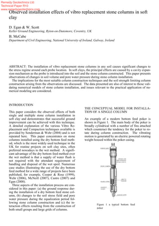
  • 1. INTRODUCTION This paper considers the observed effects of both single and multiple stone column installation in soft clay and demonstrates that successful ground improvement can be achieved with this technique. A detailed explanation of the various Vibro Re- placement and Compaction techniques available is provided by Sonderman & Wehr (2004) and is not repeated here. This paper concentrates on stone columns installed using the dry bottom feed meth- od, which is the most widely used technique in the UK for routine projects on soft clay sites, often preferred nowadays to the wet method. A signifi- cant advantage of the dry bottom feed method over the wet method is that a supply of water flush is not required with the attendant requirement of handling and disposal of the wet spoil. Numerous case studies illustrating the use of the dry bottom feed method for a wide range of projects have been published, for example, Cooper & Rose (1999), Wehr (2006), McNeill (2007), Castro (2007) and Egan (2008). Three aspects of the installation process are con- sidered in this paper: (a) the ground response dur- ing the installation of a dry bottom feed stone col- umn, (b) changes to the soil stress field and pore water pressure during the equalization period fol- lowing stone column construction and (c) the in- teraction effects resulting from the construction of both small groups and large grids of columns. THE CONCEPTUAL MODEL FOR INSTALLA- TION OF A SINGLE COLUMN An example of a modern bottom feed poker is shown in Figure 1. The main body of the poker is broadly cylindrical with a number of fins attached which counteract the tendency for the poker to ro- tate during column construction. The vibrating motion is generated by an electric powered rotating weight housed within the poker casing. Observed installation effects of vibro replacement stone columns in soft clay D. Egan & W. Scott Keller Ground Engineering, Ryton-on-Dunsmore, Coventry, UK B. McCabe Department of Civil Engineering, National University of Ireland, Galway, Ireland ABSTRACT: The installation of vibro replacement stone columns in any soil causes significant changes to the stress regime around each probe location. In soft clays, the principal effects are caused by a cavity expan- sion mechanism as the probe is introduced into the soil and the stone column constructed. This paper presents observations of changes in soil volume and pore water pressure during stone column installation. The implications for the most suitable column construction techniques and the soil strength limiting column construction arising from the observations are discussed. The data presented are also of interest to those vali- dating numerical models of stone column installation, and issues relevant to the practical application of nu- merical modeling are considered. Figure 1 a typical bottom feed poker Remedy Geotechnics Ltd Technical Paper R10 www.remedygeotechnics.com
  • 2. The stone is fed to the base of the poker body and compressed air flush is used to assist the stone delivery. The air flush, which is channeled to the bottom end of the poker, assists in creating a small annulus between the poker and the ground, reduc- ing frictional drag. The air flush also counteracts the suction that the poker would generate as it is withdrawn from the base of the column back up the bore, and which could lead to the surrounding soil moving back into the previously created void. The electrical current drawn by the poker dur- ing initial penetration of the ground and subse- quent compaction of the stone provides an indica- tion of the strength and stiffness of the ground. Figure 2 compares the measured draw of electrical current plotted against depth during the construc- tion of a 5.5m long column in soft alluvial clay. Also shown is the profile of undrained shear strength from the site (estimated from cone pene- tration test data). The increase in current draw with increase of the undrained shear strength of the host soil is clear. As there are a number of other factors which can affect the current draw of the poker it is not possible to develop a simple and universal rela- tionship with soil strength. However the ability to measure and record the current consumption does offer a qualitative indication of the quality of col- umn construction in soft soils where overworking of the ground (a sign of poor workmanship) should be avoided. This is one of the reasons why modern dry bottom feed rigs, fitted with advanced instru- mentation, can be used where hitherto the wet sys- tem would have had to be adopted. As the poker is lowered into the ground the soil is mainly displaced laterally as a cavity is opened up. Some vertical smearing of the soil adjacent to the poker may occur, although there is little evi- dence that this is significant, and some vertical heave of the ground surface can result. The magni- tude of heave is highly dependent on the arrange- ment of columns being constructed as discussed below. HEAVE Most experienced practitioners are aware that the installation of stone columns into soft clay can generate a degree of surface heave, particularly if construction control is inadequate and overworking of the ground takes place. Some degree of surface heave during the installation of stone columns us- ing the dry bottom feed method is inevitable and demonstrates that the stress regime around the col- umn is being altered and improvement of the ground is being achieved and is not detrimental to the final foundation performance. For this reason heave is rarely measured (indeed it is not necessary to do so). Nonetheless the few case studies where heave was recorded are of interest as they show that the amount of heave is a function of the col- umn size, spacing, extent and construction method. Castro (2007) reported a conical zone of surface heave with a maximum value of 290mm following the installation of a test group of seven columns. 0 0.5 1 1.5 2 2.5 3 3.5 4 4.5 5 5.5 6 0 25 50 75 100 125 Amps (A) Depth(m) 0 0.5 1 1.5 2 2.5 3 3.5 4 4.5 5 5.5 6 0 20 40 60 80 100 120 140 160 180 200 Cu (kPa) Depth Figure 2. Poker current demand compared with un- drained shear strength Figure 3. Stone column and instrumentation lay- out reported by Castro (2007) Remedy Geotechnics Ltd Technical Paper R10 www.remedygeotechnics.com
  • 3. The columns were 0.8m in diameter, 9.0m long in- stalled at 2.8m centres through soft to firm alluvial clay by Keller Terra in Spain. Figure 3 shows the column layout and the locations of piezometers in- stalled prior to the stone column construction. It is unclear if the heave reported was a local maximum and the overall volume of heave was not reported. Watts et al (2000) reported different amounts of heave for different column densities in the soft Carse clay at the Bothkennar test site in Scotland. (Details of this site are fully discussed in Geotech- nique, Volume 42, 1992). The columns were in- stalled to a length of 6m using a Bauer HBM4 bot- tom feed rig. The installation procedure followed the now dated practice of ramming a large volume of stone into the base of the columns creating an enlarged toe of up to 1.25m diameter. Extensome- ters revealed that most heave was generated by the construction of the bulb, emphasising that this practice is to be avoided if heave is to be con- trolled. No heave was recorded for two columns located at 1.5m centers (although 150mm of lateral displacement was measured by inclinometer 0.5m from the columns). Three columns at 2.0m centers produced an average local increase in ground sur- face of 107mm; four columns at 1.5m centers pro- duced an average of 143mm of heave. A maximum of 425mm heave was recorded due to installation of 25 columns 6m long to support an 8.1m square concrete test raft. The total volume of heave rec- orded for these 25 columns equated to 27% of the stone introduced into the ground. Measurements of heave have also been made during a few contracts performed by Keller Ground Engineering in the UK. In Contract A in Lincolnshire, an average of around 150mm of sur- face heave was measured during the installation of a large grid (80m x 70m) of 5m long 450mm di- ameter columns in soft alluvial clay (20kPa<Cu<50kPa, 30%<w<70%). The columns were installed on a 2m by 2m square grid and the volume of heave equated to 75% of the volume of stone in the columns. In another contract (Contract B), three separate rows each comprising five col- umns (550mm diameter and 5.5m long) were in- stalled in Carse clay. Contours of the average magnitude of heave, estimated from a grid of lev- els taken around each column group, are shown in Figure 4. The average maximum heave was around 70mm along the centreline, diminishing with dis- tance from the columns. In this case, the volume of heaved ground was estimated to be approximately 35% of the volume of stone installed in the col- umns. While the phenomenon of heave is occa- sionally referred to in the literature, very little quantitative guidance is available to estimate how much heave can be expected for any given column arrangement. Defining the Perimeter Ratio P and Heave Ratio Hp according to equations [1] and [2] below ap- pears to allow a relationship to be developed, and values of P and Hp are shown in Table 1 for the case histories discussed above. (1) Hp = Volume of heaved ground (2) Volume of stone columns Reference Number of columns in group Column length Average column diameter Arrangement Perimeter ratio, P Heave percentage, Hp m mm % Castro (2007) 7 9 800 2.8m spacing 1.05 12 Watts et al (2000) 8.1m raft 2 Columns 3 Columns 4 Columns 25 2 3 4 6 6 6 6 940 940 940 940 1.5m centers around edge of raft 5 in centre - - - 2.28 0.99 0.99 1.21 27 0 3 5 Keller Contract B 5 5.5 550 Single line 1.5m cen- ters 0.63 35 Keller Contract A ‘Infinite’ 5 450 Infinite 2m square grid 6.6 75 grouptheofperimeterExternal groupainperimetersColumn P Table 1. Data on observations of heave during column installation Remedy Geotechnics Ltd Technical Paper R10 www.remedygeotechnics.com
  • 4. The data from Table 1 are plotted in Figure 5 and while it is recognised that the database is limited the data shown an interesting trend suggesting some sort of relationship between column layout and amount of heave exists. Further collection of field data is recommended so that this relationship can be substantiated. Heave Summary It is clear from a number of observations that the process of constructing stone columns causes some lateral and vertical soil displacement, and that the proportion of lateral to vertical strain is a function of the lateral confinement of the host ground and adjacent stone columns. Single columns, rows and small groups of columns exhibit less vertical heave than large grids of columns. It also appears that that the closer the column spacing for any given column arrangement the greater the magnitude of heave. In considering these data, variations in ground conditions and installation practice be- tween different sites is not considered and at this stage and the trends shown in Figure 5 should be considered indicative rather than definitive. TOTAL STRESS AND CAVITY EXPANSION The penetration of the vibro poker into the ground and subsequent charging and compaction of the stone aggregate may be modelled mathematically by the theory of cylindrical cavity expansion, such as that developed by Gibson and Anderson (1961). As the process of stone column installation is rela- tively quick in saturated soft clays, undrained cavi- ty expansion is most applicable. Cavity expansion theory comes in various forms, taking account of (i) the required rigour in modelling soil behaviour (elastic, elastic-plastic or critical state solutions), (ii) whether the medium is finite or infinite, and (iii) the effect of various initial radii on the cavity stresses. Using Gibson and Anderson’s (1961) elastic- plastic theory, the zone of soil closest to the cavity is in a plastic state and the soil beyond remains in an elastic state. The radial extent of the plastic zone, R, may be calculated as: (3) where p is the cavity pressure r is the radial total stress at radius r, cu is the undrained shear strength and a is the radius of poker. Cavity expansion is effectively infinite in the case of a penetrating poker (starting from zero initial radius and expand- ing to radius a), in which case it is reasonable to assume that the pressure in the cavity will have reached the limit pressure (plim), calculated accord- ing to: (4) where ho, E and are the free field horizontal to- tal stress, Young’s modulus and Poisson’s ratio re- spectively. In this instance, the radial stresses in the plastic (r<R) and elastic (r>R) zones will be given by equations [5] and [6] respectively: (5) (6) -6 -5 -4 -3 -2 -1 0 1 2 3 4 5 6 -4 -3 -2 -1 0 1 2 3 4 -6 -5 -4 -3 -2 -1 0 1 2 3 4 5 6 -4 -3 -2 -1 0 1 2 3 4 Figure 4. Contours of heave around a line of stone columns )1(20lim u uh c E cp u r c p aeR 2 R r cc uuhr ln20 2 0 r R cuhr Figure 5 Ground surface heave ratios for stone column installation. Surface Heave Ratios 0% 10% 20% 30% 40% 50% 60% 70% 80% 0.00 1.00 2.00 3.00 4.00 5.00 6.00 7.00 Perimeter ratio HeaveRatio% Small groups Largegrid 8.1mRaft Remedy Geotechnics Ltd Technical Paper R10 www.remedygeotechnics.com
  • 5. The above equations were used to calculate the stress field at 2m depth for Contract B. At this site the clay was very soft with an undrained shear strength, cu, of around 10kPa at this depth. The stress field is shown in Figure 6, from which it can be observed that the radius of the plastic zone is 1.4m, beyond which the mean horizontal stress is unchanged from the initial (pre-column installa- tion) values. PORE PRESSURES AND CAVITY EXPAN- SION Observations During Column Construction Kirsch (2003), Gab et al (2007) and Castro (2007) measured the pore pressure response to the instal- lation process in three separate studies. Figure 7 reproduces the data shown by Castro (2007) as an example of the general trends. In all three cases the pore pressure rose extremely rapidly as the poker first penetrated the ground generally reaching a peak when the probe achieved the same depths as the piezometer. This is in keeping with general trends observed for displacement piles (i.e. McCa- be et al 2008). Sharp and significant fluctuations in readings characterise the curves during column construction and are attributed to a range of causes including contact pressure fluctuations as the poker is raised and lowered into the ground (low fre- quency), cyclic vibrations from the poker (high frequency ~50Hz), possibly effects from escape of air flush into the ground and general consruction vibration. In all cases the pore pressures reached a quasi static level, albeit at an elevated level, immediately after completion of each stone column. Subse- quent installation of adjacent columns leads to a further increase in the quasi static levels. Dissipation of the excess pore pressure is ob- served, occurring at different rates, governed by the permeability characteristics of the host soil. Kirsch (2003) and Castro (2007) do not provide dissipation data beyond the end of construction of the column groups and it should be noted that the columns appear to have been constructed in a high silt content soil so may not be directly comparable to stone columns constructed in soft clay. Castro (2007) presents a finite difference analysis to esti- mate the rate of drainage, however the measured Figure 7. Pore water pressures measured during stone col- umn construction (Castro (2007) Figure 6. Stress field around a stone in soft Carse clay StressDistribution Around an Expanded Cavity in Undrained Cohesive Soil 0 20 40 60 80 100 120 0 0.5 1 1.5 2 2.5 3 3.5 4 4.5 5 Radius(m) Stress(kPa) srdistribution throughout sq distribution throughout Meannormalstressin horizontalplane,sm RaplochData Series5 Castroformulation RaplochSite5FootingTrial 0 5 10 15 20 25 30 35 40 45 50 55 60 65 70 28-Aug 04-Sep 11-Sep 18-Sep 25-Sep 02-Oct 09-Oct 16-Oct 23-Oct 30-Oct Date Pressure(Pa) FootingB2mdepth FootingC2mdepth FootingA2mdepth FootingC4mdepth Column construction Construct footing Load footing Figure 8 Piezometer response to column loading Keller Carse clay site Keller Contract B Remedy Geotechnics Ltd Technical Paper R10 www.remedygeotechnics.com
  • 6. dissipation was approximately 10 times faster than predicted by the theory. This was attributed to the presence of ground fractures caused by the pene- tration of the air flush during column installation creating preferential drainage paths, but the actual reasons were not conclusively proved. Following Column Construction Figure 8 shows the dissipation of measured pore pressures from Keller Ground Engineering Con- tract B. The piezometers were BAT-System in- struments (supplied by BAT Geosystems AB) and comprise a porous filter tip which is inserted into the ground independently of the measuring sensor which can be inserted and removed from the filter tip many times and without causing any ground disturbance. To prevent possible damage to the measuring sensors, they were removed from the filter tips during stone column construction, being replaced immediately construction was completed. The pore pressures measured therefore are those prevailing just after completion of the stone col- umns. Figure 8 also shows the response of the pore water pressures over the following two months. It should be noted that a concrete footing was con- structed and then loaded as shown in Figure 8, be- fore full dissipation of the installation excess pore water pressure had occurred. Oedometer tests car- ried out on samples of the Carse clay indicated that 0.6<Cv<1.7m2 /yr and from insitu measurements 1.3<Ch<7.0m2 /yr. Watts et al (2001) report for the installation of 25 columns for a 8.1m square raft at the Bothkennar test site, a maximum 100kPa rise in pore water pressure during column construction, from a piezometer 5.0m deep installed midway be- tween 2 columns 1.5m apart. The elevated pressure appears to have dropped back to around 30kPa within 24 hours and had returned to pre-treatment levels after about 2 months. However some ele- vated pressure apparently remained between two columns at a depth of 5m after four months, alt- hough it is not clear why this was the case. Relevance of Observations to Cavity Expansion Theory Castro (2007) applies the Randolph et al (1979) formulation of cavity expansion theory applied to the installation of stone columns, suggesting that the increase in pore pressure at a radius r, is related to the undrained shear strength cu, and radius of the plastic zone (R) by: (7) A very good correlation with measured peak in- creases in pore water pressure at varying distance during the installation of a single stone column is shown. Installation of subsequent columns did not follow the theory at all well. It is probable that the changes in the soil stress field and pore water pres- sure distribution generated by installation of the first column violate the assumptions governing the cavity expansion theory formulation applied for in- stallation of subsequent columns. The curve from equation 7 is plotted in Figure 7 arising from the expansion of a 550mm diameter cavity 5.5m long plotted with measured pore water pressures for Keller Ground Engineering Contract B. A reasonable correlation is observed at a depth of 2.0m midway between two columns. Implications of Pore Pressure Changes The increase and then decrease of pore pressures arising from column installation indicate that the ground is squeezed laterally as the columns are in- stalled, causing an immediate undrained increase in pore water pressure which then dissipates as the clay consolidates and gains strength. From the published evidence the consolidation process ap- pears to take within a period of a few weeks fol- lowing column installation, during which time the ground between the columns increases in strength. This process will usually be complete before con- struction of the supported structure starts, or at least have concluded during the early stages of construction – the evidence being successful com- pletion over many years of a large number of vibro replacement projects in soft clays. IMPLICATIONS FROM OBSERVED BEHAV- IOUR FOR NUMERICAL MODELLING While the installation of bored piles can be sim- ulated in Finite Element packages such as PLAX- IS, there is currently no satisfactory procedure available to model the large lateral displacements associated with pile driving or stone column instal- lation. Some simple attempts to capture expected changes in ground properties have been proposed, although there is great uncertainty regarding how the ground responds as high quality field data that is sufficiently extensive is limited. Some ap- proaches that have been taken include: (i) increasing K0 in the vicinity of the columns to reflect the permanent increase in total stress )ln(2 r R cu u Remedy Geotechnics Ltd Technical Paper R10 www.remedygeotechnics.com
  • 7. (ii) Guetif et al (2007) model installation in PLAXIS 2-D by defining a cylinder of ‘dummy material’ with purely elastic proper- ties and a nominal Young’s Modulus (E=20kPa). The dummy material is then ex- panded from an initial diameter of 0.5m to a final diameter of 1.1m, before the properties of the ‘dummy material’ are converted into those of the column material. However, this approach appears to be unsuitable for PLAXIS 3-D as its basis is in small strain theory and numerical instability/inaccuracy may arise from large element distortions. (iii) Prompted by experimental results, Kirsch (2003) starts with a cylindrical block having the properties of stone, before applying a ra- dial expansion. He also suggests that the stress increase may be modelled by applying a temperature gradient to the stone column having a coefficient of thermal expansion, or the application of a strain or stress field to the finite element mesh. However the cavity expansion approach was deemed to be supe- rior from a numerical stability point of view. The key issue in modelling cavity expansion in a FE framework is the amount of radial strain that must be applied in the model to replicate field con- ditions, and importantly, whether this amount of expansion violates the assumptions in the FE theo- ry used. There is considerable amount of field work and model development that needs to be car- ried out in tandem before installation effects can be included in routine design. CONCLUSIONS The observed effects of stone column installation indicate that they improve the strength and stiff- ness of the host ground by a combination of intro- ducing granular elements of greater strength and stiffness than the host ground. Additional benefit is derived as a function of increasing the horizontal stresses and subsequent consolidation and increase in the strength of the host ground. Simple closed form equations based on cavity expansion are use- ful for modeling the increases in horizontal stress and pore water pressure rise due to the installation of a single column. Where groups of columns are installed interaction of the stress fields from each column occurs in a way that can not, at present, be described by simple closed form equations. While there has been fairly widespread use of numerical modelling for both research and project purposes, few studies have addressed the installation effects. Within the few numerical studies that have ad- dressed installation effects different modeling ap- proaches have been adopted and at the present time there does not appear to be a universally accepted, rigorous, means of accounting for the installation effects. What is clear is that installation effects can influence the performance of vibro replacement stone column projects, and as is the case with most geotechical processes, construction control by ex- perienced practioners remains the key to successful implementation. REFERENCES Castro 2007. Pore pressure during stone column installation, Proceedings of the 18th European Young Geotechnical En- gineers Conference, Ancona: Italy Cooper, M.R. and Rose, A.N. 1999. Stone column support for an embankment on deep alluvial soils. Proceedings of ICE Geotechnical Engineering, Vol. 137, pp 15-25. Egan, D. 2008 CPT Testing for the design and Implementa- tion of vibro replacement ground improvement. Proc. 3rd International Conference on site characterisation. Taipei: China. Gäb, M., Schweiger, H.F., Thurner, R. and Adam, D. 2007. Field trial to investigate the performance of a floating stone column foundation. Proceedings of the 14th European Con- ference on Soil Mechanics and Geotechnical Engineering. pp1311-1316. Madrid: Spain. Geotechnique, Volume 42, 1992. Gibson, R. H. and Anderson, W. F 1961. In-situ measure- ment of soil properties with Pressuremeter. Civil Engineer- ing and Public works review. Vol. 56. No. 658, May. Guetif, Z., Bouassida, M. and Debats, J.M. 2007. Improved soft clay characteristics due to stone column installation, Computers and Geotechnics, Volume 34, Issue 2, March 2007, pp. 104-111. Kirsch, F. 2003. Vibro Stone Column Installation and its ef- fect on ground improvement. McCabe, B.A., Gavin, K.G. and Kennelly M. 2008. Installa- tion of a reduced scale pile group in silt, Proceedings of the 2nd BGA International Conference on Foundations, Dun- dee. McNeill, J. A 2007. Improvement of Soft Ground by vibro stone columns. Proc. Conference on soft ground engineer- ing. Long, Jennings & Rutty (ed) Geotechnical Society of Ireland. Dublin: Ireland. Randolph, M.F. Carter, J.P. & Wroth, C.P. 1979. Driven piles in clay – the effects of installation and subsequent consolidation. Geotechnique 29 (4): pp361-393. Sondermann, W & Wehr, W, 2004. Deep vibro techniques. Ground Improvement. 2nd Edition Ed. Moseley and Kirsch. Watts, K. S, Chown, R. C & Serridge, C. J. 2001. Vibro- stone columns in soft clay: A trial to study the influence of column installation on foundation performance. Proc 15th Int Conf SM&GE. Vol 13: pp 1867-1870. Wehr, J 2006. The undrained cohesion of the soil as a crite- rion for the column installation with a depth vibrator. Transvib 2006. Genin, Holeyman & Rocher-Lacoste. (ed) LCPC. Paris: France. Remedy Geotechnics Ltd Technical Paper R10 www.remedygeotechnics.com