This document summarizes the methodology for lengthening a tuna fishing vessel. The vessel was lengthened by cutting it at 13.5 meters from the bow and inserting a 6.5 meter long block. This increased the overall length by 18% and the hull volume and cargo capacity by 20% and 55% respectively. Curves showing righting arms and flooding length were generated for the vessel before and after lengthening. Resistance curves were also generated. Calculations were provided to check that structural requirements were met after lengthening.
International Journal of Engineering Research and Development (IJERD)IJERD Editor
journal publishing, how to publish research paper, Call For research paper, international journal, publishing a paper, IJERD, journal of science and technology, how to get a research paper published, publishing a paper, publishing of journal, publishing of research paper, reserach and review articles, IJERD Journal, How to publish your research paper, publish research paper, open access engineering journal, Engineering journal, Mathemetics journal, Physics journal, Chemistry journal, Computer Engineering, Computer Science journal, how to submit your paper, peer reviw journal, indexed journal, reserach and review articles, engineering journal, www.ijerd.com, research journals,
yahoo journals, bing journals, International Journal of Engineering Research and Development, google journals, hard copy of journal
2001 iabse - Reliability Assessment of Cable-Stayed BridgesFranco Bontempi
IABSE Conference on Cable-Supported Bridges
June 12–14, 2001, Seoul, Korea
The paper deals with the reliability assessment of P.C. cable-stayed bridges, but it is thought that the presented methodology is generally applicable. Due to several sources of uncertainties, the geometrical and mechanical properties which define the structural problem cannot be considered as deterministic quantities. In this work, such uncertainties are modelled by using a fuzzy criterion which considers the model parameters bounded between minimum and maximum suitable values.
The reliability problem is formulated in terms of safety factor and the membership function over the failure interval is derived for several limit states by using a simulation technique. In particular, the strategic planning of the simulation is found by means of a genetic optimisation algorithm and the structural analyses are carried out by taking both material and geometrical non-linearity into account. An application to a cable-stayed bridge shows the effectiveness of the proposed procedure.
An Offshore supply vessel is a multi-task vessel and has to be designed for many different purposes. This is contrary to most other ships used worldwide. In general, the geographical location where the offshore activity takes place is an important indicator of the choice of supply vessel.
Factors like weather conditions, the amount of equipment needed and the distance from the shore
are important for what properties the vessel should have. The deep-water oilfield market is
becoming more important as the conventional oilfield market in shallow water cannot meet the
energy requirements from the consuming market. The Offshore Supply Vessels (hereafter it is
called OSVs) market is becoming booming and the demand for OSVs has never reached the extent
like today in previous periods.
In this project an offshore supply vessel will be designed according to ABS Rules.
Ring or circular rafts can be used for cylindrical structures such as chimneys, silos, storage tanks, TV-towers and other structures. In this case, ring or circular raft is the best suitable foundation to the natural geometry of such structures. The design of circular rafts is quite similar to that of other rafts.
Experimental Analysis on Sinking Time of Littoral Submarine .docxnealwaters20034
Experimental Analysis on Sinking Time of Littoral Submarine
in Various Trim Angle
Luhut Tumpal Parulian SINAGA1,a*
1Senior Researcher at PTRIM, BPPT Laboratorium Hydrodinamika Indonesia, Surabaya
[email protected]
*corresponding author
Keyword: Littoral submarine, dive, sink, experiment.
Abstract. A submarine must conform to Archimedes’ Principle, which states that a body immersed
in a fluid has an upward force on it (buoyancy) equal to the weight of the displaced fluid,
(displacement). Submarines are ships capable of being submerged. The history of submarines and
their operation have largely revolved around being able to alter the density of the vessel so that it
may dive below the surface, maintain a depth, and return to the surface as needed. The way modern
submarines accomplish this task is to bring in and remove water from tanks in the submarine called
ballast tanks. Ballast tanks fit into two categories: those used for major adjustment of mass (main
ballast tanks); and those used for minor adjustments (trim tanks). The effect of each tank is plotted
and this is compared with the changes in mass and trimming moment possible during operations
using a trim polygon to determine whether the ballast tanks are adequate. On the water surface,
metacentric height (GM) is important, whereas below the surface it is the distance between the
centre of buoyancy and the centre of gravity (BG) which governs the transverse stability of a
submarine.
Introduction
A submarine or a ship can float because the weight of water that it displaces is equal to the
weight of the ship. This displacement of water creates an upward force called the buoyant force and
acts opposite to gravity, which would pull the ship down. Unlike a ship, a submarine can control its
buoyancy, thus allowing it to sink and surface at will [1].
As with any object in a fluid, a submarine must conform to Archimedes’ Principle, which states
that a body immersed in a fluid has an upward force on it (buoyancy) equal to the weight of the
displaced fluid, (displacement). This applies whether the submarine is floating on the water surface,
or deeply submerged [2, 3].
To control its buoyancy, the submarine has ballast tanks and auxiliary, or trim tanks, that can be
alternately filled with water or air (see Fig. 1). When the submarine is on the surface, the ballast
tanks are filled with air and the submarine's overall density is less than that of the surrounding
water. As the submarine dives, the ballast tanks are flooded with water and the air in the ballast
tanks is vented from the submarine until its overall density is greater than the surrounding water and
the submarine begins to sink (negative buoyancy) [4, 5].
A supply of compressed air is maintained aboard the submarine in air flasks for life support and
for use with the ballast tanks. In addition, the submarine has movable sets of short "wings" called
hydroplanes on the stern (back) that help to.
Experimental Analysis on Sinking Time of Littoral Submarine .docxrhetttrevannion
Experimental Analysis on Sinking Time of Littoral Submarine
in Various Trim Angle
Luhut Tumpal Parulian SINAGA1,a*
1Senior Researcher at PTRIM, BPPT Laboratorium Hydrodinamika Indonesia, Surabaya
[email protected]
*corresponding author
Keyword: Littoral submarine, dive, sink, experiment.
Abstract. A submarine must conform to Archimedes’ Principle, which states that a body immersed
in a fluid has an upward force on it (buoyancy) equal to the weight of the displaced fluid,
(displacement). Submarines are ships capable of being submerged. The history of submarines and
their operation have largely revolved around being able to alter the density of the vessel so that it
may dive below the surface, maintain a depth, and return to the surface as needed. The way modern
submarines accomplish this task is to bring in and remove water from tanks in the submarine called
ballast tanks. Ballast tanks fit into two categories: those used for major adjustment of mass (main
ballast tanks); and those used for minor adjustments (trim tanks). The effect of each tank is plotted
and this is compared with the changes in mass and trimming moment possible during operations
using a trim polygon to determine whether the ballast tanks are adequate. On the water surface,
metacentric height (GM) is important, whereas below the surface it is the distance between the
centre of buoyancy and the centre of gravity (BG) which governs the transverse stability of a
submarine.
Introduction
A submarine or a ship can float because the weight of water that it displaces is equal to the
weight of the ship. This displacement of water creates an upward force called the buoyant force and
acts opposite to gravity, which would pull the ship down. Unlike a ship, a submarine can control its
buoyancy, thus allowing it to sink and surface at will [1].
As with any object in a fluid, a submarine must conform to Archimedes’ Principle, which states
that a body immersed in a fluid has an upward force on it (buoyancy) equal to the weight of the
displaced fluid, (displacement). This applies whether the submarine is floating on the water surface,
or deeply submerged [2, 3].
To control its buoyancy, the submarine has ballast tanks and auxiliary, or trim tanks, that can be
alternately filled with water or air (see Fig. 1). When the submarine is on the surface, the ballast
tanks are filled with air and the submarine's overall density is less than that of the surrounding
water. As the submarine dives, the ballast tanks are flooded with water and the air in the ballast
tanks is vented from the submarine until its overall density is greater than the surrounding water and
the submarine begins to sink (negative buoyancy) [4, 5].
A supply of compressed air is maintained aboard the submarine in air flasks for life support and
for use with the ballast tanks. In addition, the submarine has movable sets of short "wings" called
hydroplanes on the stern (back) that help to.
Aircraft wing design and strength, stiffness and stability analysis by using...Mani5436
1.Constructed the wing of the selected aircraft using the different type of materials.
2.Created Solid works simulation numerical model and perform analysis.
3.Conducted the strength calculations according to strength, stiffness and stability Requirements.
4.Prepared work Drawings.
Implications of the Second Generation Intact Stability Criteria When Applied ...IJMERJOURNAL
ABSTRACT: To address the problems of dynamic stability failures, the International Maritime Organisation plan to supersede the intact stability criteria. The draft criteria have been applied to a New Zealand naval patrol vessel to aid in understanding the implication imposed by the revised criteria. This paper addresses how the criteria were applied to the vessel and presents the outcomes of the calculated vulnerabilities. A computational simulation was conducted for the broaching phenomenon using four possible phenomenon-inducing wavelengths. It was found that the patrol vessel broached by more than fifteen degrees over a seven second time period. Therefore, taking into account the simplifications of the analysis, the OPVs, like other vessels, could be deemed vulnerable to the surf-riding and broaching-to phenomenon for these given, operationally avoidable, encounter conditions. Further analysis is recommended when the draft criteria is finalised.
SEMS and MARITIME TRANSPORT
Ships and aircraft autopilots are electromechanical systems used to stabilize these structures from the horizontal, as well as navigation systems to keep the course or flight path. In the case of passenger ships the horizontal stability control is achieved by means of retractable lateral stabilisers and ballast.
Autopilots measure the degrees of inclination and displacement of the structures but do not measure the elasticity of said structures. Instead the SEMS system as well as the elasticity also measures all inclinations and displacements of the structure, as it would be in the case of the 6 motions that occur in a vessel, which are: 3 turning or inclination movements, and 3 displacement movements as to the following figures.
The requirement to provide balance for rotating systems is a vital component in ensuring long, reliable service. This document describes a graphical method that can be used to determine the out of balance forces of such a system and the correct size and position of the balance weight required to do this. A worked example of the method is shown.
Overview of the fundamental roles in Hydropower generation and the components involved in wider Electrical Engineering.
This paper presents the design and construction of hydroelectric dams from the hydrologist’s survey of the valley before construction, all aspects and involved disciplines, fluid dynamics, structural engineering, generation and mains frequency regulation to the very transmission of power through the network in the United Kingdom.
Author: Robbie Edward Sayers
Collaborators and co editors: Charlie Sims and Connor Healey.
(C) 2024 Robbie E. Sayers
Hybrid optimization of pumped hydro system and solar- Engr. Abdul-Azeez.pdffxintegritypublishin
Advancements in technology unveil a myriad of electrical and electronic breakthroughs geared towards efficiently harnessing limited resources to meet human energy demands. The optimization of hybrid solar PV panels and pumped hydro energy supply systems plays a pivotal role in utilizing natural resources effectively. This initiative not only benefits humanity but also fosters environmental sustainability. The study investigated the design optimization of these hybrid systems, focusing on understanding solar radiation patterns, identifying geographical influences on solar radiation, formulating a mathematical model for system optimization, and determining the optimal configuration of PV panels and pumped hydro storage. Through a comparative analysis approach and eight weeks of data collection, the study addressed key research questions related to solar radiation patterns and optimal system design. The findings highlighted regions with heightened solar radiation levels, showcasing substantial potential for power generation and emphasizing the system's efficiency. Optimizing system design significantly boosted power generation, promoted renewable energy utilization, and enhanced energy storage capacity. The study underscored the benefits of optimizing hybrid solar PV panels and pumped hydro energy supply systems for sustainable energy usage. Optimizing the design of solar PV panels and pumped hydro energy supply systems as examined across diverse climatic conditions in a developing country, not only enhances power generation but also improves the integration of renewable energy sources and boosts energy storage capacities, particularly beneficial for less economically prosperous regions. Additionally, the study provides valuable insights for advancing energy research in economically viable areas. Recommendations included conducting site-specific assessments, utilizing advanced modeling tools, implementing regular maintenance protocols, and enhancing communication among system components.
Welcome to WIPAC Monthly the magazine brought to you by the LinkedIn Group Water Industry Process Automation & Control.
In this month's edition, along with this month's industry news to celebrate the 13 years since the group was created we have articles including
A case study of the used of Advanced Process Control at the Wastewater Treatment works at Lleida in Spain
A look back on an article on smart wastewater networks in order to see how the industry has measured up in the interim around the adoption of Digital Transformation in the Water Industry.
About
Indigenized remote control interface card suitable for MAFI system CCR equipment. Compatible for IDM8000 CCR. Backplane mounted serial and TCP/Ethernet communication module for CCR remote access. IDM 8000 CCR remote control on serial and TCP protocol.
• Remote control: Parallel or serial interface.
• Compatible with MAFI CCR system.
• Compatible with IDM8000 CCR.
• Compatible with Backplane mount serial communication.
• Compatible with commercial and Defence aviation CCR system.
• Remote control system for accessing CCR and allied system over serial or TCP.
• Indigenized local Support/presence in India.
• Easy in configuration using DIP switches.
Technical Specifications
Indigenized remote control interface card suitable for MAFI system CCR equipment. Compatible for IDM8000 CCR. Backplane mounted serial and TCP/Ethernet communication module for CCR remote access. IDM 8000 CCR remote control on serial and TCP protocol.
Key Features
Indigenized remote control interface card suitable for MAFI system CCR equipment. Compatible for IDM8000 CCR. Backplane mounted serial and TCP/Ethernet communication module for CCR remote access. IDM 8000 CCR remote control on serial and TCP protocol.
• Remote control: Parallel or serial interface
• Compatible with MAFI CCR system
• Copatiable with IDM8000 CCR
• Compatible with Backplane mount serial communication.
• Compatible with commercial and Defence aviation CCR system.
• Remote control system for accessing CCR and allied system over serial or TCP.
• Indigenized local Support/presence in India.
Application
• Remote control: Parallel or serial interface.
• Compatible with MAFI CCR system.
• Compatible with IDM8000 CCR.
• Compatible with Backplane mount serial communication.
• Compatible with commercial and Defence aviation CCR system.
• Remote control system for accessing CCR and allied system over serial or TCP.
• Indigenized local Support/presence in India.
• Easy in configuration using DIP switches.
Explore the innovative world of trenchless pipe repair with our comprehensive guide, "The Benefits and Techniques of Trenchless Pipe Repair." This document delves into the modern methods of repairing underground pipes without the need for extensive excavation, highlighting the numerous advantages and the latest techniques used in the industry.
Learn about the cost savings, reduced environmental impact, and minimal disruption associated with trenchless technology. Discover detailed explanations of popular techniques such as pipe bursting, cured-in-place pipe (CIPP) lining, and directional drilling. Understand how these methods can be applied to various types of infrastructure, from residential plumbing to large-scale municipal systems.
Ideal for homeowners, contractors, engineers, and anyone interested in modern plumbing solutions, this guide provides valuable insights into why trenchless pipe repair is becoming the preferred choice for pipe rehabilitation. Stay informed about the latest advancements and best practices in the field.
Forklift Classes Overview by Intella PartsIntella Parts
Discover the different forklift classes and their specific applications. Learn how to choose the right forklift for your needs to ensure safety, efficiency, and compliance in your operations.
For more technical information, visit our website https://intellaparts.com
TECHNICAL TRAINING MANUAL GENERAL FAMILIARIZATION COURSEDuvanRamosGarzon1
AIRCRAFT GENERAL
The Single Aisle is the most advanced family aircraft in service today, with fly-by-wire flight controls.
The A318, A319, A320 and A321 are twin-engine subsonic medium range aircraft.
The family offers a choice of engines
Saudi Arabia stands as a titan in the global energy landscape, renowned for its abundant oil and gas resources. It's the largest exporter of petroleum and holds some of the world's most significant reserves. Let's delve into the top 10 oil and gas projects shaping Saudi Arabia's energy future in 2024.
Top 10 Oil and Gas Projects in Saudi Arabia 2024.pdf
analisis de embarcaciones 2
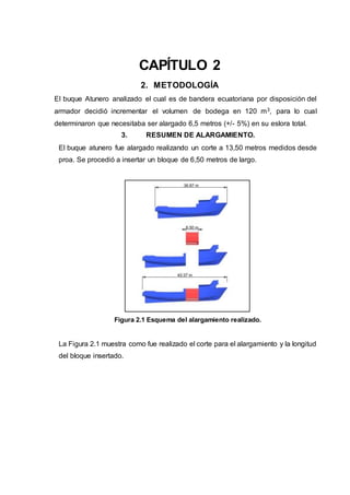
1. CAPÍTULO 2
2. METODOLOGÍA
El buque Atunero analizado el cual es de bandera ecuatoriana por disposición del
armador decidió incrementar el volumen de bodega en 120 m3, para lo cual
determinaron que necesitaba ser alargado 6,5 metros (+/- 5%) en su eslora total.
3. RESUMEN DE ALARGAMIENTO.
El buque atunero fue alargado realizando un corte a 13,50 metros medidos desde
proa. Se procedió a insertar un bloque de 6,50 metros de largo.
Figura 2.1 Esquema del alargamiento realizado.
La Figura 2.1 muestra como fue realizado el corte para el alargamiento y la longitud
del bloque insertado.
2. Tabla 2.1 Comparación de variación de dimensiones principales.
Características Principales Antes después variación
Eslora [m] 36,87 43,37 +18%
Manga [m] 8,25 8,25 0%
Punta [m] 3,87 3,87 0%
Volumen del casco [m3] 670,42 804,20 +20%
Capacidad de bodega [m3] 216,84 335,94 +55%
Capacidad de combustible [galones] 30090,00 29050,00 -3%
Potencia instalada [hp] 650 650 0%
tripulación 23 25 +9%
En los APÉNDICES se encuentran los planos de líneas de forma, capacidad de
combustible y capacidad de bodegas, donde se pueden visualizar las
modificaciones realizadas.
4. CRITERIOS DE ESTABILIDAD PARA BUQUES PESQUEROS
Del libreto de estabilidad proporcionado a nuestro patrocinador podemos obtener
las características necesarias para determinar la estabilidad del atunero en cada
condición de carga.
Tal como solicita la OMI, el libreto de estabilidad existente cuenta con las 3
condiciones de carga mínimas requeridas para buques pesqueros, estas son:
Salida de puerto: En esta condición de carga analizamos el buque con el 100% de
consumibles y 0% de pesca.
Media travesía: En esta condición de carga analizamos el buque con el 50% de
consumibles y 100% de pesca.
Llegada a puerto: En esta condición de carga analizaremos el buque con el 10% de
consumibles y 100% de pesca.
A continuación, mostramos las características del buque en cada condición.
Tabla 2.2 Características de carga de la embarcación sin alargar
Ligero Salida de puerto Media Travesía Llegada a puerto
3. Desplazamiento (Ton) 333,17 563,05 562,05 503,05
KG (m) 4,802 4,205 4,1 3,792
5. CURVA DE BRAZOS ADRIZANTES
Para obtener la curva de brazos adrizantes vs ángulo de escora utilizamos la
siguiente ecuación:
𝑩𝒓𝒂𝒛𝒐 𝑨𝒅𝒓𝒊𝒛𝒂𝒏𝒕𝒆𝒔 (𝑮𝒁) = 𝑲𝑵 − 𝑲𝑮 ∗ 𝑺𝒆𝒏(𝜽) (2.1)
Donde:
KN: Curvas cruzadas de la embarcación.
KG: En centro de gravedad vertical del buque, para cada condición de carga.
𝜃: El ángulo de escora analizado.
Figura 2.2 Curva de brazos adrizando para cada condición de carga. Buque sin
alargar.
En la Figura 2.2 se observa la curva de brazos adrizantes en cada una de las
condiciones de carga analizadas del buque antes del alargamiento.
6. CRITERIOS DE ESTABILIDAD BUQUE ALARGADO
7. Modificación del desplazamiento en ligero
Al momento del presente trabajo no se ha realizado una prueba de estabilidad del
buque, por lo que no es posible determinar de manera experimental el centro de
gravedad del buque, así como su desplazamiento. Por esta manera se calculará el
peso añadido de la estructura, eje y tuberías.
0.00
0.10
0.20
0.30
0.40
0.00 10.00 20.00 30.00 40.00 50.00 60.00
Gz(m)
Angulo de escora (grados)
Salida de puerto
Media Travesia
Llegada a puerto
4. Se conoce que los refuerzos del bloque insertado mantendrán la configuración
estructural inicial del buque, por lo que de los planos estructurales se verifico los
tipos de refuerzos y espesores, con esto podemos realizar el plano del bloque
insertado. En la Figura 2.3 observamos el esquema del bloque insertado en la
embarcación.
Figura 2.3 Esquema del bloque insertado,
En el APÉNDICE C, se muestra los detalles de los elementos estructurales de la
embarcación.
Considerando que el bloque insertado es de 6,50 metros y que la separación entre
cuadernas es de 50 centímetros podemos calcular el peso que tendrá el bloque
insertado ya que el material a utilizar es acero naval cuya densidad es de 7,80
toneladas/m3.
Tabla 2.3 Resumen de pesos añadidos.
Peso elementos longitudinales 23,48
Peso elementos transversales 6,48
Super estructura 6,50
tuberías [ton 3,00
Eje 6'' 3,70
Total, peso estructural [ton] 43,16
Para determinar cuánto se desplaza en centro de gravedad en sentido vertical es
necesario encontrar el centro de gravedad del bloque insertando. Esto se lo puede
5. calcular al ya conocer las características estructurales del mismo: En Anexos se
muestra la tabla del cálculo del eje neutro
EJE NEUTRO [m] 3,87
Una vez obtenido el eje neutro del bloque insertado, lo que resta por realizar es una
suma de momentos para así encontrar el nuevo centro de gravedad vertical siendo
estos 4,67 metros medidos desde la línea base.
8. Condiciones de carga del buque alargado
Una vez realizado los cálculos del peso en ligero, es necesario realizar determinar
las características de la embarcación una vez se llenen las nuevas bodegas.
Tabla 2.4 Características de carga del buque alargado
Condición
Ligero Salida Intermedio Llegada
Δ(Ton) 376,33 659,35 673,99 674,97
KG (m) 4,67 4,10 4,01 3,96
6. 9. Curva de brazos adrizantes:
De igual manera que para el buque sin alargar se debe realizar al buque alargado.
Figura 2.4 Curva de brazos adrizantes para cada condición de carga (Buque
alargado)
En la Figura 2.4 se observa la curva de brazos adrizantes en cada una de las
condiciones de carga analizadas del buque posterior al alargamiento.
10. ESLORA INUNDABLE
Para determinar la curva de eslora inundable utilizaremos un software el cual nos
permitirá realizar dicho calculo, para nuestro caso dicha herramienta será Maxsurf,
en el módulo Stability.
Dependiendo del compartimiento se debe considerar las siguientes
permeabilidades.
0
0.1
0.2
0.3
0.4
0.00 10.00 20.00 30.00 40.00 50.00 60.00
Gz(m)
Angulo de escora (grados)
Salida de puerto
Media travesia
Llegada a puerto
7. Tabla 2.5 Permeabilidades según zona del buque [Autor: SOLAS]
ESPACIO PERMEABILIDAD
Destinados a Carga 0,60
Acomodación 0,95
Maquinaria 0,85
Espacios Vacíos 0,95
Destinados para líquidos 0 or 95
11. ESLORA INUNDABLE DEL BUQUE SIN ALARGAR
Antes del alargamiento la embarcación contaba con 6 mamparos transversales, los
cuales proporcionaban estanqueidad a los compartimentos, a continuación, se
presenta la distribución de los mamparos estancos.
Figura 2.5 Esquema de ubicación de línea marginal y mamparos estancos. Buque
Atunero ´´A´´ sin alargar
La Figura 2.5 muestra la ubicación de cada compartimento estanco, así como la
línea marginal utilizada para el estudio.
Utilizando un software se determinó la curva de eslora inundable considerando 2
compartimentos continuos inundados:
8. Figura 2.6 Permeabilidad Buque Atunero ´´A‘Sin alargar
12. ESLORA INUNDABLE DEL BUQUE ALARGADO
Al realizar el alargamiento del buque se instaló un mamparo estanco adicional,
siendo la nueva distribución de mamparos la siguiente:
Figura 2.7 Esquema de ubicación de línea marginal y mamparos estancos. Buque
Atunero ´´A´´ alargado
Utilizando un software se determinó la curva de eslora inundable considerando 2
compartimentos continuos inundados:
9. Figura 2.8 Permeabilidad Buque Atunero ´´A´´ Alargado
13. RESISTENCIA AL AVANCE
Para calcular la resistencia al avance de la embarcación utilizaremos el software
MafSurf en el módulo Resistance. El método que utilizara el software es Holtrop.
14. RESISTENCIA AL AVANCE DEL BUQUE SIN ALARGAR
En la Figura 2.9 se observa la resistencia al avance generada por el casco sin
considerar el alargamiento del buque.
Figura 2.9 Resistencia al avance del buque Atunero ´´A´´ sin alargar
0
50
100
150
200
250
4 6 8 10 12 14 16 18
Resistencia
KN
Velocidad de avanceNudos
10. 15. RESISTENCIA AL AVANCE DEL BUQUE ALARGADO
En la Figura 2.10 se observa la resistencia al avance generada por el casco
considerando el alargamiento del buque.
Figura 2.10 Resistencia al avance del buque Atunero ´´A´´ alargado
16. RESISTENCIA ESTRUCTURAL
17. ESFUERZOS PRIMARIOS.
Como se mencionó con anterioridad los esfuerzos primarios son aquellos que se
consideran toda la estructura se flecta como una viga bajo distribución de carga
longitudinal (José Marin- 2016)
Para considerar los esfuerzos primarios DNV nos proporciona dos herramientas
que permiten medir que tan resistente es una embarcación: el mínimo modulo
seccional que debe tener el buque y los esfuerzos cortantes y momentos flectores
admisibles
18. Mínimo modulo seccional sin alargar
La sociedad de clasificación DNV, determina que el mínimo modulo seccional para
una embarcación viene dando por la siguiente ecuación:
𝑍𝑅−𝑔𝑟 = 𝐾 (
1+𝑓𝑟
2
)𝐶𝑤0𝐿2
𝐵(𝐶𝐵 + 0.7)10−6
(𝑚3) (2.2)
2.3)
Donde:
fr: Factor de reducción especificado en DNV RU-SHIP Par 3. Chapter 5
Cwo: 5,7+0,0222L
0
50
100
150
200
250
4 6 8 10 12 14 16 18
Resistencia
al
avance
KN
Velocidad de avanceNudos
11. L: eslora del buque.
B: Manga del buque
CB: Coeficiente de bloque del buque
K: Esfuerzo cortante permisible de acero utilizado/125
Tabla 2.6 Cálculo de mínimo modulo seccional: buque sin alargar
k 0,73
fr 1,00
Cwo 6,52
L [m] 36,87
B [m] 8,25
Cb 0,62
ZR-gr [m3] 7,08E-02
19. Mínimo modulo seccional alargado
De igual manera para determinar el mínimo modulo seccional del buque una vez
realizado el alargamiento es aplicable este método, donde el valor a modificar es el
de la eslora del buque.
Tabla 2.7 Cálculo de mínimo modulo seccional: buque alargado
k 0,73
fr 1,00
Cwo 6,66
L [m] 43,37
B [m] 8,25
Cb 0,63
ZR-gr [m3] 1,01E-01
20. Modulo seccional real del buque
Para el cálculo del módulo seccional deben incluirse únicamente los elementos
longitudinalmente continuos. Haciendo referencia a la Figura 2.3, donde se observa
el esquema del bloque insertado y al APÉNDICE C, donde se presenta el resumen
de los elementos estructurales del bloque podemos realizar calculo respectivo
mostrado en el APÉNDICE D.
12. 21. Esfuerzos secundarios.
El bloque por analizar es parte del bloque insertado, el cual forma parte de la
bodega de almacenamiento número 1. Para este análisis se utilizó el bloque
comprendido entre los mamparos transversales 2 y3. El cual tiene una eslora de
4,50 metros. El bloque se muestra en la Figura 2.11.
Figura 2.11 Esquema 3D del bloque insertado
22. Mínimos módulos seccionales.
Los mínimos módulos seccionales vienes dados por la siguiente ecuación según
DNV.
𝑍(𝑐𝑚3
) = 1000 ∗
𝑃𝑆𝑙2
𝑓𝑏𝑑𝑔 𝐶𝑠 𝑅𝑒𝐻
(2.3)
Donde:
Cs: 0,85
Fbdg: 24,00
l: la longitud no soportada del elemento analizado 0,50 m
P: presión de diseño (Considerando las fuerzas de presión externas consideradas
por DNV se obtiene: 37,24 kN/m2)
S: la separación entre refuerzos =0,85 m
ReH: 235 N/mm2
A continuación, se muestra los mínimos módulos seccionales según el tipo de
elemento.
13. Tabla 2.8 cálculo de Modulo seccional del buque.
Elemento Mínimo modulo seccional (cm3)
Longitudinales de Fondo 3,30
Transversales de fondo 69,91
Longitudinales de costado 1,94
Transversales de costado 63,10
Longitudinales de cubierta 3,30
Transversales de cubierta 95,16
23. ESFUERZOS TERCIARIOS
24. Mínimos espesores de planchas
El mínimo espesor que debe tener las planchas de fondo viene dado por la siguiente
ecuación:
𝑡 (𝑚𝑚) = 𝑎 + 𝑏𝐿√𝐾 (2.4)
Donde:
a= 4,5
b= 0,035
L: eslora del buque
K: 1
Obteniendo un espesor mínimo que debe tener las planchas de fondo de 6,02 mm.
Aplicando la misma ecuación tanto para las planchas de costados y cubierta
tenemos los siguientes espesores mínimos: 5,51 mm para costados y 5,36 mm para
cubierta.
25. ANÁLISIS ECONÓMICO.
26. COSTO DE UN BUQUE NUEVO
Para poder realizar un análisis comparativo es necesario conocer cuál será el costo
de una embarcación nueva en el mercado actual de características similares. Como
bien es sabido la capacidad de bodega del Buque atunero ´´A´´ es de 335,94 m3.
Del proyecto realizado por el autor en la materia de Diseño de Buques que fue el
´´Diseño preliminar de un buque atunero de red de cerco con capacidad de 350 m3
de bodega. Podemos obtener información la cual nos ayuda a estimar el costo de
una embarcación nueva con características similares.
14. En el proyecto en mención se analizó el costo de los grupos constructivos: 100,
200, 300 y 600.
El costo referencial lo podemos observar en la siguiente tabla.
Tabla 2.9 Costo por Grupo de un buque atunero Nuevo con capacidad de 350 m3
de
bodega.
GRUPO COSTO POR GRUPO
100 $3 292 662,60
200 $511 960,00
300 $100 700,00
600 $94 750,00
APAREJOS $ 1 900 000,00
SISTEMA DE FRIO $85 000,00
COSTO REFERENCIAL $ 5 985 072,60
27. COSTO DE VENTA DEL BUQUE ANTES DE SER ALARGADO.
Otro referente para poder realizar un análisis económico es tener el costo
referencial si la empresa desea vender el Buque Atunero ´´A´´ en su condición
actual, es decir antes de realizar el alargamiento, se realizará un avalúo de la
embarcación.
El objetivo del avalúo es determinar un valor, entendiéndose este, como la
estimación del valor económico de un bien. (N. Hidalgo – 2013)
El método utilizado para el avalúo estará basado en ingeniería de Tasaciones.
Para determinar el valor de costo actual de una embarcación a la fecha que se
efectúa la tasación utilizaremos la siguiente ecuación:
𝑉𝐶𝐴 = 𝑉𝑅𝑁 ∗ 𝐹𝐷 ∗ 𝐹𝑀 ∗ 𝐹𝑂 (2.5)
Donde:
VCA: Valor de costo actual
VRN: Valor de reposición nuevo
15. FD: Es el factor de depreciación ingenieril. =𝐹𝐷 =
𝑉𝑈𝑃 −𝐸
𝑉𝑈𝑃
VUP: Valor de vida útil probable
E: es la edad del bien
FM: Es el factor de mantenimiento
FO: Es el factor de obsolescencia.
Factor de mantenimiento: Este valor representa la calidad de mantenimiento que
se pudo observar durante la inspección. Estos valores se los determina utilizando
la siguiente tabla:
Tabla 2.10 Factor de Mantenimiento. Fuente (N. Hidalgo – 2013)
Características del Mantenimiento F.M.
Mantenimiento preventivo 0,9 1,0
Mantenimiento Correctivo 0,8 0,9
Mantenimiento Deficiente 0,7 0,8
Factor de obsolescencia: Representa el valor por la obsolescencia funcional y
económica. Es decir, la perdida por reducción de la demanda, reducción de
materias primas, calidad inferior del producto y, por la disminución de utilidades La
calidad del producto está relacionada con la calidad de la mano de obra, el deterioro
físico de la maquinaria tecnológica incorporada o utilizada en el proceso. (N.
Hidalgo, H.F. Rodas -2009). Este factor se puede determinar con la siguiente tabla:
Tabla 2.11 Factor de obsolescencia. Fuente (N, Hidalgo - 2013)
Edad (Años) F.M.
1 5 0,85 0,99
6 10 0,75 0,84
11 15 0,65 0,74
21 25 0,55 0,64
25 mas 0,45 0,54
Esto se lo realiza para cada sistema de la embarcación como se detalla en la
siguiente tabla con el avalúo correspondiente:
El avalúo del buque es el siguiente: $1 251 985,04, el resumen del avalúo se
observa en APÉNDICE F.
16. 28. COSTO DEL ALARGAMIENTO DEL BUQUE ATUNERO
Los trabajos de alargamiento realizados al Buque Atunero ´´A´´ se efectuaron en la
ciudad de Guayaquil, en un varadero privado. La estadía total de la embarcación
fue de 90 días. Durante los cuales se realizaron los trabajos de corte y soldadura
del casco, mantenimiento general al casco de la embarcación, arena y pintura del
casco, reemplazo de ánodos de zinc.
El costo total del mantenimiento fue de: $489 392.50, el resumen de trabajos se
puede observar en el APÉNDICE E.
29. COSTO OPERATIVO ANUAL
En esta sección separaremos los costos operativos en dos grupos, los costos fijos,
los cuales son independientes del número de faenas anuales y a su vez del tonelaje
de captura en cada faena y en costos variables los cuales dependerán del número
de faenas realizadas por la embarcación y por el tonelaje capturado.
Los costos fijo más relevantes del buque son los sueldos de la tripulación,
mantenimiento predictivo, preventivo, seguros y diques.
Los costos variables son los del consumo de combustible y bonos a pescadores.
Al año se deben considerar los 60 días de veda, que en estas fechas se aprovecha
para que las embarcaciones realicen trabajos de mantenimiento y dique. La faena
por lo general dura 45 días además a esto hay que considerar 5 días de carga y
descarga. Lo que nos permite tener como máximo 6 faenas anuales.
30. Gastos independientes de la captura de atún.
Considerando que todos los tripulantes de la embarcación (sin alargar) cuentan con
contratos de trabajo ellos reciben sueldos base mensuales, el cual da un total de
$201 600,00. El resumen de estos gastos de observan en el APÉNDICE G.
Además, la embarcación realiza trabajos de dique cada dos años los cuales tienen
valores promedio de $ 70 000,00 lo que implican $35 000,00 anuales.
Como se menciona en la tabla 2.12, la embarcación sin alargar tenía capacidad de
30 090 galones de Diesel, considerando que en cada faena el combustible es
17. consumido en su totalidad, así mismo, actualmente el valor comercial del galón de
Diesel es de $1,30. Lo que representa un costo anual de $234 702,00.
Al considerar los mismos gastos para el buque alargado existen modificaciones en
ciertos gastos los cuales depende del número de tripulantes y capacidad de
combustible. A continuación, se detallan los gastos fijos de la embarcación:
Tabla 2.12 Resumen de gastos fijos
31. Gastos dependientes a la captura de atún
Para poder realizar un análisis económico cercano a la realidad es necesario
plantearnos posibles escenarios de captura, para lo cual en base al historial de
captura del buque atunero ´´A´´, tenemos que recordar que la capacidad máxima
de carga de atún de la embarcación está restringida, ya que si se llevase
completamente cargada la embarcación esta superaría el calado máximo
permisible, por tal razón solo puede ocupar 262,98 m3 de su total. Los escenarios
considerados son los siguientes:
Escenario ideal: Es en escenarios se considera 6 de 6 viajes con la máxima
captura.
Escenarios Normal: En este escenario se considera 3 viajes con 100% de la
captura 2 viajes con 50% de la captura y 1 viaje con 25% de la captura.
Escenario Real: En este escenario se considera 4 viajes con 75% de captura y 2
viajes con 50% de captura.
Escenarios Crítico: En este escenario se considera 4 viajes con 50% de la carga
y 2 viajes con el 10% de la carga.
Tabla 2.13 Comparativa de toneladas anuales capturadas en diversos escenarios.
Toneladas de atún capturado anualmente
Escenario Buque sin Alargar Buque Alargado
Gastos independientes de la captura (anual)
Buque sin alargar Buque Alargado
Sueldo fijo de tripulantes $201 600,00 $211 200,00
Mantenimiento $35 000,00 $65 000,00
Diesel $234 702,00 $217 875,00
Víveres $8 000,00 $9 200,00
Total $479 302,00 $503 275,00
18. Ideal 1105,88 1341,20
Normal 755,69 916,49
Real 737,26 894,13
Critico 405,49 491,77
En esta sección consideraremos la bonificación por tonelada que recibe cada
tripulante.
Tabla 2.14 Bonificación según el rango del tripulante por tonelada de atún
capturado.
RANGO PAGO ($/ton)
Capitán Pescador 25
Patrón Costanero 25
Marinero de Puente 15
Marinero Pescador 15
Marinero de máquinas 1 12
Marinero de maquinas 12
Aceitero 12
Timonel 12
Panguero 12
Cocinero 12
Pescador 12
Tabla 2.15 Comparativa de bonificaciones anuales (buque sin alargar- Buque
alargado)
Bonificación tripulantes ($)
Escenario Buque sin Alargar Buque Alargado
Ideal $347 247,58 $421 136,17
Normal $237 285,84 $287 776,38
Real $231 498,38 $280 757,45
Critico $127 324,11 $154 416,60
32. INGRESOS ANUALES
Para determinar los ingresos debemos conocer el costo de venta de la tonelada de
atún en el mercado ecuatoriano. Que durante los últimos años ha mantenido un
valor promedio de $ 1 600,00 por tonelada. (El comercio- 2020)
19. A continuación, presentamos los ingresos que tendría la embarcación en cada
escenario.
Tabla 2.16 Comparativa de ingresos del buque (alargado- Sin alargar)
Ingresos del buque ($)
Escenario Buque sin Alargar Buque Alargado
Ideal $1 769 414,40 $2 145 916,80
Normal $1 209 099,84 $1 466 376,48
Real $1 179 609,60 $1 430 611,20
Critico $648 785,28 $786 836,16