This document provides an introduction to steam generators and their components. It discusses various boiler design considerations including construction types, available fuels, coal ash characteristics, and combustion technology selection. Key points include:
- Boilers can be shop assembled package units, field assembled modular units, or fully field erected units. The type selection depends on size, firing type, and life cycle costs.
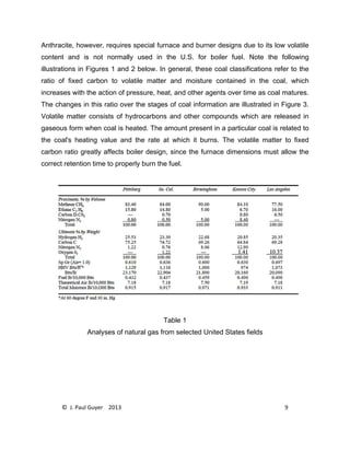
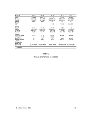
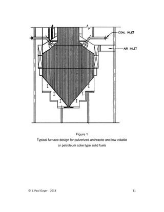
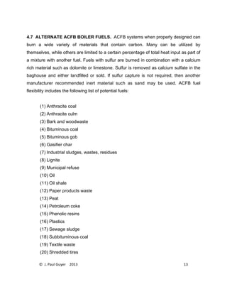
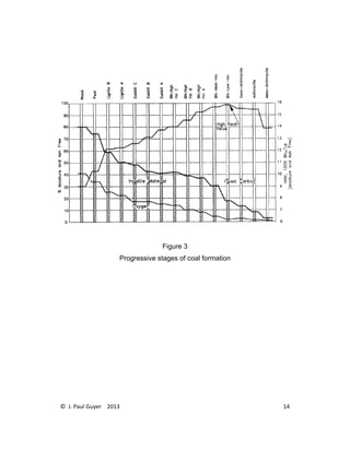
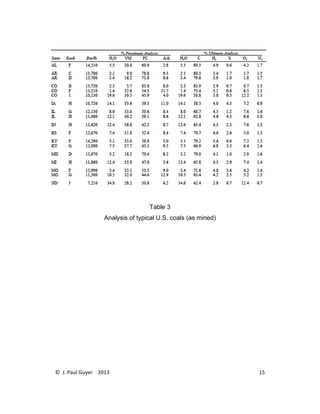
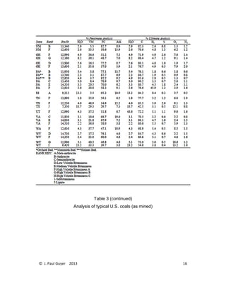
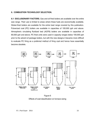
- Available fuels include natural gas, fuel oils, coal, and various alternative fuels for atmospheric circulating fluidized bed boilers. Coal is classified based on its composition and heating value.
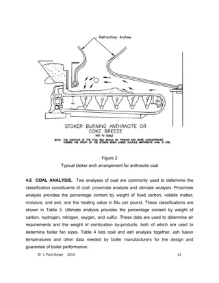
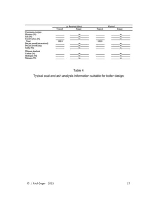
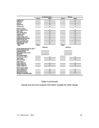
- Coal ash characteristics like fusion temperature influence slagging and fouling potential and must be considered in furnace design. Ash analysis is important for selection of

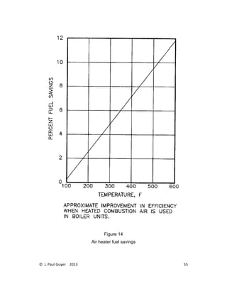
![© J. Paul Guyer 2013 24
When rapid load swings are expected, stoker-fired units may be eliminated because of
their inferior response to these conditions. When economics dictate the use of low
grade fuels including those of high or variable ash content or high sulfur content then
stoker-fired and PC systems may be eliminated in favor of ACFB systems. If none of
these firing systems are excluded by these factors, then the choice between firing
systems must be made on the basis of a life cycle cost analysis (LCCA).
6.2 BASE CAPITAL COST. The base capital cost of a dual firing system is the total
price of purchasing and installing the entire system, including the boiler, furnace, either
stoker, pulverizer or fluidization system, fans, flues, ducts, and air quality control
equipment. PC fired and ACFB boilers are more expensive than stoker-fired boilers of a
given capacity, in part because they have a larger furnace to provide space and time for
the combustion process to go to completion. Approximately 60 to 90 percent of the ash
content of the coal passes through the unit along with the gases of combustion. Tube
spacing within the unit has to be provided in order to accommodate this condition and
the ability of this ash to cause slagging and fouling of the heating surface. These factors
can increase the size of the boiler and its cost. PC fired units have been replaced by
packaged boilers in capacity ranges below 100,000 pph. Gas, oil and PC boilers require
a flame failure system which increases their cost. The total cost of an ACFB boiler
addition is offset by not requiring flue gas desulfurization (FGD) or selective catalytic
reduction (SCR). Selective noncatalytic reduction (SNCR) is required on ACFB boilers
in place of SCR.
6.3 AVERAGE BOILER DUTY. The remaining expenses calculated for an LCCA are
all functions of the average boiler duty. This value is based on the estimated annual
boiler load during the expected life of the plant. It is calculated as follows:
[average load (pph)/rated capacity] x [hours of operation/8760 hours] = average boiler duty](https://image.slidesharecdn.com/anintroductiontosteamgeneratorsr1-221222230356-6a44765a/85/An-Introduction-to-Steam-Generators-R1-pdf-25-320.jpg)