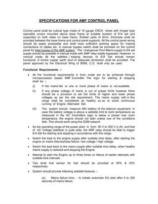
The control panel specifications require a cubical panel made of 16 gauge sheet metal with hinged covers to house the control components above a base frame. Rubber pads will isolate the base frame from the panel supports. A manual bypass switch and earth stud shall be provided. The panel must achieve automatic control of an engine-alternator set through a microprocessor-based controller in auto mode, including starting the engine on mains failure and stopping it on restoration based on voltage and timing settings. Alarms and operational parameters shall be transmitted to a remote monitoring station via GSM modem using GPRS or SMS.

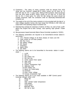
![h) DG fail to stop
i) Overload
j) Fuel low
k) Fuel very low (for stopping of engine)
l) BTS battery low
m) DG battery low
n) DG fault (common for any DG fault)
o) Canopy door open
p) Fire Alarm
q) Canopy temperature high
r) Low water level (for water cooled sets)
s) Over / Under voltage
t) Over / Under frequency
Operational Requirement
i. AC and DC wiring shall be separated distinctly.
ii. Connections of control wiring shall be done with connector strips and ferrules for
identification on both ends.
iii. 1No. Multifunctional meter to indicate Voltage, Current, PF, Frequency & kWh of
DG Set.
iv. Push button for stop, reset, and acknowledge.
v. Recess type hooter.
vi. Audiovisual indication for LLOP, HCT / HWT, Over speed, Lack of fuel.
vii. RYB LED indication for indicating Mains / EA Set Supply – 2 sets.
viii. DC Ammeter [0-15A], DC Voltmeter [0-30V] of size (min.72mmx72mm )with
selector switch for trickle charging through battery charger and battery charging
unit
ix. Selector switch for Auto /Manual operation .
x. Battery Charger: Automatic trickle battery charger of SCR or SMPS type to
charge the starting battery of DEA set. This charging shall be done through main
supply for which a suitable incomer shall be provided in the panel with suitable
range of ammeter and voltmeter on the DC side with protective fuses.
SAFETY CONTROL TRIP
(i) Low lubricating oil pressure.
(ii) High cylinder / water temp.
(iii) Lack of fuel.
(iv) Alternator Fault
(v) Over speed
(vi) Fire Alarm
Note :- Latest test report from any NABL accredited laboratory for protection
against EMI / RFI is required to be submitted along with the application.](https://image.slidesharecdn.com/amfspecs14-07-08-120901062102-phpapp02/85/Amf-specs-14-07-08-4-320.jpg)