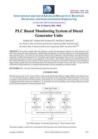
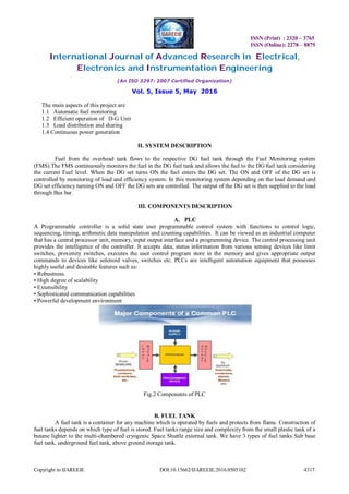
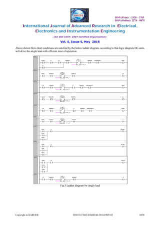
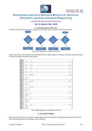
This document describes a PLC-based system for monitoring diesel generator units. Key aspects of the system include automatic fuel level monitoring of the diesel tanks, efficient operation and load distribution of the generator units. The system uses sensors to monitor fuel levels and a PLC to control solenoid valves to refill the tanks automatically. Ladder logic is used to implement control strategies for efficient single or combined load operation. When implemented, this system would allow for automated maintenance and operation of diesel generator units without human intervention.
![ISSN (Print) : 2320 – 3765
ISSN (Online): 2278 – 8875
International Journal of Advanced Research in Electrical,
Electronics and Instrumentation Engineering
(An ISO 3297: 2007 Certified Organization)
Vol. 5, Issue 5, May 2016
Copyright to IJAREEIE DOI:10.15662/IJAREEIE.2016.0505102 4322
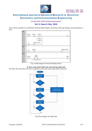
Fig.8 Complete Model showing Operation of Fuel Tank and DG Units
VI. CONCLUSION
Generation control is the important aspect of any power generation system. Several methods can be
implemented to control the generator in power plant. This project helps in maintaining of diesel generator units
efficiently by monitoring fuel level optimally, efficient time of operation of DG units, efficient load sharing, accurate
operation of plant using PLC.
REFERENCES
[1] P.K.Bhowmik, M. Dey, and S. K. Dhar, “PLC Based Operation and Control of Two Diesel Generator Set”, Department of Electrical &
Electronic Engineering, Chittagong University of Engineering & Technology.
[2] P.K.Bhowmik and M. Dey,“Protection and Control of Steam Turbine Generator using PLC” First International Conference on Mechanical
Engineering and Renewable Energy.
[3] Monitoring of Electro-mechanical System, "Diesel – Synchronous Generator" Alexander Gasparjan, Alexander Terebkov Latvian Maritime
Academy, LMA, Riga, Latvia
[4] Load Compensation for Diesel Generator-Based Isolated Generation System Employing DSTATCOM Bhim Singh, Fellow, IEEE, and
Jitendra Solanki, Member, IEEE
[5] S. Da'na, A. Sagahyroon, A. Elrayes, A.R. Al-Ali, R.Al-Aydi “Development of a monitoring and control platform for PLC-based
applications”
[6] Tadao Nakamura, Oyama, Japan,“Automatic load distributing apparatus for generator and method of controlling same”
[7] Diesel Generator Operation Guideline, Reactor Operation an Maintenance Unit (ROMU) of Bangladesh Atomic Energy Commission.
[8] Y Jaganmohan Reddy, Y V Pavan Kumar, K Padma Raju, Anilkumar Ramsesh, “PLC Based Energy Management and
Control Design for an Alternative Energy Power System with Improved Power Quality”, International Journal of
Engineering Research and Applications
[9] Anoop R, Anup J Nambiar, Prathap R, Sridhar Divakar, Dr. T B Isha Sucosoft PC Based Condition Monitoring of a Diesel – Generator Set.
[10] S. Boopathi, M. Jagadeeshraja, L. Manivannan, M. Dhanasu -“Smart Generator Monitoring System in Industry Using Microcontroller”](https://image.slidesharecdn.com/02d7d684-8cfa-4152-adbf-78abafaa51ae-160627062141/85/102_19_PLC-7-320.jpg)


