
Download to read offline
![Are we talking about a Virtual Reality system?
If we consider the table as just a humancomputer interface (like the mouse), and since the user is interacting with a computer
simulated physical system and can see the result of the interaction on the computer screen, we can say that we are in front of an
elementary example of a virtual reality system (featuring primarily realtovirtual world interaction, with visual feedback). The
immersion in the simulated environment is of course minimal (the screen), but we could enhance this by using stereo vision, head tracking
and a headmounted display.
Did you say Interaction Metaphor?
However, the interaction method suggests here that the virtual object actually sits on the real table; this is a compelling interaction
metaphor that facilitates the commanding of virtual objects. An interesting example of the use of such "gravity metaphor" (based on the
principle that virtual and real spaces are both affected by the real gravity field) is for instance text scrolling on a PDA [2].
Compelling and intuitive (or “natural”) interacting metaphors are important because the user already has knowledge and training that can
be applied to the new situation, thus reducing learning time and improving efficiently. An example of this, aimed at speeding up the use of
a graphical user interface (GUI) in a desktop computer, is the Parallax Augmented Display that I recently studied in my laboratory.
Mixed Reality? Augmented reality?
Now, the impression that the virtual ball is "there" can be enhanced if a projector is used to actually project the image of a ball on the table.
At this stage, we can also interpret the whole installation as an example of a mixed reality system: a virtual object "materializes" in the
real world and interacts with it (augmented reality is the combination of real and computer generated images, but an augmented reality
system is less concerned with the interaction between these worlds).
Although this "presence" is limited (here we only see a ghostly image) we could as well make a robotic avatar of the virtual object,
evolving in the real world and interacting with real forces…
But then, what have we got here? a virtual reality system? Certainly not. Mixed reality system? or is this just a REAL system (although the
"brains" of the robot may be sitting somewhere in a computer nearby?). This shows that these distinctions are arbitrary and tied to our
idiosyncratic understanding of complex systems in which we are a part. We are necessarily confronted to such philosophical questions
when we think about interaction design and physical computing. How important it is from the point of view of the designer to answer
these questions? It depends: for example, it may be very important if it helps clarify the underlying interaction metaphor).
II. Plan of the presentation
We will break the problem (and therefore the workshop time) in three parts:
A. Software . Simulation of a ball on the computer screen. This entitles interesting topics of simulation of physical processes
(classical problems in realistic video games).
B. Hardware: use Arduino platform to capture twoaxis acceleration data
C. Communication protocol: unidirectional without flow control / unidirectional with flow control for tight synchronization
(important in virtual reality systems). Bidirectional with flow control…
A. SOFTWARE](https://image.slidesharecdn.com/alvaroworkshopyotsuyaartschool-150401140931-conversion-gate01/75/Alvaro-workshop-yotsuya-art-school-2007-2-2048.jpg)

![divide operators interpret operands as being the same type of the more precise of them (see Appendix 2). So, to force things to
interpret as floats, we would do: 1.0*mouseX/2.
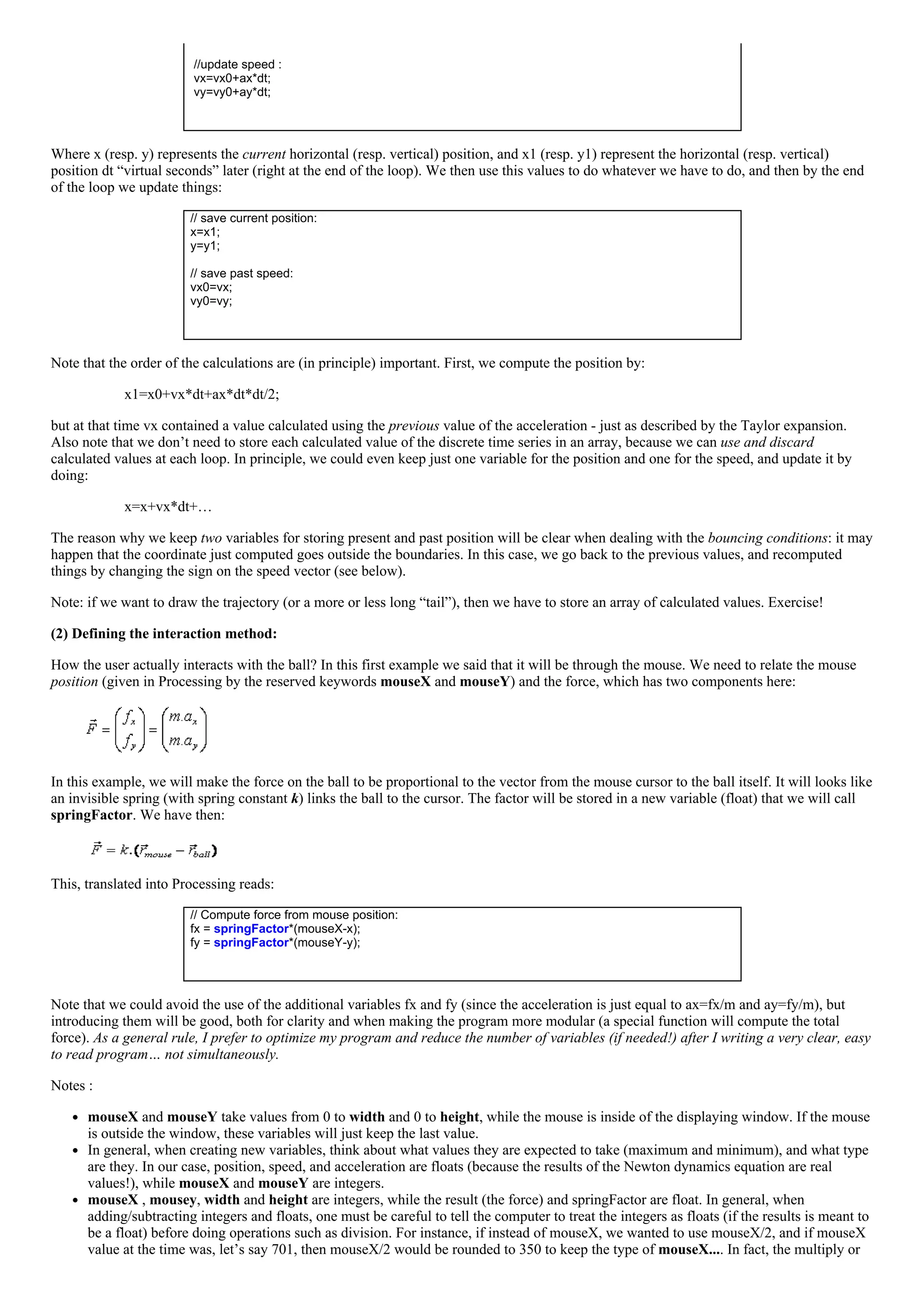
Simulation of the ball dynamic is almost complete. We just need to add the bouncing effect. Actually, as you can imagine, simulating a real
collision may be a very complex task involving knowledge of the ball and wall roughness, elasticity, shape, etc. In this simple example, we
will assume that the ball is a point of mass, and that the bouncing just changes the sign of the velocity component perpendicular to the
surface.
How? Very easy: right after computing the new position, check if either x or y position fall outside the virtual box boundaries, (for
instance, 0 to width and 0 to height). If it does, just change the corresponding speed component:
// Test boundary conditions:
if ((x<0)||(x>width)) {vx=0.98*vx; x1=x;};
if ((y<0)||(y>height)) {vy=0.98*vy; y1=y;};
…and avoid updating the current (x or y) position: that’s the role of the x1=x and y1=y, which will “cancel out” the update position lines
at the end of the loop.
Note : This situation actually corresponds to a process that conserves the kinetic energy of the ball. We can make things even more
realistic, by simulating the loss of kinetic energy (transformed in heat for instance). For this purpose, we added an “energy conservation
factor” when bouncing, in the example equal to 0.98 (do it really correponds to the energy conservation factor? exercise). Also, to make
your model even more realistic you could add viscosity/friction: just add a friction force proportional to the speed, but with opposite sign!
Exercise…
(3) Displaying the ball.
This is the easiest part, thanks to the very nature of Processing language. The software takes care of displaying things properly – uses a
double buffer and swap technique to avoid flickering, so it only display things when everything was drawn, never in the middle of the
process! So, after clearing the display, you can put the actual drawing commands pretty much anywhere in the loop (the relative order is of
course important when considering occlusion).
Basically, we just first clear the screen using the background(255) function (clear things to white), and then we draw the ball in its current
coordinates, for instance using the ellipse(x,y, rx, ry) function. The color can be set using the fill(R,G,B) function:
// clear the screen:
background(255)
// display the ball as a solid disc:
fill(0,0,250);
ellipse(x, y, ballRadius, ballRadius);
That’s it! Putting everything together in the SimulBall1.pde code:
// ===================================================================
// Name of program: SimulBall1.pde
// Language: Processing ver 0133
// Function: Simulation of a 2D bouncing ball "attached" to the mouse cursor
// through a springlike force.
// ===================================================================
// Author: Alvaro Cassinelli
// ===================================================================
// Versions: [14.11.2007] the initial program, without defining a ball "class"
// Global variables (here, the intrinsic variables of the ball among
// other things).
// ================================================================
float x, y, x1, y1;
float vx, vy, vx0, vy0;
float ax, ay;
float fx, fy;
float m;
float dt;
float springFactor=100.0;
float ballRadius=10;
void setup() {
// define size of the displaying screen:
size(700,500);
// initialize variables (in processing, this can be done during declaration)
x=width/2;
y=height/2; // start in the middle of the screen
vx=0;
vy=0;
vx0=0;
vy0=0;
m=0.01;
dt =0.002; // in “virtual” seconds (one loop takes dt).
springFactor=1.0;
ballRadius=15;](https://image.slidesharecdn.com/alvaroworkshopyotsuyaartschool-150401140931-conversion-gate01/75/Alvaro-workshop-yotsuya-art-school-2007-5-2048.jpg)
![ax=fx/m; ay=fy/m;
// update position :
x1=x+vx*dt+ax*dt*dt/2; y1=y+vy*dt+ay*dt*dt/2;
//update speed :
vx=vx0+ax*dt; vy=vy0+ay*dt;
// Test boundary conditions:
if ((x1<0)||(x1>width)) { vx=0.98*vx0; x1=x; };
if ((y1<0)||(y1>height)) { vy=0.98*vy0; y1=y; };
// Update the current position and past speed:
x=x1; y=y1;
vx0=vx; vy0=vy;
}
}
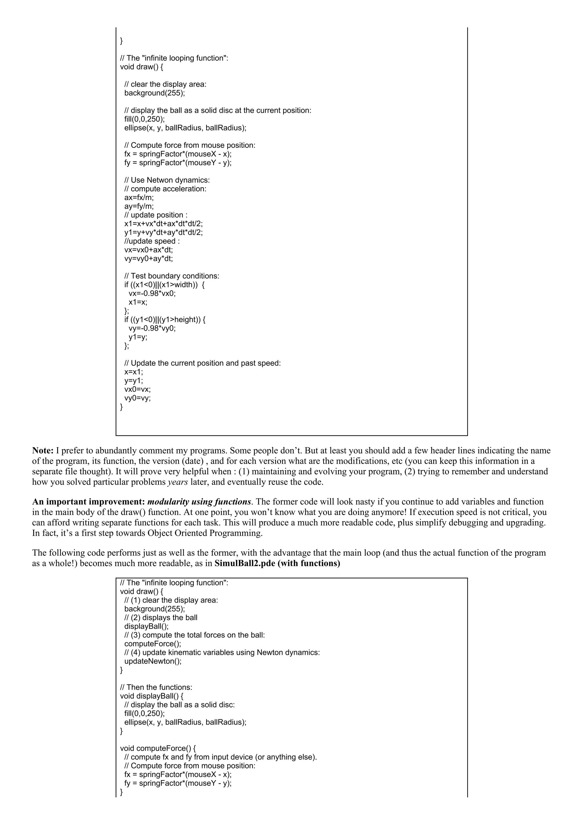
Some great things about object programming:
you can create (i.e. "instantiate") as many of these objects as you want.
code is reusable in other programs, and by other people, thanks to a proper documented "interface" (separate interface and
implementation files in C++)
Let’s see an example of the first advantage . Suppose that you want to create a hundred balls that evolve simultaneously on the screen.
Imagine that you code this as in the very first example (everything as global variables, and with or without functions): for each variable of
the ball, you will need to create now an array, and then in your program you will need to treat each ball sequentially, and take care of
sequentially addressing each variable for the corresponding ball. This is not incredible complicated in this example, but I bet that even in
this case you may make mistakes and scramble things easily. Look how easy it is to do the same using the Object Oriented Programming
paradigm (SimulBall4.pde, instantiating and using several objects simultaneously):
// Global variables: an ARRAY of particles, here 5
classBall[] ball=new classBall[5];
void setup() {
// define size of the displaying screen:
size(700,500);
//instantiate ALL the particles, one by one, with different positions, radius and masses
// rem: in this example, the radius is proportional to the mass (see the constructor!)
for (int i=0; i<5; i++) ball[i]=new classBall(random(0,width),random(0,height),random(0.01,0.09));
}
// The "infinite looping function":
void draw() {
// clear the display area:
background(255);
// now, for treat the balls sequentially:
for (int i=0; i<5; i++) {
// displays the ball with index i in the object array:
ball[i].displayBall();
// compute the total forces on the ball with index i in the object array:
ball[i].computeForce();
// update kinematic variables of ball with index i in the object array:
ball[i].updateNewton();
}
}
… and that’s all!! You don’t have to touch a thing in the class definition!! Beautiful, isn’it? That will do for our minimal incursion in the
fantastic world of object oriented programming..
B. Hardware:
Use Arduino/Wiring platform to capture information from a twoaxis acceleration data. I assume that you know how to acquire data using
the Arduino/Wiring platform. Here, we will just read two analog values from an accelerometer, so the code is extremely simple.](https://image.slidesharecdn.com/alvaroworkshopyotsuyaartschool-150401140931-conversion-gate01/75/Alvaro-workshop-yotsuya-art-school-2007-8-2048.jpg)
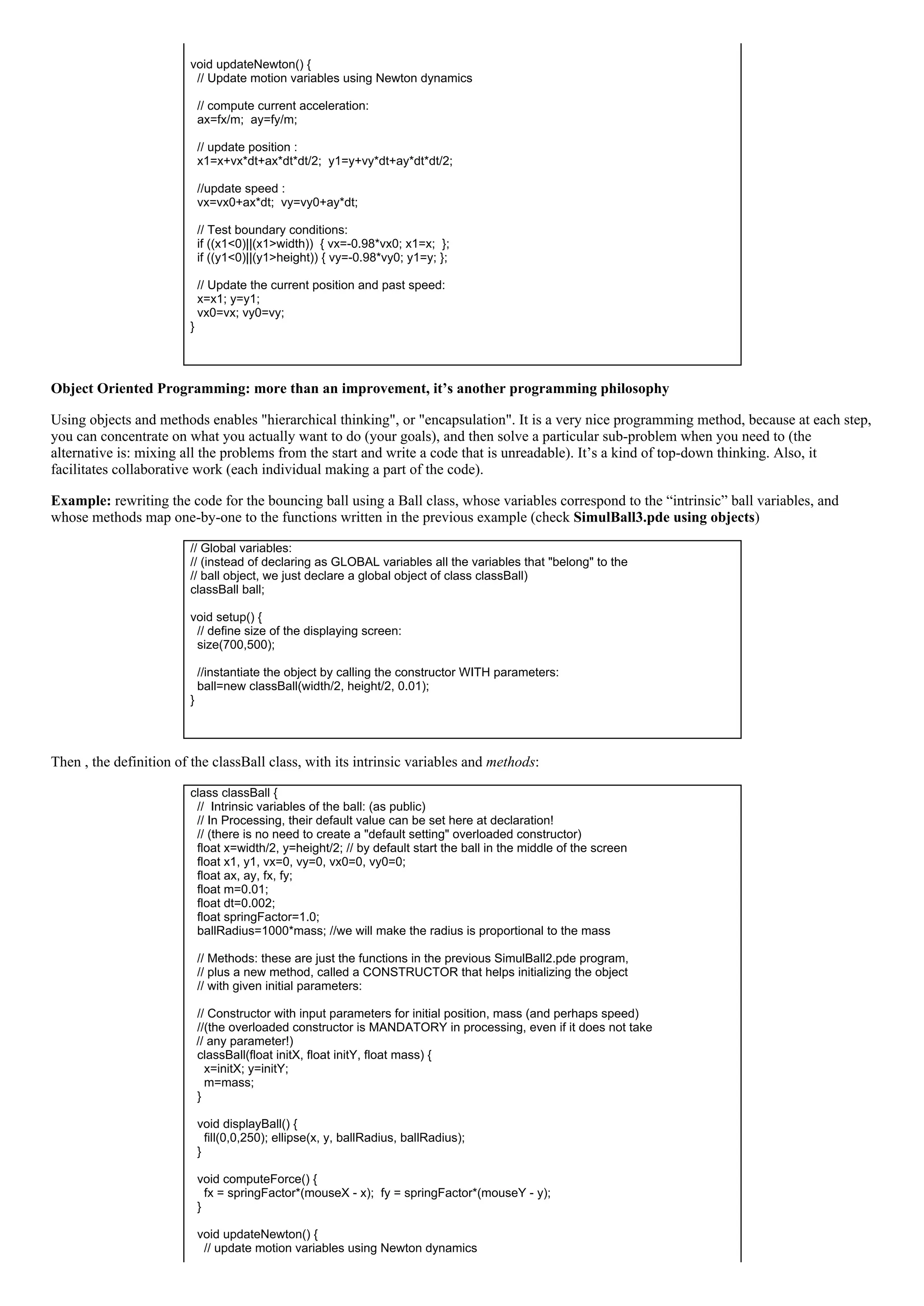
![Application / Presentation / Session / Transport / Network / DataLink / Physical
Keep in mind that the only real interest of this subdivision is to separate different communications subsystems to simplify
debugging/upgrading process (hardware and software), very much like when you program using functions (or objects). When
modifying one subsystem, if it performs exactly as specified by the OSI standards, then there is no need to touch anything in the rest of the
system.
In this workshop we will talk concentrate on serial communications (i.e., sending data one bit at a time over the communication channel).
Serial communication can be synchronous or asynchronous. Asynchronous serial communication is used in RS232, USB, FireWire, Midi ,
Ethernet…We will concentrate on this. Serial communication is a “lowlevel” protocol, and most certainly we won’t need to implement all
the OSI layer. A more adequate subsystem subdivision for implementing/debugging this communication protocol may be the following
(proposed in Tom Igoe’s fantastic book "Making things talk"):
Physical: connection pins (how many, how are they connected).
Electrical: electrical voltage levels used
Logical: mapping between voltage level and logical bit
Data: are bits sent in groups (frames) of bytes? Big or Little Endianness? Timing of bits? [OSI: transport layer / network layer and
data link layer].
Application: the thing that you really have to deal with! How the bits/bytes are arranged in messages? Packets? How you read and
interpret the packet data? Is there flowcontrol or not (handshake)?
Now, as you may know the Atmel microcontroller chip (in the Wiring/Arduino board) has two pins (RX/TX) and implements the TTL
Serial Protocol, while the modern PCs “speaks” USB serial! How they can communicate? Thanks to a serial to USB converter, that is
embedded in the Arduino/Wiring board (the “FTDI” USBtoSerial adaptor chip). Of course, if you use an old PC with an RS232
connector, then both side will be talking TTL serial, and you can directly connect the Arduino RX pin to the “receive” pin (pin 2) of the
RS232 connector, the TX pin of the Arduino to the “transmit” pin of the connector (pin 3), and the Arduino GND to the pin 5 of the
connector (the PC ground). If you use the USB based Arduino, which you probably do, then both sides are talking a slightly different serial
protocol:
Arduino side: TTL SERIAL
Physical: The Atmel microcontroller has two pins, labeled RX and TX for this. In the Arduino, these are digital pins 0 and 1 (if you
use the serial communication, you cannot use these pins for other purposes).
Electrical: electrical voltage levels: TTL (05V).
Logical: mapping between voltage level and logical bit: 0V = 0, 5V=1.
Data: the data rate can be set by the user (ex: 9600 bits/s), the unit of transmission is an 8 bits long frame (preceded by a start and an
end bit, but this is not seen by the application).
Application: from the Arduino side, you will use the following commands to write your own application layer communication protocol:
Serial.begin(speed)
int Serial.available()
int Serial.read()
Serial.flush()
Serial.print(data, format)
Serial.println(data, format)
I will explain each command during the workshop; but the most important thing to remember is that when you write (using Serial.print) or
read data (using Serial.read), you will read a data unit, which as we said is a group of 8 bits (so the “minimum” type of the variable to store
this data can be a char or a byte).
PC/MAC side: USB SERIAL
Physical: The Atmel microcontroller has two pins, labeled RX and TX for this. In the Arduino, these are digital pins 0 and 1 (if you
use the serial communication, you cannot use these pins for other purposes).
Electrical: electrical voltage levels: TTL (05V).
Logical: mapping between voltage level and logical bit: 0V = 0, 5V=1.
Data: the data rate can be set by the user (ex: 9600 bits/s), the unit of transmission is an 8 bits long frame (preceded by a start and an
end bit, but this is not seen by the application).
Application: from the MAC/PC side with Processing installed, you will use commands provided by the Serial library to write your
own application layer communication protocol. These commands are in fact methods of the Serial class:
Serial methods:
Serial,
available()
read()
readChar()
readBytes()
readBytesUntil()
readString()
readStringUntil()
buffer()
bufferUntil()
last()](https://image.slidesharecdn.com/alvaroworkshopyotsuyaartschool-150401140931-conversion-gate01/75/Alvaro-workshop-yotsuya-art-school-2007-10-2048.jpg)
![myString=trim(myString); // takes away the spaces and carriage return codes
//split the string at the commas (our packet delimiters) and convert the
// decimal, ASCII coded numbers into integers:
int data[] = int(split(myString, ','));
// check if we received all the data (we could have started from the second value...)
if (data.length==2) {
// assign the read value to the global force, using a special conversion function:
globalFx=convertData(data[0], 5000, 327, 263, 396);
globalFy=convertData(data[1], 5000, 326, 265, 403);
}
}
The conversion function is a very important function: it relates the real world measurements to the virtual world quantities. It’s a bridge
between worlds and you have to take care that it does the job properly. This means that you will need to experiment quite a bit until you get
the right values for the conversion (it can be just a linear operation involving an offset and a gain, but it can also imply logarithms and
perhaps much more complicated operations, which may involve knowledge on psychophysics for instance). In our case, we will do just a
basic linear operation:
// convert the value read from the accelerometer to the force on the ball:
float convertData(int value, float gain, int offset, int minvalue, int maxvalue) {
float force;
force=1.0*gain*(valueoffset)/(maxvalueminvalue);
return(force);
}
The arguments to the function are respectively the Gain factor, the offset (i.e., the value measured when the accelerometer is horizontal for
instance), then the minimum and maximum sensor readout. You can check all these values by opening the serial monitor in the Arduino
IDE and trying different positions for the accelerometer. However, in advanced versions of this program you could do this work
automatically, and/or display these values on the Processing window.
Note: even if you perform some calculations beforehand, you will need to adjust the parameters to get the “best looking / best feeling”
dynamics and interaction. This is an extremely important (and sometimes time consuming) phase. Don’t overlook it! The nice thing about
it (as well as when you are coding your program for the first time and make unexpected errors) is that you can also discover new
possibilities, and get new ideas you didn’t think about before. Be alert, and don’t miss what the computer (bugs) may bring you as a gift!
Finally, change the way the acceleration is calculated for each ball in the updateNetwon method of the class classBall, by using the global
variable forceFx and forceFy:
// compute current acceleration, using the GLOBAL FORCE:
ax=globalFx/m;
ay=globalFy/m;
B) Unidirectional communication with flow control (Handshake)
In fact, this application protocol implements an unidirectional communication without flow control. If you try the complete system
Arduino+Processing (try it!), you may notice some random delays between the action and the response in the virtual environment. The
reason (one of the reasons at least) is that we have overlooked the fact that the Arduino board can continuously sends data at a sufficiently
high pace, and if Processing does not read (because it cannot or don’t need to) these bytes at the same rate, then the serial buffer (at the PC
side) may be filled until it is full and bytes sent by the Arduino board will be lost. Even if loosing some bytes is not important (this may be
the case if the unit of information you are sending is a byte), Processing may be reading data that is a little outdated (the serial buffer in the
PC side is a couple thousand bytes long) .
The solution is to implement a form of flowcontrol known as handshake (or synchronous communication) between both sides. In it’s
simplest form, the handshake protocol is: only send data when the Processing program actually request it! (check SimulBall6.pde). First,
we will define a binary flag (i.e. a Booleantype variable) to make the program “remember” if it has sent a request, and if this request has
been answered. If not, then don’t issue a new request (but don’ wait! Just ignore things and continue drawing the balls):
// a FLAG to avoid sending request if we didn't receive a (complete) answer yet
boolean can_Talk=true;
Then, add somewhere in the guts of the draw function the following code:
// send a request to read sensor data (only if we "can talk" again, because we already
// diggested the complete answer from the microcontroller!
if (can_Talk==true) {
can_Talk=false;
serialPort.write(10); // just send anything (here a carriage return...)](https://image.slidesharecdn.com/alvaroworkshopyotsuyaartschool-150401140931-conversion-gate01/75/Alvaro-workshop-yotsuya-art-school-2007-13-2048.jpg)
![}
Finally, when the request has been answered, we have to reset the flag to true, meaning that we will now be able to issue new requests.
This is done by modifying the serialEvent function, and setting can_Talk flag to true if the answer from the microcontroller was complete
and well received:
…
// now, check if we actually received all the data! (we could have been reading from the second
value...)
if (data.length==2) {
// assign the read value to the global force, using a special conversion function
globalFx=convertData(data[0], 5000, 327, 263, 396);
globalFy=convertData(data[1], 5000, 326, 265, 403);
// if we got here, it means that the answer was complete and well received;
// we can reset the can_Talk flag to true, so we can issue new requests:
can_Talk=true;
}
…
It’s not over: we still have to “enslave” the Arduino microcontroller, making the program less talkative and more obedient. The Arduino
must only send data to the serial port when the Processing program send s a request code (here anything on the serial buffer). This is very
simple; we just need to check if something is in the serial buffer ( readHandShake.pde). This is done adding these few commands in the
middle of the Arduino loop:
//Send values through the serial port when requested:
if (Serial.available()>0) {
sendData();
Serial.read(); // we have to clear at least ONE byte (= one request!)
}
… and then you can also get rid of the delay(100): if things go as planned, the serial buffer (at the PC side) will never be overloaded!
Video demo of the (almost) finalized project (click here or on the images below to launch video):
� �
Where to go from here?
…Of course, wherever you want to! I hope I’ve given you a taste of how easy it can be to create some compelling interactive system. But
here you have some ideas for developing this prototype system:
Games: make a game out of this. For example:
involving two participants. Goal: very much like the airpuck, but with tilting control.
another possibility is to draw small circles/dots at particular locations that will confine the ball if the inclination is not very
large, and try to get all the balls on the dots; or avoid some dots where the ball can fall; or move them around a labyrinth
without touching the walls, etc.
Interactive painting machine: instead of representing the ball, use nicer graphics, such as “field forces” around the center of the
particles that could interfere: you will get very interesting Moir� motifs that will change as you move the table. Or trace the
trajectories of the particles, etc.
Interface for musical expression: control panning of sound using ball position and four speakers: then, from a mixed reality system
we create now a HUMAN COMPUTER INTERFACE. Why this can be a good idea? Because the human readily interpret the
"virtual object" motion and interact with it as if it were real but for the fact that it will have some "magic" consequences, such as
controlling sound.
Conclusion & Comments:](https://image.slidesharecdn.com/alvaroworkshopyotsuyaartschool-150401140931-conversion-gate01/75/Alvaro-workshop-yotsuya-art-school-2007-14-2048.jpg)
![Many tutorials end by the words “get creative”. I find this a little curious since if you are here now, it means that you have (or had) at least
some ideas that you want (or wanted) to implement; I mean, it’s good to learn how to interconnect things and “get inspired” by the hands
on workshop, but this may not always lead to the idea up there! Of course it can be pleasurable to do some hacking, but it may be a little
frustrating to end up doing again thelittlerobotthatwalksandbumpsintothewalls, and that’s it! (it only impresses you because you
know what’s “inside” I know what I am talking about! ;). Seriously, I encourage you to think first about what you want to do, play with
the idea for a while in your mind, eventually talk with other people and always think as if the implementation was not a problem. Think
without limits during that phase. If your idea resist brainstorming (and/or evolve from them), then it may be worth putting all your energy
on it!
… and once you are at it, don’t think too much: just do it. If you keep looking around, you may never finish your homework! By the way,
it is very likely that someone out there is doing something very similar: there is nothing to worry about (if you have been ethical in your
approach of course!), for if you are putting your passion, the result of your effort will be a true contribution to the field.
References and Recommended books (to be completed later)
Books:
“Making things talk” by Tom Igoe . I recently discovered this fantastic book that introduces you to the world of physical
computing in a really smooth and enjoyable way. GET IT. Basically, after reading it you will be able to do anything involving
microcontrollers, sensors and networked devices (wifi, Bluetooth, internet, etc…).
Other references
[1] http://en.wikipedia.org/wiki/Discrete_element_method
[2] Poupyrev, I. , S. Maruyama, and J. Rekimoto. Ambient Touch: Designing tactile interfaces for handheld devices.
Proceedings of UIST'2002. 2002: ACM: pp. 5160 (http://www.sonycsl.co.jp/person/rekimoto/papers/uist96.pdf). Check also:
Jun Rekimoto, "Tilting Operations for Small Screen Interfaces", User Interface and Software Technology (UIST'96), 1996.
(http://www.sonycsl.co.jp/person/rekimoto/papers/uist96.pdf)
Appendix 1 : The assumption that the force is constant during the discrete time interval (implying that the mouse is considered to freeze
every dt) may be okay in our exercise, but one has to remember that any discrepancy between the simulation and the expected outcome can
be readily noticeable by the human user, reducing the effectiveness of the immersion (and even producing VR “sickness”). However, if the
acceleration changes slowly (i.e., the mouse moves slowly) at the time scale of dt, then the Taylor expansion, although not exact, will be a
good approximation. We can even use the “Euler integration method”, which is based on a first order Taylor expansion leading to:
In any case, error may cumulate and the trajectory will diverge with respect to the “real” trajectory. In general, exact results using discrete
integration when the acceleration is a continuous function and/or depend on position or speed (this is, the equation we try to solve is a
differential equation) is not possible. This is the case in particular when there are interparticle forces (acceleration depends on relative
position of particles) or when there is friction (acceleration depends on the speed). Discrete approximation methods for solving differential
equations is a complex topic; it’s actually a whole field (in which there is still a lot of research), called Discrete Elements Methods (DEM)
as is essential to the fields of simulational physics, biochemistry, astrophysics, engineering… and ultrarealistic simulations in computer
games!
Appendix 2: Converting an expression of a given type into another type is known as typecasting, and may be required in languages that
are strongtyped, such as C. Failing to do that properly lead to many errors difficult to debug. The Processing language is doing dynamic
type casting on the parser tree, and it’s not very clear to me how it does it in fact! (1.0+2/3 = 1.0, but 1+2.0/3 = 1.6666…)
Listing of the programs to copy and paste during the workshop:
Processing files:
SimulBall1.pde : simulation of a bouncing ball, all the code in the loop function. Mouse control.
SimulBall2.pde : + using functions
SimulBall3.pde : + using objects
SimulBall4.pde : + several objects
SimulBall5.pde : instead of mouse, control comes from accelerometer readout [Arduino side:](https://image.slidesharecdn.com/alvaroworkshopyotsuyaartschool-150401140931-conversion-gate01/75/Alvaro-workshop-yotsuya-art-school-2007-15-2048.jpg)
![readAndSendAccelerometer.pde]
SimulBall6.pde : same as SimulBall5, but with handshake [Arduino side: readHandShake.pde]
Arduino/Wiring files:
readoutAccelerometer.pde : simulation of a bouncing ball, all the code in the loop function. Mouse
control.
readAndSendAccelerometer.pde: send accelerometer data through serial port (goes with
SimulBall5.pde)
readHandShake.pde : + handshake (goes with SimulBall6.pde)](https://image.slidesharecdn.com/alvaroworkshopyotsuyaartschool-150401140931-conversion-gate01/75/Alvaro-workshop-yotsuya-art-school-2007-16-2048.jpg)
This document details a workshop on physical computing conducted by Alvaro Cassinelli at the University of Tokyo, focusing on creating a system to interact with a virtual ball using real-world inputs. Participants are required to have a computer, an Arduino board, and an accelerometer, and the workshop will cover software simulation, hardware integration, and communication protocols. The document includes a programming example for simulating a bouncing ball that responds to user interaction through mouse movements, emphasizing core principles of physical dynamics and interaction design.


