SlideShare a Scribd company logo
CHAPTER 7
Control, including automatic link establishment (ALE) and automatic link
maintenance (ALM), taking into account systems in use or standardized
7.1 Overview
Central to the concept of automated HF radio is the notion that the HF bearer should provide
communications services generally analogous to those provided by other voice and data networks.
The client of the HF service should not be required to deal with the peculiarities of the HF medium.
This leads to a conceptual structure of the HF controller as depicted below. Although current
practice does not universally follow this model, the model does provide a useful framework for
this Chapter.
Subnetwork interface. A subnetwork interface provides client services to voice users and data
communication client processes. Standardization of this interface would minimize training time in
the case of direct human interaction, and simplifies integration of the HF service into data
communications applications including Internet access. Standardization of application
programming interface primitives is addressed to varying degrees in most current HF radio
automation standards (STANAG 5066, STANAG 4538, MIL-STD-188-141B, MIL-STD-188-
110B).
Session manager. The notional session manager coordinates all of the activity within the HF node
in response to requests for service from the local subnetwork interface and remote nodes. It requests
the establishment of links, manages the transition from link setup to traffic, monitors the progress
of communications during a session, and initiates link maintenance operations as needed.
Freq-02
HF subnetwork interface
Session manager
Traffic
management
(TM)
Connection
management
(ALE, ALM)
Traffic
protocols
Physical layer (burst and continuous traffic waveforms)
HF radio
FIGURE 2
Connection manager. A connection manager is specifically concerned with establishing and
maintaining links of specified characteristics (e.g., SNR). It executes ALE and ALM protocols
upon request of the Session Manager, or autonomously when it detects a need for such action.
Traffic manager. A traffic manager employs a traffic setup protocol to negotiate the waveforms,
protocols, and related aspects of a traffic session.
7.2 ALE
As noted in Chapter 1, the first generation of ALE systems was developed in the late 1970s and
early 1980s. These groundbreaking systems from numerous manufacturers collectively introduced
most of the techniques now in use worldwide. However, no single system included all of the
attractive features, and the various proprietary systems were not interoperable.
A cooperative effort among the manufacturers and the U.S. government led to a second-generation
ALE system that incorporated features from many of the first-generation systems, and also
increased linking performance. The second-generation (2G) ALE system was standardized in 1986
in MIL-STD-188-141A, Appendix A, for military use, and later in US FED-STD-1045 for all U.S.
government agencies. This 2G ALE technology has become the de facto standard for ALE
worldwide.
In the late 1990s, parallel efforts led to the development of a third-generation ALE system with
higher-performance that retains interoperability with 2G ALE. This 3G ALE has been standardized
in MIL-STD-188-141B Appendix C, and as the automated radio control system (ARCS) in
STANAG 4538. Both 3G ALE standards mandate interoperability with 2G ALE, which remains in
Appendix A of MIL-STD-188-141B.
The essence of ALE is automatic channel selection (ACS), scanning receivers, and a selective
calling handshake employing robust burst modems that rapidly establishes communications
between the calling and called stations.
Automatic channel selection (ACS). ALE dynamically selects a frequency for each session from
a pool of assigned frequencies. This ACS function uses some combination of propagation
predictions, measurements made using the ALE and other waveforms, and propagation reports
provided by external systems to select a frequency that satisfies some criterion such as best
estimated SNR, or minimum calling time that will satisfy a minimum acceptable SNR.
Initial channel selection is made by the station that initiates a link. In some cases (e.g., point-to-
point calls using 3G ALE), the called station can override this selection to select a better channel
for traffic.
Scanning receivers. ALE receivers scan through the assigned pool of frequencies, listening for
calls. When receivers are scanning synchronously, according to a deterministic schedule, a short
call suffices to reach a receiver. However, synchronous scanning requires network synchronization
which may not be practical in all networks. Allowing network stations to scan independently, i.e.,
asynchronously, reduces the overhead required to synchronize the stations, but introduces the need
for an extended call to capture unsynchronized receivers.
The scanning rate is bounded by the time required to detect ALE signalling (50-100 ms). Also, high
scanning rates have been found to increase failure rates in antenna couplers when the coupler is
retuned for each receive frequency. Current dwell times range from 100 ms in fast 2G systems to
5400 ms in ARCS; despite the comparatively leisurely scanning rate of synchronous-mode
3G ALE, its synchronous operation usually results in faster link establishment than is achieved by
2G ALE.
Selective calling. ALE stations are assigned addresses (call signs) that are sent in ALE calls using
a robust modem. The use of addresses in calls provides both a positive squelch that is effective in
HF channel conditions, and a mechanism to minimize interference to stations not addressed. ALE
stations recognize both individual addresses and collective addresses. The latter are used to contact
multiple stations using a single call.
Link establishment handshake. The function of the ALE handshake is to manage the transition
from radios that are scanning, available for calls, to radios that are positively linked on a usable
channel for traffic. The initial contact is attempted by the calling station. A response from the called
station(s) confirms to the calling station that the call has succeeded, but an acknowledging third
transmission from the calling station to the called station(s) is needed to positively establish that the
link is operational.
7.2.1 ALE modems
The requirements for an ALE modem differ significantly from those for a traffic modem. The ALE
handshake consists of short transmissions. This makes long synchronization preambles unattractive,
and precludes the use of long interleavers in coping with channel error bursts.
Different approaches to meeting these requirements have been followed in the early and more
recent generations of ALE technology. The first and second generations were developed in the
1970s and 1980s when the cost and power requirements of signal processing hardware mandated
simple waveforms. The third-generation ALE waveform links at 7-10 dB lower SNR than the
second-generation waveform by taking advantage of 1990s digital signal processing technology.
7.2.1.1 FSK ALE modem (second generation)
The second-generation (2G) ALE waveform is an 8-ary frequency shift keying (FSK) modulation
with eight orthogonal tones. Each tone is 8 ms in duration and ranges in frequency from 750 Hz to
2500 Hz with 250 Hz separation between adjacent tones. Each tone represents three bits of data,
resulting in an over-the-air data rate of 375 bits/s.
Forward error correction (FEC) is applied to protocol data bits sent using this waveform. First, the
extended (24,12) Golay code is applied, followed by interleaving and triple redundancy. The
receiver employs majority voting among the triply redundant symbols received to correct some
errors. After deinterleaving the majority symbols, the Golay decoder attempts to recover error-free
ALE words.
The format of 2G ALE words, shown below, includes a 3-bit preamble and 21 data bits (which are
often used to convey three 7-bit ASCII characters). The on-air duration of each 2G ALE word is
392 ms. The function of each transmitted ALE word is designated by the preamble code. There are
eight word types: TO, THIS IS, THIS WAS, DATA, REPEAT, THRU, COMMAND, and FROM.
The uses of these ALE words are described later.
Because no bits in the ALE word are spent on synchronization, acquiring word synchronization in
this system employs a series of tests after each received symbol (tri-bit) is shifted in. First, the
number of unanimous votes in the majority voter must exceed a threshold. Next, the Golay decoder
must successfully decode both halves of the 48-bit majority word. Finally, the resulting 24-bit ALE
word must contain a valid preamble and data bits (i.e., must be acceptable to the ALE protocol
module). Once word synchronization has been achieved, it is automatically tracked for the
remainder of the transmission using the same series of tests.
7.2.1.2 Burst PSK ALE modem (third generation)
The 3G ALE waveform is a member of a high-performance family of burst waveforms (BW) that
cover the entire range of applications from link setup to traffic and link maintenance. All of the
burst waveforms use an 8-ary PSK serial tone modulation of an 1 800 Hz carrier at 2400 symbols/s.
The BW0 burst used for 3G ALE carries a 26-bit payload at an effective code rate of 1/96 with a
total duration (including sync preamble) of 613 ms. Other members of the BWn family are used for
traffic management and link maintenance (BW1) and for ARQ (BW1 through 4).
7.2.1.3 Performance of ALE modems
Measurement of linking probability of the second- and third-generation ALE systems indicates the
performance of their associated modems. Results for an additive white Gaussian noise (AWGN)
channel, as well as ITU-R Good and Poor channels, are plotted in Fig. 3.
Freq-02b
3 21
Preamble Data field
Freq-03
–15 –10 –5 0 5 10
0
1
3G AWGN
3G Poor
3G Good
2G AWGN
2G Poor
2G Good
0.1
0.2
0.3
0.4
0.5
0.6
0.7
0.8
0.9
SNR
Probability
of
link
set
up
FIGURE 3
7.2.2 ALE protocols
The two current generations of ALE protocols were designed to meet differing needs. The 2G ALE
system grew out of the need for an interoperable system with great flexibility that would ease the
reconstitution of communications after natural or other unforeseen disruptions. It operates
asynchronously so that no global timing reference is required.
The 3G ALE system was developed to extend the 2G system in two directions: operation in more
challenging environments (e.g., lower SNR), and more efficient operation to support large networks
and data-intensive applications.
Both generations require that operating variables in network member stations (e.g., channels and
addresses) have at least some values in common. This may be accomplished manually (using fill
devices for example) or through a network management protocol.
7.2.2.1 Second-generation ALE
Basic link establishment is accomplished in the 2G ALE system via a 3-way handshake between
the linking parties. In the simplest case, the calling station transmits the address of the called station
in a 2G ALE word with a “TO” preamble, repeats the TO word, and concludes with its own address
in a THIS IS word. This three word transmission is the call phase of the handshake. The repeated
address of the destination of a call is common to all 2G ALE transmissions in any handshaking
protocol, and is termed the leading call portion of the transmission. It lasts at least two ALE words,
or 784 ms.
The called station may return a response, which begins with a leading call addressing the calling
station, and concludes with its own address in a THIS IS word. Upon receipt of the response, the
calling station is assured of bilateral connectivity; it completes the 3-way handshake by sending an
acknowledgment to the called station, so that it too is informed that both directions of the link are
functional. In this simple case of link establishment, each transmission in the handshake contains
only three ALE words, and lasts 1.2 s.
Addressing modes. Variations on this linking protocol include using longer addresses (up to
5 ALE words or 15 characters), addressing a network by name in the leading call, in which case the
network members respond in prearranged time slots; listing a group of addressees, with response
slots in the reverse of the order listed; and scanning variants of these individual, net, and group
calls. The characters in 2G ALE addresses are constrained to come from a 38-character subset of
the 7-bit ASCII set: A-Z, 0-9, @, and ?.
Scanning calls. When the station(s) to be called are scanning through a sequence of channels, the
call (only) as described above is modified by prepending enough repetitions of the unique first
address word(s) of the addressees that all scanning stations will land on the channel carrying the
call at least once during this scanning call portion of the call. The duration of this period is
computed from the scanning dwell time and number of channels scanned, and is abbreviated Tsc.
Link termination. Links are actively terminated using transmissions ending in THIS WAS (versus
THIS IS), and may also be passively terminated upon the expiration of a wait-for-activity timer in
the ALE protocol module. Upon link termination, stations that are programmed to scan resume
scanning.
Orderwire commands. Additional protocols are defined for link management functions and
packet data exchange which employ message sections embedded within ALE transmissions (i.e.,
between the leading call and the THIS IS or THIS WAS termination). These orderwire messages
begin with an ALE word with a command message display (CMD) preamble. The remaining bits of
the ALE word specify one of several control or data transfer functions. A few of the more popular
are listed below:
– The automatic message display (AMD) command is mandatory in the 2G ALE standards,
and provides a non-ARQ messaging capability that uses the 2G ALE waveform to convey
short messages (up to 90 characters).
– The link quality analysis (LQA) command, also mandatory, is used to report measured link
quality among ALE controllers so that both ends of a link are aware of the bidirectional
propagation characteristics.
– Data test message (DTM) and data block message (DBM) are optional message transfer
modes that provide ARQ using the ALE modem.
Quick call ALE
A recent development in 2G ALE, called alternative quick call ALE, retains much of the flexibility
of the original 2G ALE while improving calling latency. Addresses are always 6 characters in
length, and are sent in compressed form in two ALE words. The bits made available by this
compression are used to embed selected orderwire functions into the handshake.
7.2.2.2 Third-generation ALE
Third-generation ALE (3G-ALE) is designed to establish quickly and efficiently one-to-one and
one-to-many (both broadcast and multicast) links. It supports trunked-mode operation (separate
calling and traffic channels) as well as sharing any subset of the frequency pool between calling and
traffic. It uses a specialized carrier-sense-multiple-access (CSMA) scheme for calling channel
access control, and regularly monitors traffic channels to avoid interference.
Scanning. As in second-generation ALE, 3G-ALE receivers scan an assigned list of calling
channels, listening for 2G or 3G calls. However, 2G-ALE is an asynchronous system in the sense
that a calling station makes no assumption about when a destination station will be listening to any
particular channel. 3G-ALE includes a similar asynchronous mode, but it achieves its highest
performance under synchronous operation.
When operating in synchronous mode, all scanning receivers in a 3G-ALE network change
frequency at the same time (to within a relatively small timing uncertainty). It is not necessary that
all stations monitor the same calling channel at the same time, however. By assigning groups of
network members to monitor different channels in each scanning dwell, calls directed to network
member stations will be distributed in time and/or frequency, which greatly reduces the probability
of collisions among 3G-ALE calls. This is especially important under high-traffic conditions. The
set of stations that monitor the same channels at the same time is called a dwell group.
Calling channel management. Assignment of channels to 3G-ALE scan lists may be static, but
may also be managed dynamically via the network management protocol (HNMP or SNMP). This
provides a direct means for propagation prediction programs or external sounders to optimize scan
lists “on the fly”.
Channels will usually be assigned to scanning sequence in non-monotonic frequency order. By
alternating among frequency bands in adjacent dwells (to the extent feasible for the receiving
equipment) we increase the probability of linking success in the second dwell when the first
frequency tried did not propagate, and so on.
Addressing. One of the functions of the subnetwork layer is translation of upper-layer addresses
(e.g., IP addresses) into whatever peculiar addressing scheme the local subnet uses. The addresses
used in 3G-ALE protocol data units (PDUs) are 11-bit binary numbers. In a network operating in
synchronous mode, these addresses are partitioned into a 5-bit dwell group number and a 6-bit
member number within that dwell group. Up to 32 dwell groups of up to 60 members each are
supported (1920 stations per net). Four additional unassignable addresses in each group (1111xx)
are available for temporary use by stations calling into the network.
When it is desired to be able to reach all network members with a single call, and traffic on the
network is expected to be light, up to 60 network member stations may be assigned to the same
dwell group. However, this arrangement does not take full advantage of the 3G calling channel
congestion avoidance techniques. To support heavier call volume than the single group scheme will
support, the network members should be distributed into multiple dwell groups. This results in
spreading simultaneous calls more evenly over the available frequencies.
Synchronous dwell structure. The nominal duration of each synchronous dwell is 5.4 s. The
timing structure within each synchronous dwell time is as follows (see Fig. 4).
Freq-04
Slot 0 Slot 1 Slot 2 Slot 3 Slot 4 Slot 5
Used only for monitoring
a traffic channel
Used only for calls
Used for calls and responses
Used for responses
and notifications
FIGURE 4
Tune time. A buffer period, generically denoted “tune time”, is placed at the beginning of each
dwell period. During this time, synthesizers are retuned to the new receiving frequency, couplers
are tuned as necessary, and so on.
Listen time. Following the buffer period, every receiver samples a traffic frequency in the vicinity
of the new calling channel, attempting to detect traffic. This “listen time” occupies the remainder of
Slot 0, which has a duration of 900 ms. It immediately follows the buffer period because the radio
will then be tuned to a nearby frequency, and precedes the calling slots so that stations have recent
traffic channel status for use during a handshake.
Calling slots. The remainder of the dwell time is divided into 5 equal-length slots. These slots are
used for the synchronous exchange of PDUs on calling channels. 900 ms per slot allows for a
613 ms PDU (including 106.7 ms for AGC settling), 87 ms of propagation, and 200 ms for
synchronization uncertainty of 100 ms.
Synchronous calling overview. The 3G-ALE synchronous calling protocol seeks to find suitable
channel(s) for traffic and transition to them as quickly as possible. This minimizes occupancy of the
calling channels, which is important in any CSMA system. 3G-ALE calls indicate the type of traffic
to be carried (in general terms); the first traffic channel(s) that will support this grade of service will
be used. The system normally does not spend time seeking the best channels for traffic.
When a calling station is directed to establish a link to a prospective responding station, the calling
station will compute the frequency to be scanned by the responding station during the next dwell
and randomly (though not uniformly) select a calling slot within that dwell time. During the listen
time of that dwell, the calling station listens to a nearby traffic channel that has recently been free of
traffic to evaluate its current occupancy. (A station with multiple receivers listens to multiple traffic
channels during the listen time.) If not calling in Slot 1, the calling station listens on the calling
channel for other calls during the slots that precede its call. If it detects a handshake, it will defer its
call. If no other handshake is detected that will extend into its chosen slot, the calling station sends
a Call PDU (described later) in that slot and listens for a response in the next slot.
When a station receives a Call PDU addressed to it, it responds in the next slot with a Handshake
PDU. The Handshake PDU may designate a good traffic channel for transmissions to that
responding station. If it does, the calling station will tune to that traffic channel and send a
Handshake PDU that either confirms the usability of that traffic channel(s) or designates an
alternate traffic channel. When the stations have agreed on a simplex or duplex traffic link, the
calling station commences the traffic described in the call.
If the call does not result in a link, the caller will proceed to the next calling channel in the
responding station’s scan list during the next dwell. The calling station will again select a slot and
start the handshake in this new dwell by sending a Call PDU. If the calling station does not succeed
in establishing a link after calling on all calling channels, it will normally abort the linking attempt
to avoid further channel occupancy.
Listen-before-transmit. Every calling station that will send a PDU during a dwell must listen on its
intended calling channel during the slots that precede its transmission (except Slot 1). If it detects a
handshake, it will defer its call until an available slot or until the next dwell. Thus, early slots in a
dwell may preempt later slots.
Prioritized slot selection. The probability of selecting a slot is randomized over all usable slots, but
the slot selection probabilities for higher-priority calls are skewed toward the early slots while
low-priority calls are skewed toward the later slots. Such a scheme will operate reasonably well in
all situations, whereas a hard partitioning of early slots for high and late slots for low priorities
would exhibit inordinate congestion in crisis and/or routine times. Any number of priority levels
can be accommodated in this way. An example set of probabilities is shown below:
Third-generation ALE PDUs
The PDUs used in one-to-one calling are the Call and Handshake PDUs, as noted above. These two
key PDUs are discussed below. Other PDUs are discussed later, with their respective protocols.
Call PDU
The Call PDU needs to convey sufficient information to the responder so that that station will know
whether it wants to respond, and what to listen for during the traffic channel check. The Call PDU
must therefore report:
– the calling station identification;
– the priority of the incoming call;
– what resources will be needed if the call is accepted;
– what traffic channel quality is required.
The Call Type field in the Call PDU specifies the type of traffic and whether the calling station or
the called station will send the second (Handshake) PDU. The full called station address is not
needed in the Call PDU, because the called station group number is implicit in the choice of the
channel that carries the call.
Handshake PDU
The Handshake PDU is used by both calling and responding stations. It is sent only after a Call
PDU has established the identities of both stations in one-to-one link establishment, as well as the
Probability of Calling in Slot
Traffic Priority 1 2 3 4
Highest 50% 30% 15% 5%
High 30% 45% 15% 10%
Routine 10% 15% 45% 30%
Low 5% 15% 30% 50%
key characteristics of the traffic that will use the link. The commands carried in Handshake PDUs
include:
– “Continue Handshake” (link establishment is deferred until a suitable channel is found);
– “Commence Traffic Setup” (link establishment is complete, and data traffic will now be
set up);
– “Voice Traffic” (link establishment is complete, and voice traffic will now begin).
Point-to-point link establishment
The point-to-point linking protocol establishes communications on a frequency or pair of
frequencies relatively quickly (i.e., within a few seconds), and minimizes channel occupancy during
this link establishment process. It will conclude the link establishment process as soon as suitable
frequencies have been identified, and does not attempt to find the best available frequencies.
A station will normally commence the link establishment protocol immediately upon receiving a
request to establish a link with another station, although it may defer the start of calling until the
called station will be listening on a channel believed to be propagating. The latter option serves to
reduce channel occupancy, and does not preclude calling on the bypassed channels later if the link
cannot be established on the favoured channel.
A 3G ALE call is illustrated in Fig. 5. The first call occurs in Slot 3. The responder receives the
call, but has not identified a traffic channel suitable for the requested traffic, and therefore sends a
Handshake PDU containing a Continue Handshake command.
In the next dwell, both stations tune during Slot 0, then listen for occupancy on a nearby traffic
frequency. The caller selects Slot 1 this time, and the responder has determined that an associated
traffic channel was available. When the Call PDU is received by the responder, the measured
channel quality is sufficient for the offered traffic, and the responder sends an Handshake PDU
containing a Commence Traffic Setup command that indicates the traffic channel to be used. Both
stations tune to that channel in the following slot (denoted by cross-hatched areas), and the caller
initiates the traffic setup protocol.
Freq-05
Caller
Responder
Continue
Dwell frame
Frequency 1
Frequency 2
Traffic frequency
Caller
Responder
Caller
Responder
(Listen)
(Listen)
Call
Commence
Traffic requested
Call
Slot 3 Slot 4 Slot 5 Slot 0 Slot 1 Slot 2 Slot 3 Slot 4
FIGURE 5
Traffic confirmed
One-to-many calling
One-to-many calling (point-to-multipoint) includes both broadcast and multicast protocols.
Broadcast calls are intended for all stations in a network that receive the call, while multicasts are
intended only for pre-arranged subsets of the network members.
Multicast calls. A multicast call is sent using the Call PDU, as in point-to-point calling, but the call
type is set to Multicast Circuit. The Handshake PDU is sent by the calling station, and will
normally contain a Commence Traffic command and the channel to be used for traffic .
Broadcast calls. A Broadcast PDU directs every station that receives it to a particular traffic
channel, where another protocol (possibly voice) will be used. A station may send a Broadcast PDU
in every slot in a dwell (except slot 0), and it can change channels every slot to reach a new dwell
group. The calling station need not check occupancy on each new calling channel before
transmitting.
The Broadcast PDU contains a countdown field. At the beginning of slot 1 in the dwell after the
caller sent Broadcast PDU(s) with the countdown field set to 0, the caller commences voice traffic
or data traffic setup on the indicated channel.
Stations that receive a Broadcast PDU and tune to the indicated traffic channel return to scan if
traffic setup does not begin within the traffic wait timeout period after the announced starting time
of the broadcast. Operators can disable execution of the broadcast protocol.
Notifications. The Notification PDU carries the complete address of the sending station. The 3-bit
Station Status field carries the current sending station status. This PDU is used as follows:
When stations track the departures of other stations to traffic channels, a station that completes a
traffic phase and returns to scan should send a Nominal status notification on one or more channels
that are believed to propagate to other network members.
Stations that are commencing radio silence (or EMCON), or that are voluntarily departing from the
network, may notify other stations of this status change to reduce the effects of upper-layer routing
protocols having to discover this change in status.
Notification PDUs are sent the final slot of a dwell.
Sounding. Sounding will normally be unnecessary in 3G-ALE systems. Knowledge of propagating
channels can be used, as described earlier, to delay the start of calling and thereby reduce calling
channel occupancy. However, with synchronous scanning, knowledge of propagating channels will
have only slight effect on linking latency unless non-propagating channels are removed from the
scan list (see calling channel management, above). In asynchronous 3G-ALE networks, sounding
may be desired if propagation data is unobtainable by other means. In this case, periodic trans-
missions of a repeated Notification PDU indicating Nominal station status will serve the purpose.
Asynchronous operation. A special Scanning Call PDU is sent repeatedly to capture scanning
receivers when a network is operating in asynchronous mode. As in the 2G system, the scanning
call carries just the called station address. The identity of the calling station is unknown until the
end of the call, which will be the normal Call PDU in this case.
7.3 ALM
After ALE has completed its work, a traffic setup protocol is normally employed to manage the
transition to traffic on a link. This may include routing audio to specific channels at each station,
setting initial modem rates and modulations, establishing data routing within the station, and so on.
When data traffic is passed over the link, an ARQ protocol is usually employed to correct errors.
The ARQ protocol is thus acutely aware of degradation of channel conditions that may mandate a
change in frequency. In the case of analog voice operation, the operators may be relied upon to
request link maintenance when the channel becomes unacceptable.
Modem and data link characteristics are normally managed by the ARQ protocol. Power control is
usually either absent in a system, or is managed by a dedicated process. This leaves changing the
traffic frequency as the principal tool for an ALM mechanism.
7.3.1 ALM protocol requirements
An ALM action request requires the that following functions be satisfied:
– a suitable alternate frequency be discovered;
– an unambiguous means is provided to coordinate both nodes changing to the new
frequency:
– interference to other nodes is minimized.
7.3.2 ALM protocol
The ALM protocol in ARCS (3G ALE) is used by the connection management (CM) process to
maintain links established using 3G ALE. All stations support the mandatory function:
– forced return to link setup using the LM_Relink PDU.
The following optional functions are also defined for ARCS:
– coordinated departure to suitable alternate frequencies as required by changing propagation
and interference conditions (logical link is not dropped);
– probing of candidate alternative frequencies during traffic;
– negotiation of frequencies for operating modes other than simplex (i.e., half- or full-
duplex);
– renegotiation of waveform, data rate, and interleaver.
The protocol employs the robust BW1 waveform to convey its 48-bit PDUs.
A Countdown field in the LM PDUs contains the number of times the PDU will be resent before
the indicated change is to take effect. The sequence of LM PDUs is sent contiguously, ending with
the PDU that contains a Countdown value of 0. The number of repetitions of the LM PDU is
chosen to reduce to an acceptable level the probability that it will be missed by the other station(s).
Relink. Either station in a point-to-multipoint link, or the calling station in a point-to-multipoint
link, may initiate a return to link setup by sending LM_Relink PDU(s). All stations in the logical
link will immediately return to scan. The station that originally set up the logical link should initiate
ALE to re-establish it. No response is made to this PDU; it is simply passed to the Connection
Manager process at each receiving station.
Duplex link negotiation. At any time after a link is established on a traffic channel, including the
time usually used for traffic setup, a station may send a sequence of LM_Duplex PDUs that
indicates a channel on which other station(s) are requested to send future transmissions to the
requesting station. All of the LM_Duplex PDUs are identical except for the Countdown field. The
sending station will continue to transmit on its current traffic channel after the change.
Coordinated departure to new traffic channels. Coordinated departure to new traffic channel(s)
employs the LM_Simplex and/or LM_Duplex PDUs as appropriate, to indicate a new frequency on
which it will listen for traffic.
– LM_Duplex PDU(s) indicate that the sending station will continue to send on its current
transmit frequency until another frequency is negotiated.
– LM_Simplex PDU(s) indicate that the sending station will change its transmit frequency as
well as its receive frequency to that indicated in the LM_Simplex PDU.
If the sending station detects protocol failure via timeout, or other means, after changing its receive
frequency, it will execute the Relink protocol, drop its logical link, and recommence link setup.
Negotiation of waveform. A Waveform Change PDU is used to negotiate waveform(s) to be
employed on a logical link, using waveform codes identical to those used in traffic setup.

More Related Content

Similar to ale.docx

The Performance Evaluation of IEEE 802.16 Physical Layer in the Basis of Bit ...
The Performance Evaluation of IEEE 802.16 Physical Layer in the Basis of Bit ...The Performance Evaluation of IEEE 802.16 Physical Layer in the Basis of Bit ...
The Performance Evaluation of IEEE 802.16 Physical Layer in the Basis of Bit ...
IJCI JOURNAL
 
3 gppevolutionwp
3 gppevolutionwp3 gppevolutionwp
3 gppevolutionwppavel
 
LTE Basics Concept
LTE Basics ConceptLTE Basics Concept
LTE Basics Concept
shaileshk_p
 
3 gppevolutionwp
3 gppevolutionwp3 gppevolutionwp
3 gppevolutionwpDhitos Gs
 
Designing and Performance Evaluation of 64 QAM OFDM System
Designing and Performance Evaluation of 64 QAM OFDM SystemDesigning and Performance Evaluation of 64 QAM OFDM System
Designing and Performance Evaluation of 64 QAM OFDM System
IOSR Journals
 
Designing and Performance Evaluation of 64 QAM OFDM System
Designing and Performance Evaluation of 64 QAM OFDM SystemDesigning and Performance Evaluation of 64 QAM OFDM System
Designing and Performance Evaluation of 64 QAM OFDM System
IOSR Journals
 
Gsm rf interview questions
Gsm rf interview questionsGsm rf interview questions
Gsm rf interview questionsradira03
 
Media Access and Internetworking
Media Access and InternetworkingMedia Access and Internetworking
Media Access and Internetworking
N.Jagadish Kumar
 
Analysis of WiMAX Physical Layer Using Spatial Multiplexing Under Different F...
Analysis of WiMAX Physical Layer Using Spatial Multiplexing Under Different F...Analysis of WiMAX Physical Layer Using Spatial Multiplexing Under Different F...
Analysis of WiMAX Physical Layer Using Spatial Multiplexing Under Different F...
CSCJournals
 
Performance Analysis of 802.lln MIMO OFDM Transceiver
Performance Analysis of 802.lln MIMO OFDM TransceiverPerformance Analysis of 802.lln MIMO OFDM Transceiver
Performance Analysis of 802.lln MIMO OFDM Transceiver
IJERA Editor
 
What is a Wifi?
What is a Wifi?What is a Wifi?
What is a Wifi?
karan saini
 
Fyp Presentation
Fyp PresentationFyp Presentation
Fyp Presentation
Arsalan Mir
 
Machine Learning Based Session Drop Prediction in LTE Networks and its SON As...
Machine Learning Based Session Drop Prediction in LTE Networks and its SON As...Machine Learning Based Session Drop Prediction in LTE Networks and its SON As...
Machine Learning Based Session Drop Prediction in LTE Networks and its SON As...
Ericsson
 
Ieee 802.11.n
Ieee 802.11.nIeee 802.11.n
Ieee 802.11.n
Sai Shankar
 
Ieee 802.11.n
Ieee 802.11.nIeee 802.11.n
Ieee 802.11.n
Sai Shankar
 

Similar to ale.docx (20)

The Performance Evaluation of IEEE 802.16 Physical Layer in the Basis of Bit ...
The Performance Evaluation of IEEE 802.16 Physical Layer in the Basis of Bit ...The Performance Evaluation of IEEE 802.16 Physical Layer in the Basis of Bit ...
The Performance Evaluation of IEEE 802.16 Physical Layer in the Basis of Bit ...
 
3 gppevolutionwp
3 gppevolutionwp3 gppevolutionwp
3 gppevolutionwp
 
LTE Basics Concept
LTE Basics ConceptLTE Basics Concept
LTE Basics Concept
 
3 gppevolutionwp
3 gppevolutionwp3 gppevolutionwp
3 gppevolutionwp
 
Designing and Performance Evaluation of 64 QAM OFDM System
Designing and Performance Evaluation of 64 QAM OFDM SystemDesigning and Performance Evaluation of 64 QAM OFDM System
Designing and Performance Evaluation of 64 QAM OFDM System
 
Designing and Performance Evaluation of 64 QAM OFDM System
Designing and Performance Evaluation of 64 QAM OFDM SystemDesigning and Performance Evaluation of 64 QAM OFDM System
Designing and Performance Evaluation of 64 QAM OFDM System
 
Gsm rf interview questions
Gsm rf interview questionsGsm rf interview questions
Gsm rf interview questions
 
Media Access and Internetworking
Media Access and InternetworkingMedia Access and Internetworking
Media Access and Internetworking
 
Analysis of WiMAX Physical Layer Using Spatial Multiplexing Under Different F...
Analysis of WiMAX Physical Layer Using Spatial Multiplexing Under Different F...Analysis of WiMAX Physical Layer Using Spatial Multiplexing Under Different F...
Analysis of WiMAX Physical Layer Using Spatial Multiplexing Under Different F...
 
Cdma Anjan V1
Cdma  Anjan V1Cdma  Anjan V1
Cdma Anjan V1
 
Performance Analysis of 802.lln MIMO OFDM Transceiver
Performance Analysis of 802.lln MIMO OFDM TransceiverPerformance Analysis of 802.lln MIMO OFDM Transceiver
Performance Analysis of 802.lln MIMO OFDM Transceiver
 
What is a Wifi?
What is a Wifi?What is a Wifi?
What is a Wifi?
 
Ijebea14 238
Ijebea14 238Ijebea14 238
Ijebea14 238
 
Wifi wimax
Wifi wimaxWifi wimax
Wifi wimax
 
Fyp Presentation
Fyp PresentationFyp Presentation
Fyp Presentation
 
Machine Learning Based Session Drop Prediction in LTE Networks and its SON As...
Machine Learning Based Session Drop Prediction in LTE Networks and its SON As...Machine Learning Based Session Drop Prediction in LTE Networks and its SON As...
Machine Learning Based Session Drop Prediction in LTE Networks and its SON As...
 
Ieee 802.11.n
Ieee 802.11.nIeee 802.11.n
Ieee 802.11.n
 
Ieee 802.11.n
Ieee 802.11.nIeee 802.11.n
Ieee 802.11.n
 
Ieee 802.11.n
Ieee 802.11.nIeee 802.11.n
Ieee 802.11.n
 
(part-2)Book
(part-2)Book(part-2)Book
(part-2)Book
 

Recently uploaded

TOP 10 B TECH COLLEGES IN JAIPUR 2024.pptx
TOP 10 B TECH COLLEGES IN JAIPUR 2024.pptxTOP 10 B TECH COLLEGES IN JAIPUR 2024.pptx
TOP 10 B TECH COLLEGES IN JAIPUR 2024.pptx
nikitacareer3
 
KuberTENes Birthday Bash Guadalajara - K8sGPT first impressions
KuberTENes Birthday Bash Guadalajara - K8sGPT first impressionsKuberTENes Birthday Bash Guadalajara - K8sGPT first impressions
KuberTENes Birthday Bash Guadalajara - K8sGPT first impressions
Victor Morales
 
sieving analysis and results interpretation
sieving analysis and results interpretationsieving analysis and results interpretation
sieving analysis and results interpretation
ssuser36d3051
 
NUMERICAL SIMULATIONS OF HEAT AND MASS TRANSFER IN CONDENSING HEAT EXCHANGERS...
NUMERICAL SIMULATIONS OF HEAT AND MASS TRANSFER IN CONDENSING HEAT EXCHANGERS...NUMERICAL SIMULATIONS OF HEAT AND MASS TRANSFER IN CONDENSING HEAT EXCHANGERS...
NUMERICAL SIMULATIONS OF HEAT AND MASS TRANSFER IN CONDENSING HEAT EXCHANGERS...
ssuser7dcef0
 
Tutorial for 16S rRNA Gene Analysis with QIIME2.pdf
Tutorial for 16S rRNA Gene Analysis with QIIME2.pdfTutorial for 16S rRNA Gene Analysis with QIIME2.pdf
Tutorial for 16S rRNA Gene Analysis with QIIME2.pdf
aqil azizi
 
Harnessing WebAssembly for Real-time Stateless Streaming Pipelines
Harnessing WebAssembly for Real-time Stateless Streaming PipelinesHarnessing WebAssembly for Real-time Stateless Streaming Pipelines
Harnessing WebAssembly for Real-time Stateless Streaming Pipelines
Christina Lin
 
Self-Control of Emotions by Slidesgo.pptx
Self-Control of Emotions by Slidesgo.pptxSelf-Control of Emotions by Slidesgo.pptx
Self-Control of Emotions by Slidesgo.pptx
iemerc2024
 
Heap Sort (SS).ppt FOR ENGINEERING GRADUATES, BCA, MCA, MTECH, BSC STUDENTS
Heap Sort (SS).ppt FOR ENGINEERING GRADUATES, BCA, MCA, MTECH, BSC STUDENTSHeap Sort (SS).ppt FOR ENGINEERING GRADUATES, BCA, MCA, MTECH, BSC STUDENTS
Heap Sort (SS).ppt FOR ENGINEERING GRADUATES, BCA, MCA, MTECH, BSC STUDENTS
Soumen Santra
 
原版制作(unimelb毕业证书)墨尔本大学毕业证Offer一模一样
原版制作(unimelb毕业证书)墨尔本大学毕业证Offer一模一样原版制作(unimelb毕业证书)墨尔本大学毕业证Offer一模一样
原版制作(unimelb毕业证书)墨尔本大学毕业证Offer一模一样
obonagu
 
Understanding Inductive Bias in Machine Learning
Understanding Inductive Bias in Machine LearningUnderstanding Inductive Bias in Machine Learning
Understanding Inductive Bias in Machine Learning
SUTEJAS
 
digital fundamental by Thomas L.floydl.pdf
digital fundamental by Thomas L.floydl.pdfdigital fundamental by Thomas L.floydl.pdf
digital fundamental by Thomas L.floydl.pdf
drwaing
 
Swimming pool mechanical components design.pptx
Swimming pool  mechanical components design.pptxSwimming pool  mechanical components design.pptx
Swimming pool mechanical components design.pptx
yokeleetan1
 
Building Electrical System Design & Installation
Building Electrical System Design & InstallationBuilding Electrical System Design & Installation
Building Electrical System Design & Installation
symbo111
 
NO1 Uk best vashikaran specialist in delhi vashikaran baba near me online vas...
NO1 Uk best vashikaran specialist in delhi vashikaran baba near me online vas...NO1 Uk best vashikaran specialist in delhi vashikaran baba near me online vas...
NO1 Uk best vashikaran specialist in delhi vashikaran baba near me online vas...
Amil Baba Dawood bangali
 
DfMAy 2024 - key insights and contributions
DfMAy 2024 - key insights and contributionsDfMAy 2024 - key insights and contributions
DfMAy 2024 - key insights and contributions
gestioneergodomus
 
一比一原版(Otago毕业证)奥塔哥大学毕业证成绩单如何办理
一比一原版(Otago毕业证)奥塔哥大学毕业证成绩单如何办理一比一原版(Otago毕业证)奥塔哥大学毕业证成绩单如何办理
一比一原版(Otago毕业证)奥塔哥大学毕业证成绩单如何办理
dxobcob
 
一比一原版(UMich毕业证)密歇根大学|安娜堡分校毕业证成绩单专业办理
一比一原版(UMich毕业证)密歇根大学|安娜堡分校毕业证成绩单专业办理一比一原版(UMich毕业证)密歇根大学|安娜堡分校毕业证成绩单专业办理
一比一原版(UMich毕业证)密歇根大学|安娜堡分校毕业证成绩单专业办理
zwunae
 
Design and Analysis of Algorithms-DP,Backtracking,Graphs,B&B
Design and Analysis of Algorithms-DP,Backtracking,Graphs,B&BDesign and Analysis of Algorithms-DP,Backtracking,Graphs,B&B
Design and Analysis of Algorithms-DP,Backtracking,Graphs,B&B
Sreedhar Chowdam
 
[JPP-1] - (JEE 3.0) - Kinematics 1D - 14th May..pdf
[JPP-1] - (JEE 3.0) - Kinematics 1D - 14th May..pdf[JPP-1] - (JEE 3.0) - Kinematics 1D - 14th May..pdf
[JPP-1] - (JEE 3.0) - Kinematics 1D - 14th May..pdf
awadeshbabu
 
一比一原版(UofT毕业证)多伦多大学毕业证成绩单如何办理
一比一原版(UofT毕业证)多伦多大学毕业证成绩单如何办理一比一原版(UofT毕业证)多伦多大学毕业证成绩单如何办理
一比一原版(UofT毕业证)多伦多大学毕业证成绩单如何办理
ydteq
 

Recently uploaded (20)

TOP 10 B TECH COLLEGES IN JAIPUR 2024.pptx
TOP 10 B TECH COLLEGES IN JAIPUR 2024.pptxTOP 10 B TECH COLLEGES IN JAIPUR 2024.pptx
TOP 10 B TECH COLLEGES IN JAIPUR 2024.pptx
 
KuberTENes Birthday Bash Guadalajara - K8sGPT first impressions
KuberTENes Birthday Bash Guadalajara - K8sGPT first impressionsKuberTENes Birthday Bash Guadalajara - K8sGPT first impressions
KuberTENes Birthday Bash Guadalajara - K8sGPT first impressions
 
sieving analysis and results interpretation
sieving analysis and results interpretationsieving analysis and results interpretation
sieving analysis and results interpretation
 
NUMERICAL SIMULATIONS OF HEAT AND MASS TRANSFER IN CONDENSING HEAT EXCHANGERS...
NUMERICAL SIMULATIONS OF HEAT AND MASS TRANSFER IN CONDENSING HEAT EXCHANGERS...NUMERICAL SIMULATIONS OF HEAT AND MASS TRANSFER IN CONDENSING HEAT EXCHANGERS...
NUMERICAL SIMULATIONS OF HEAT AND MASS TRANSFER IN CONDENSING HEAT EXCHANGERS...
 
Tutorial for 16S rRNA Gene Analysis with QIIME2.pdf
Tutorial for 16S rRNA Gene Analysis with QIIME2.pdfTutorial for 16S rRNA Gene Analysis with QIIME2.pdf
Tutorial for 16S rRNA Gene Analysis with QIIME2.pdf
 
Harnessing WebAssembly for Real-time Stateless Streaming Pipelines
Harnessing WebAssembly for Real-time Stateless Streaming PipelinesHarnessing WebAssembly for Real-time Stateless Streaming Pipelines
Harnessing WebAssembly for Real-time Stateless Streaming Pipelines
 
Self-Control of Emotions by Slidesgo.pptx
Self-Control of Emotions by Slidesgo.pptxSelf-Control of Emotions by Slidesgo.pptx
Self-Control of Emotions by Slidesgo.pptx
 
Heap Sort (SS).ppt FOR ENGINEERING GRADUATES, BCA, MCA, MTECH, BSC STUDENTS
Heap Sort (SS).ppt FOR ENGINEERING GRADUATES, BCA, MCA, MTECH, BSC STUDENTSHeap Sort (SS).ppt FOR ENGINEERING GRADUATES, BCA, MCA, MTECH, BSC STUDENTS
Heap Sort (SS).ppt FOR ENGINEERING GRADUATES, BCA, MCA, MTECH, BSC STUDENTS
 
原版制作(unimelb毕业证书)墨尔本大学毕业证Offer一模一样
原版制作(unimelb毕业证书)墨尔本大学毕业证Offer一模一样原版制作(unimelb毕业证书)墨尔本大学毕业证Offer一模一样
原版制作(unimelb毕业证书)墨尔本大学毕业证Offer一模一样
 
Understanding Inductive Bias in Machine Learning
Understanding Inductive Bias in Machine LearningUnderstanding Inductive Bias in Machine Learning
Understanding Inductive Bias in Machine Learning
 
digital fundamental by Thomas L.floydl.pdf
digital fundamental by Thomas L.floydl.pdfdigital fundamental by Thomas L.floydl.pdf
digital fundamental by Thomas L.floydl.pdf
 
Swimming pool mechanical components design.pptx
Swimming pool  mechanical components design.pptxSwimming pool  mechanical components design.pptx
Swimming pool mechanical components design.pptx
 
Building Electrical System Design & Installation
Building Electrical System Design & InstallationBuilding Electrical System Design & Installation
Building Electrical System Design & Installation
 
NO1 Uk best vashikaran specialist in delhi vashikaran baba near me online vas...
NO1 Uk best vashikaran specialist in delhi vashikaran baba near me online vas...NO1 Uk best vashikaran specialist in delhi vashikaran baba near me online vas...
NO1 Uk best vashikaran specialist in delhi vashikaran baba near me online vas...
 
DfMAy 2024 - key insights and contributions
DfMAy 2024 - key insights and contributionsDfMAy 2024 - key insights and contributions
DfMAy 2024 - key insights and contributions
 
一比一原版(Otago毕业证)奥塔哥大学毕业证成绩单如何办理
一比一原版(Otago毕业证)奥塔哥大学毕业证成绩单如何办理一比一原版(Otago毕业证)奥塔哥大学毕业证成绩单如何办理
一比一原版(Otago毕业证)奥塔哥大学毕业证成绩单如何办理
 
一比一原版(UMich毕业证)密歇根大学|安娜堡分校毕业证成绩单专业办理
一比一原版(UMich毕业证)密歇根大学|安娜堡分校毕业证成绩单专业办理一比一原版(UMich毕业证)密歇根大学|安娜堡分校毕业证成绩单专业办理
一比一原版(UMich毕业证)密歇根大学|安娜堡分校毕业证成绩单专业办理
 
Design and Analysis of Algorithms-DP,Backtracking,Graphs,B&B
Design and Analysis of Algorithms-DP,Backtracking,Graphs,B&BDesign and Analysis of Algorithms-DP,Backtracking,Graphs,B&B
Design and Analysis of Algorithms-DP,Backtracking,Graphs,B&B
 
[JPP-1] - (JEE 3.0) - Kinematics 1D - 14th May..pdf
[JPP-1] - (JEE 3.0) - Kinematics 1D - 14th May..pdf[JPP-1] - (JEE 3.0) - Kinematics 1D - 14th May..pdf
[JPP-1] - (JEE 3.0) - Kinematics 1D - 14th May..pdf
 
一比一原版(UofT毕业证)多伦多大学毕业证成绩单如何办理
一比一原版(UofT毕业证)多伦多大学毕业证成绩单如何办理一比一原版(UofT毕业证)多伦多大学毕业证成绩单如何办理
一比一原版(UofT毕业证)多伦多大学毕业证成绩单如何办理
 

ale.docx

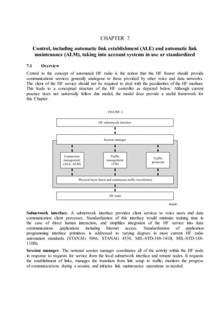
  • 1. CHAPTER 7 Control, including automatic link establishment (ALE) and automatic link maintenance (ALM), taking into account systems in use or standardized 7.1 Overview Central to the concept of automated HF radio is the notion that the HF bearer should provide communications services generally analogous to those provided by other voice and data networks. The client of the HF service should not be required to deal with the peculiarities of the HF medium. This leads to a conceptual structure of the HF controller as depicted below. Although current practice does not universally follow this model, the model does provide a useful framework for this Chapter. Subnetwork interface. A subnetwork interface provides client services to voice users and data communication client processes. Standardization of this interface would minimize training time in the case of direct human interaction, and simplifies integration of the HF service into data communications applications including Internet access. Standardization of application programming interface primitives is addressed to varying degrees in most current HF radio automation standards (STANAG 5066, STANAG 4538, MIL-STD-188-141B, MIL-STD-188- 110B). Session manager. The notional session manager coordinates all of the activity within the HF node in response to requests for service from the local subnetwork interface and remote nodes. It requests the establishment of links, manages the transition from link setup to traffic, monitors the progress of communications during a session, and initiates link maintenance operations as needed. Freq-02 HF subnetwork interface Session manager Traffic management (TM) Connection management (ALE, ALM) Traffic protocols Physical layer (burst and continuous traffic waveforms) HF radio FIGURE 2
  • 2. Connection manager. A connection manager is specifically concerned with establishing and maintaining links of specified characteristics (e.g., SNR). It executes ALE and ALM protocols upon request of the Session Manager, or autonomously when it detects a need for such action. Traffic manager. A traffic manager employs a traffic setup protocol to negotiate the waveforms, protocols, and related aspects of a traffic session. 7.2 ALE As noted in Chapter 1, the first generation of ALE systems was developed in the late 1970s and early 1980s. These groundbreaking systems from numerous manufacturers collectively introduced most of the techniques now in use worldwide. However, no single system included all of the attractive features, and the various proprietary systems were not interoperable. A cooperative effort among the manufacturers and the U.S. government led to a second-generation ALE system that incorporated features from many of the first-generation systems, and also increased linking performance. The second-generation (2G) ALE system was standardized in 1986 in MIL-STD-188-141A, Appendix A, for military use, and later in US FED-STD-1045 for all U.S. government agencies. This 2G ALE technology has become the de facto standard for ALE worldwide. In the late 1990s, parallel efforts led to the development of a third-generation ALE system with higher-performance that retains interoperability with 2G ALE. This 3G ALE has been standardized in MIL-STD-188-141B Appendix C, and as the automated radio control system (ARCS) in STANAG 4538. Both 3G ALE standards mandate interoperability with 2G ALE, which remains in Appendix A of MIL-STD-188-141B. The essence of ALE is automatic channel selection (ACS), scanning receivers, and a selective calling handshake employing robust burst modems that rapidly establishes communications between the calling and called stations. Automatic channel selection (ACS). ALE dynamically selects a frequency for each session from a pool of assigned frequencies. This ACS function uses some combination of propagation predictions, measurements made using the ALE and other waveforms, and propagation reports provided by external systems to select a frequency that satisfies some criterion such as best estimated SNR, or minimum calling time that will satisfy a minimum acceptable SNR. Initial channel selection is made by the station that initiates a link. In some cases (e.g., point-to- point calls using 3G ALE), the called station can override this selection to select a better channel for traffic. Scanning receivers. ALE receivers scan through the assigned pool of frequencies, listening for calls. When receivers are scanning synchronously, according to a deterministic schedule, a short call suffices to reach a receiver. However, synchronous scanning requires network synchronization which may not be practical in all networks. Allowing network stations to scan independently, i.e., asynchronously, reduces the overhead required to synchronize the stations, but introduces the need for an extended call to capture unsynchronized receivers.
  • 3. The scanning rate is bounded by the time required to detect ALE signalling (50-100 ms). Also, high scanning rates have been found to increase failure rates in antenna couplers when the coupler is retuned for each receive frequency. Current dwell times range from 100 ms in fast 2G systems to 5400 ms in ARCS; despite the comparatively leisurely scanning rate of synchronous-mode 3G ALE, its synchronous operation usually results in faster link establishment than is achieved by 2G ALE. Selective calling. ALE stations are assigned addresses (call signs) that are sent in ALE calls using a robust modem. The use of addresses in calls provides both a positive squelch that is effective in HF channel conditions, and a mechanism to minimize interference to stations not addressed. ALE stations recognize both individual addresses and collective addresses. The latter are used to contact multiple stations using a single call. Link establishment handshake. The function of the ALE handshake is to manage the transition from radios that are scanning, available for calls, to radios that are positively linked on a usable channel for traffic. The initial contact is attempted by the calling station. A response from the called station(s) confirms to the calling station that the call has succeeded, but an acknowledging third transmission from the calling station to the called station(s) is needed to positively establish that the link is operational. 7.2.1 ALE modems The requirements for an ALE modem differ significantly from those for a traffic modem. The ALE handshake consists of short transmissions. This makes long synchronization preambles unattractive, and precludes the use of long interleavers in coping with channel error bursts. Different approaches to meeting these requirements have been followed in the early and more recent generations of ALE technology. The first and second generations were developed in the 1970s and 1980s when the cost and power requirements of signal processing hardware mandated simple waveforms. The third-generation ALE waveform links at 7-10 dB lower SNR than the second-generation waveform by taking advantage of 1990s digital signal processing technology. 7.2.1.1 FSK ALE modem (second generation) The second-generation (2G) ALE waveform is an 8-ary frequency shift keying (FSK) modulation with eight orthogonal tones. Each tone is 8 ms in duration and ranges in frequency from 750 Hz to 2500 Hz with 250 Hz separation between adjacent tones. Each tone represents three bits of data, resulting in an over-the-air data rate of 375 bits/s. Forward error correction (FEC) is applied to protocol data bits sent using this waveform. First, the extended (24,12) Golay code is applied, followed by interleaving and triple redundancy. The receiver employs majority voting among the triply redundant symbols received to correct some errors. After deinterleaving the majority symbols, the Golay decoder attempts to recover error-free ALE words. The format of 2G ALE words, shown below, includes a 3-bit preamble and 21 data bits (which are often used to convey three 7-bit ASCII characters). The on-air duration of each 2G ALE word is 392 ms. The function of each transmitted ALE word is designated by the preamble code. There are
  • 4. eight word types: TO, THIS IS, THIS WAS, DATA, REPEAT, THRU, COMMAND, and FROM. The uses of these ALE words are described later. Because no bits in the ALE word are spent on synchronization, acquiring word synchronization in this system employs a series of tests after each received symbol (tri-bit) is shifted in. First, the number of unanimous votes in the majority voter must exceed a threshold. Next, the Golay decoder must successfully decode both halves of the 48-bit majority word. Finally, the resulting 24-bit ALE word must contain a valid preamble and data bits (i.e., must be acceptable to the ALE protocol module). Once word synchronization has been achieved, it is automatically tracked for the remainder of the transmission using the same series of tests. 7.2.1.2 Burst PSK ALE modem (third generation) The 3G ALE waveform is a member of a high-performance family of burst waveforms (BW) that cover the entire range of applications from link setup to traffic and link maintenance. All of the burst waveforms use an 8-ary PSK serial tone modulation of an 1 800 Hz carrier at 2400 symbols/s. The BW0 burst used for 3G ALE carries a 26-bit payload at an effective code rate of 1/96 with a total duration (including sync preamble) of 613 ms. Other members of the BWn family are used for traffic management and link maintenance (BW1) and for ARQ (BW1 through 4). 7.2.1.3 Performance of ALE modems Measurement of linking probability of the second- and third-generation ALE systems indicates the performance of their associated modems. Results for an additive white Gaussian noise (AWGN) channel, as well as ITU-R Good and Poor channels, are plotted in Fig. 3. Freq-02b 3 21 Preamble Data field Freq-03 –15 –10 –5 0 5 10 0 1 3G AWGN 3G Poor 3G Good 2G AWGN 2G Poor 2G Good 0.1 0.2 0.3 0.4 0.5 0.6 0.7 0.8 0.9 SNR Probability of link set up FIGURE 3
  • 5. 7.2.2 ALE protocols The two current generations of ALE protocols were designed to meet differing needs. The 2G ALE system grew out of the need for an interoperable system with great flexibility that would ease the reconstitution of communications after natural or other unforeseen disruptions. It operates asynchronously so that no global timing reference is required. The 3G ALE system was developed to extend the 2G system in two directions: operation in more challenging environments (e.g., lower SNR), and more efficient operation to support large networks and data-intensive applications. Both generations require that operating variables in network member stations (e.g., channels and addresses) have at least some values in common. This may be accomplished manually (using fill devices for example) or through a network management protocol. 7.2.2.1 Second-generation ALE Basic link establishment is accomplished in the 2G ALE system via a 3-way handshake between the linking parties. In the simplest case, the calling station transmits the address of the called station in a 2G ALE word with a “TO” preamble, repeats the TO word, and concludes with its own address in a THIS IS word. This three word transmission is the call phase of the handshake. The repeated address of the destination of a call is common to all 2G ALE transmissions in any handshaking protocol, and is termed the leading call portion of the transmission. It lasts at least two ALE words, or 784 ms. The called station may return a response, which begins with a leading call addressing the calling station, and concludes with its own address in a THIS IS word. Upon receipt of the response, the calling station is assured of bilateral connectivity; it completes the 3-way handshake by sending an acknowledgment to the called station, so that it too is informed that both directions of the link are functional. In this simple case of link establishment, each transmission in the handshake contains only three ALE words, and lasts 1.2 s. Addressing modes. Variations on this linking protocol include using longer addresses (up to 5 ALE words or 15 characters), addressing a network by name in the leading call, in which case the network members respond in prearranged time slots; listing a group of addressees, with response slots in the reverse of the order listed; and scanning variants of these individual, net, and group calls. The characters in 2G ALE addresses are constrained to come from a 38-character subset of the 7-bit ASCII set: A-Z, 0-9, @, and ?. Scanning calls. When the station(s) to be called are scanning through a sequence of channels, the call (only) as described above is modified by prepending enough repetitions of the unique first address word(s) of the addressees that all scanning stations will land on the channel carrying the call at least once during this scanning call portion of the call. The duration of this period is computed from the scanning dwell time and number of channels scanned, and is abbreviated Tsc.
  • 6. Link termination. Links are actively terminated using transmissions ending in THIS WAS (versus THIS IS), and may also be passively terminated upon the expiration of a wait-for-activity timer in the ALE protocol module. Upon link termination, stations that are programmed to scan resume scanning. Orderwire commands. Additional protocols are defined for link management functions and packet data exchange which employ message sections embedded within ALE transmissions (i.e., between the leading call and the THIS IS or THIS WAS termination). These orderwire messages begin with an ALE word with a command message display (CMD) preamble. The remaining bits of the ALE word specify one of several control or data transfer functions. A few of the more popular are listed below: – The automatic message display (AMD) command is mandatory in the 2G ALE standards, and provides a non-ARQ messaging capability that uses the 2G ALE waveform to convey short messages (up to 90 characters). – The link quality analysis (LQA) command, also mandatory, is used to report measured link quality among ALE controllers so that both ends of a link are aware of the bidirectional propagation characteristics. – Data test message (DTM) and data block message (DBM) are optional message transfer modes that provide ARQ using the ALE modem. Quick call ALE A recent development in 2G ALE, called alternative quick call ALE, retains much of the flexibility of the original 2G ALE while improving calling latency. Addresses are always 6 characters in length, and are sent in compressed form in two ALE words. The bits made available by this compression are used to embed selected orderwire functions into the handshake. 7.2.2.2 Third-generation ALE Third-generation ALE (3G-ALE) is designed to establish quickly and efficiently one-to-one and one-to-many (both broadcast and multicast) links. It supports trunked-mode operation (separate calling and traffic channels) as well as sharing any subset of the frequency pool between calling and traffic. It uses a specialized carrier-sense-multiple-access (CSMA) scheme for calling channel access control, and regularly monitors traffic channels to avoid interference. Scanning. As in second-generation ALE, 3G-ALE receivers scan an assigned list of calling channels, listening for 2G or 3G calls. However, 2G-ALE is an asynchronous system in the sense that a calling station makes no assumption about when a destination station will be listening to any particular channel. 3G-ALE includes a similar asynchronous mode, but it achieves its highest performance under synchronous operation. When operating in synchronous mode, all scanning receivers in a 3G-ALE network change frequency at the same time (to within a relatively small timing uncertainty). It is not necessary that all stations monitor the same calling channel at the same time, however. By assigning groups of
  • 7. network members to monitor different channels in each scanning dwell, calls directed to network member stations will be distributed in time and/or frequency, which greatly reduces the probability of collisions among 3G-ALE calls. This is especially important under high-traffic conditions. The set of stations that monitor the same channels at the same time is called a dwell group. Calling channel management. Assignment of channels to 3G-ALE scan lists may be static, but may also be managed dynamically via the network management protocol (HNMP or SNMP). This provides a direct means for propagation prediction programs or external sounders to optimize scan lists “on the fly”. Channels will usually be assigned to scanning sequence in non-monotonic frequency order. By alternating among frequency bands in adjacent dwells (to the extent feasible for the receiving equipment) we increase the probability of linking success in the second dwell when the first frequency tried did not propagate, and so on. Addressing. One of the functions of the subnetwork layer is translation of upper-layer addresses (e.g., IP addresses) into whatever peculiar addressing scheme the local subnet uses. The addresses used in 3G-ALE protocol data units (PDUs) are 11-bit binary numbers. In a network operating in synchronous mode, these addresses are partitioned into a 5-bit dwell group number and a 6-bit member number within that dwell group. Up to 32 dwell groups of up to 60 members each are supported (1920 stations per net). Four additional unassignable addresses in each group (1111xx) are available for temporary use by stations calling into the network. When it is desired to be able to reach all network members with a single call, and traffic on the network is expected to be light, up to 60 network member stations may be assigned to the same dwell group. However, this arrangement does not take full advantage of the 3G calling channel congestion avoidance techniques. To support heavier call volume than the single group scheme will support, the network members should be distributed into multiple dwell groups. This results in spreading simultaneous calls more evenly over the available frequencies. Synchronous dwell structure. The nominal duration of each synchronous dwell is 5.4 s. The timing structure within each synchronous dwell time is as follows (see Fig. 4). Freq-04 Slot 0 Slot 1 Slot 2 Slot 3 Slot 4 Slot 5 Used only for monitoring a traffic channel Used only for calls Used for calls and responses Used for responses and notifications FIGURE 4
  • 8. Tune time. A buffer period, generically denoted “tune time”, is placed at the beginning of each dwell period. During this time, synthesizers are retuned to the new receiving frequency, couplers are tuned as necessary, and so on. Listen time. Following the buffer period, every receiver samples a traffic frequency in the vicinity of the new calling channel, attempting to detect traffic. This “listen time” occupies the remainder of Slot 0, which has a duration of 900 ms. It immediately follows the buffer period because the radio will then be tuned to a nearby frequency, and precedes the calling slots so that stations have recent traffic channel status for use during a handshake. Calling slots. The remainder of the dwell time is divided into 5 equal-length slots. These slots are used for the synchronous exchange of PDUs on calling channels. 900 ms per slot allows for a 613 ms PDU (including 106.7 ms for AGC settling), 87 ms of propagation, and 200 ms for synchronization uncertainty of 100 ms. Synchronous calling overview. The 3G-ALE synchronous calling protocol seeks to find suitable channel(s) for traffic and transition to them as quickly as possible. This minimizes occupancy of the calling channels, which is important in any CSMA system. 3G-ALE calls indicate the type of traffic to be carried (in general terms); the first traffic channel(s) that will support this grade of service will be used. The system normally does not spend time seeking the best channels for traffic. When a calling station is directed to establish a link to a prospective responding station, the calling station will compute the frequency to be scanned by the responding station during the next dwell and randomly (though not uniformly) select a calling slot within that dwell time. During the listen time of that dwell, the calling station listens to a nearby traffic channel that has recently been free of traffic to evaluate its current occupancy. (A station with multiple receivers listens to multiple traffic channels during the listen time.) If not calling in Slot 1, the calling station listens on the calling channel for other calls during the slots that precede its call. If it detects a handshake, it will defer its call. If no other handshake is detected that will extend into its chosen slot, the calling station sends a Call PDU (described later) in that slot and listens for a response in the next slot. When a station receives a Call PDU addressed to it, it responds in the next slot with a Handshake PDU. The Handshake PDU may designate a good traffic channel for transmissions to that responding station. If it does, the calling station will tune to that traffic channel and send a Handshake PDU that either confirms the usability of that traffic channel(s) or designates an alternate traffic channel. When the stations have agreed on a simplex or duplex traffic link, the calling station commences the traffic described in the call. If the call does not result in a link, the caller will proceed to the next calling channel in the responding station’s scan list during the next dwell. The calling station will again select a slot and start the handshake in this new dwell by sending a Call PDU. If the calling station does not succeed in establishing a link after calling on all calling channels, it will normally abort the linking attempt to avoid further channel occupancy.
  • 9. Listen-before-transmit. Every calling station that will send a PDU during a dwell must listen on its intended calling channel during the slots that precede its transmission (except Slot 1). If it detects a handshake, it will defer its call until an available slot or until the next dwell. Thus, early slots in a dwell may preempt later slots. Prioritized slot selection. The probability of selecting a slot is randomized over all usable slots, but the slot selection probabilities for higher-priority calls are skewed toward the early slots while low-priority calls are skewed toward the later slots. Such a scheme will operate reasonably well in all situations, whereas a hard partitioning of early slots for high and late slots for low priorities would exhibit inordinate congestion in crisis and/or routine times. Any number of priority levels can be accommodated in this way. An example set of probabilities is shown below: Third-generation ALE PDUs The PDUs used in one-to-one calling are the Call and Handshake PDUs, as noted above. These two key PDUs are discussed below. Other PDUs are discussed later, with their respective protocols. Call PDU The Call PDU needs to convey sufficient information to the responder so that that station will know whether it wants to respond, and what to listen for during the traffic channel check. The Call PDU must therefore report: – the calling station identification; – the priority of the incoming call; – what resources will be needed if the call is accepted; – what traffic channel quality is required. The Call Type field in the Call PDU specifies the type of traffic and whether the calling station or the called station will send the second (Handshake) PDU. The full called station address is not needed in the Call PDU, because the called station group number is implicit in the choice of the channel that carries the call. Handshake PDU The Handshake PDU is used by both calling and responding stations. It is sent only after a Call PDU has established the identities of both stations in one-to-one link establishment, as well as the Probability of Calling in Slot Traffic Priority 1 2 3 4 Highest 50% 30% 15% 5% High 30% 45% 15% 10% Routine 10% 15% 45% 30% Low 5% 15% 30% 50%
  • 10. key characteristics of the traffic that will use the link. The commands carried in Handshake PDUs include: – “Continue Handshake” (link establishment is deferred until a suitable channel is found); – “Commence Traffic Setup” (link establishment is complete, and data traffic will now be set up); – “Voice Traffic” (link establishment is complete, and voice traffic will now begin). Point-to-point link establishment The point-to-point linking protocol establishes communications on a frequency or pair of frequencies relatively quickly (i.e., within a few seconds), and minimizes channel occupancy during this link establishment process. It will conclude the link establishment process as soon as suitable frequencies have been identified, and does not attempt to find the best available frequencies. A station will normally commence the link establishment protocol immediately upon receiving a request to establish a link with another station, although it may defer the start of calling until the called station will be listening on a channel believed to be propagating. The latter option serves to reduce channel occupancy, and does not preclude calling on the bypassed channels later if the link cannot be established on the favoured channel. A 3G ALE call is illustrated in Fig. 5. The first call occurs in Slot 3. The responder receives the call, but has not identified a traffic channel suitable for the requested traffic, and therefore sends a Handshake PDU containing a Continue Handshake command. In the next dwell, both stations tune during Slot 0, then listen for occupancy on a nearby traffic frequency. The caller selects Slot 1 this time, and the responder has determined that an associated traffic channel was available. When the Call PDU is received by the responder, the measured channel quality is sufficient for the offered traffic, and the responder sends an Handshake PDU containing a Commence Traffic Setup command that indicates the traffic channel to be used. Both stations tune to that channel in the following slot (denoted by cross-hatched areas), and the caller initiates the traffic setup protocol. Freq-05 Caller Responder Continue Dwell frame Frequency 1 Frequency 2 Traffic frequency Caller Responder Caller Responder (Listen) (Listen) Call Commence Traffic requested Call Slot 3 Slot 4 Slot 5 Slot 0 Slot 1 Slot 2 Slot 3 Slot 4 FIGURE 5 Traffic confirmed
  • 11. One-to-many calling One-to-many calling (point-to-multipoint) includes both broadcast and multicast protocols. Broadcast calls are intended for all stations in a network that receive the call, while multicasts are intended only for pre-arranged subsets of the network members. Multicast calls. A multicast call is sent using the Call PDU, as in point-to-point calling, but the call type is set to Multicast Circuit. The Handshake PDU is sent by the calling station, and will normally contain a Commence Traffic command and the channel to be used for traffic . Broadcast calls. A Broadcast PDU directs every station that receives it to a particular traffic channel, where another protocol (possibly voice) will be used. A station may send a Broadcast PDU in every slot in a dwell (except slot 0), and it can change channels every slot to reach a new dwell group. The calling station need not check occupancy on each new calling channel before transmitting. The Broadcast PDU contains a countdown field. At the beginning of slot 1 in the dwell after the caller sent Broadcast PDU(s) with the countdown field set to 0, the caller commences voice traffic or data traffic setup on the indicated channel. Stations that receive a Broadcast PDU and tune to the indicated traffic channel return to scan if traffic setup does not begin within the traffic wait timeout period after the announced starting time of the broadcast. Operators can disable execution of the broadcast protocol. Notifications. The Notification PDU carries the complete address of the sending station. The 3-bit Station Status field carries the current sending station status. This PDU is used as follows: When stations track the departures of other stations to traffic channels, a station that completes a traffic phase and returns to scan should send a Nominal status notification on one or more channels that are believed to propagate to other network members. Stations that are commencing radio silence (or EMCON), or that are voluntarily departing from the network, may notify other stations of this status change to reduce the effects of upper-layer routing protocols having to discover this change in status. Notification PDUs are sent the final slot of a dwell. Sounding. Sounding will normally be unnecessary in 3G-ALE systems. Knowledge of propagating channels can be used, as described earlier, to delay the start of calling and thereby reduce calling channel occupancy. However, with synchronous scanning, knowledge of propagating channels will have only slight effect on linking latency unless non-propagating channels are removed from the scan list (see calling channel management, above). In asynchronous 3G-ALE networks, sounding may be desired if propagation data is unobtainable by other means. In this case, periodic trans- missions of a repeated Notification PDU indicating Nominal station status will serve the purpose.
  • 12. Asynchronous operation. A special Scanning Call PDU is sent repeatedly to capture scanning receivers when a network is operating in asynchronous mode. As in the 2G system, the scanning call carries just the called station address. The identity of the calling station is unknown until the end of the call, which will be the normal Call PDU in this case. 7.3 ALM After ALE has completed its work, a traffic setup protocol is normally employed to manage the transition to traffic on a link. This may include routing audio to specific channels at each station, setting initial modem rates and modulations, establishing data routing within the station, and so on. When data traffic is passed over the link, an ARQ protocol is usually employed to correct errors. The ARQ protocol is thus acutely aware of degradation of channel conditions that may mandate a change in frequency. In the case of analog voice operation, the operators may be relied upon to request link maintenance when the channel becomes unacceptable. Modem and data link characteristics are normally managed by the ARQ protocol. Power control is usually either absent in a system, or is managed by a dedicated process. This leaves changing the traffic frequency as the principal tool for an ALM mechanism. 7.3.1 ALM protocol requirements An ALM action request requires the that following functions be satisfied: – a suitable alternate frequency be discovered; – an unambiguous means is provided to coordinate both nodes changing to the new frequency: – interference to other nodes is minimized. 7.3.2 ALM protocol The ALM protocol in ARCS (3G ALE) is used by the connection management (CM) process to maintain links established using 3G ALE. All stations support the mandatory function: – forced return to link setup using the LM_Relink PDU. The following optional functions are also defined for ARCS: – coordinated departure to suitable alternate frequencies as required by changing propagation and interference conditions (logical link is not dropped); – probing of candidate alternative frequencies during traffic; – negotiation of frequencies for operating modes other than simplex (i.e., half- or full- duplex); – renegotiation of waveform, data rate, and interleaver. The protocol employs the robust BW1 waveform to convey its 48-bit PDUs. A Countdown field in the LM PDUs contains the number of times the PDU will be resent before the indicated change is to take effect. The sequence of LM PDUs is sent contiguously, ending with the PDU that contains a Countdown value of 0. The number of repetitions of the LM PDU is chosen to reduce to an acceptable level the probability that it will be missed by the other station(s).
  • 13. Relink. Either station in a point-to-multipoint link, or the calling station in a point-to-multipoint link, may initiate a return to link setup by sending LM_Relink PDU(s). All stations in the logical link will immediately return to scan. The station that originally set up the logical link should initiate ALE to re-establish it. No response is made to this PDU; it is simply passed to the Connection Manager process at each receiving station. Duplex link negotiation. At any time after a link is established on a traffic channel, including the time usually used for traffic setup, a station may send a sequence of LM_Duplex PDUs that indicates a channel on which other station(s) are requested to send future transmissions to the requesting station. All of the LM_Duplex PDUs are identical except for the Countdown field. The sending station will continue to transmit on its current traffic channel after the change. Coordinated departure to new traffic channels. Coordinated departure to new traffic channel(s) employs the LM_Simplex and/or LM_Duplex PDUs as appropriate, to indicate a new frequency on which it will listen for traffic. – LM_Duplex PDU(s) indicate that the sending station will continue to send on its current transmit frequency until another frequency is negotiated. – LM_Simplex PDU(s) indicate that the sending station will change its transmit frequency as well as its receive frequency to that indicated in the LM_Simplex PDU. If the sending station detects protocol failure via timeout, or other means, after changing its receive frequency, it will execute the Relink protocol, drop its logical link, and recommence link setup. Negotiation of waveform. A Waveform Change PDU is used to negotiate waveform(s) to be employed on a logical link, using waveform codes identical to those used in traffic setup.