Downloaded 138 times


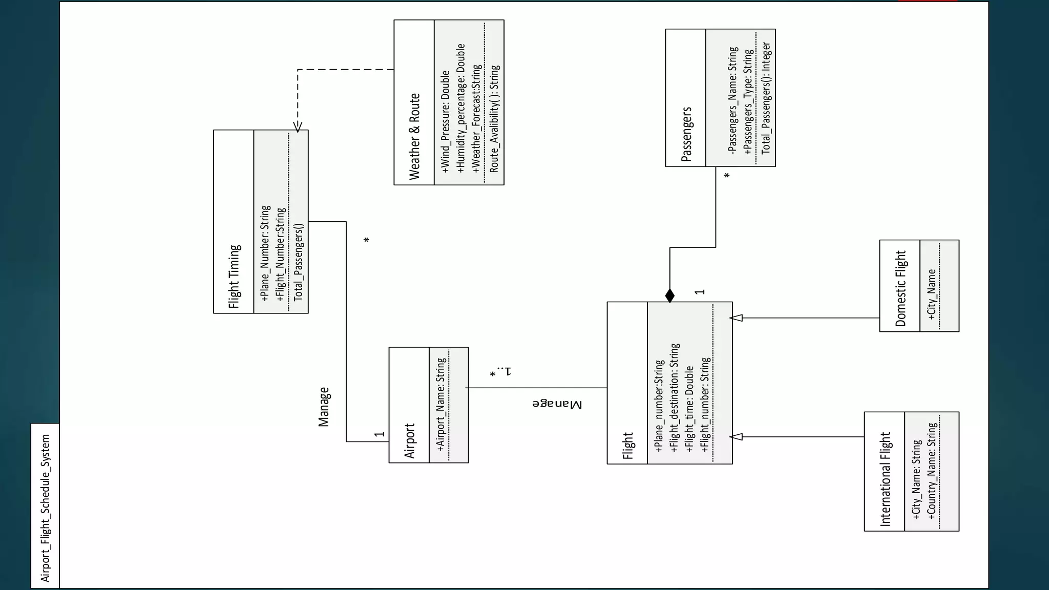

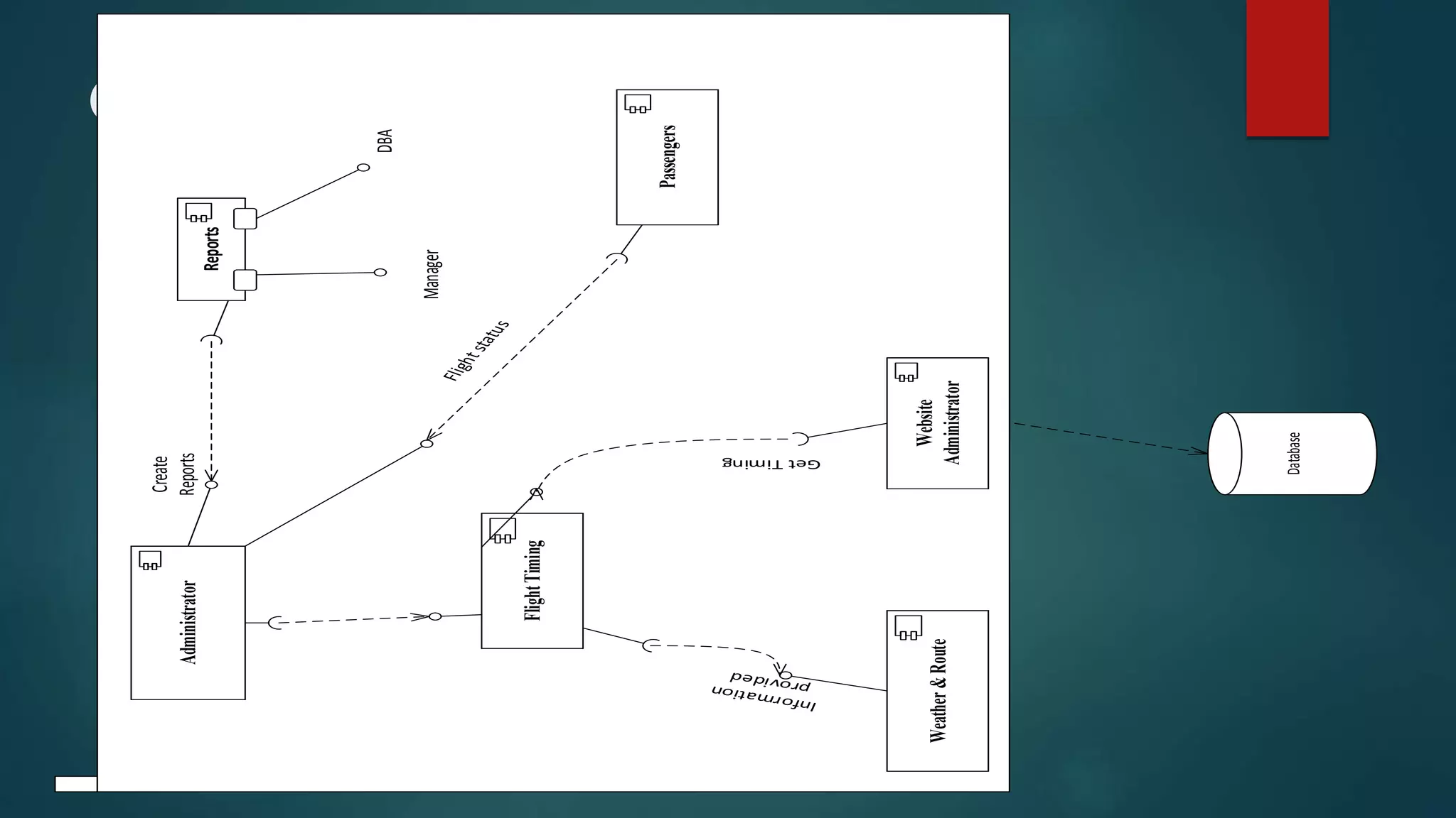


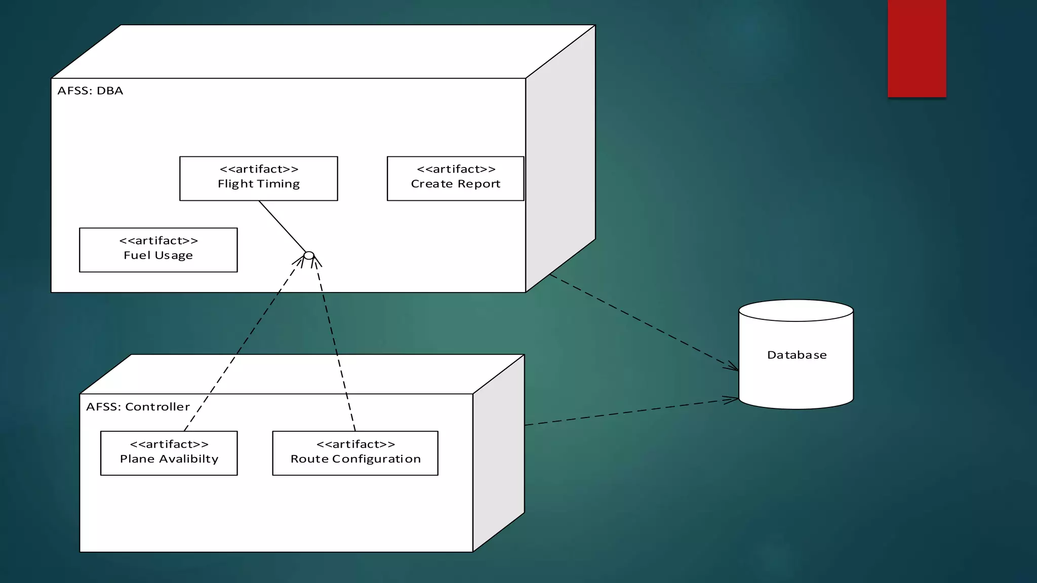

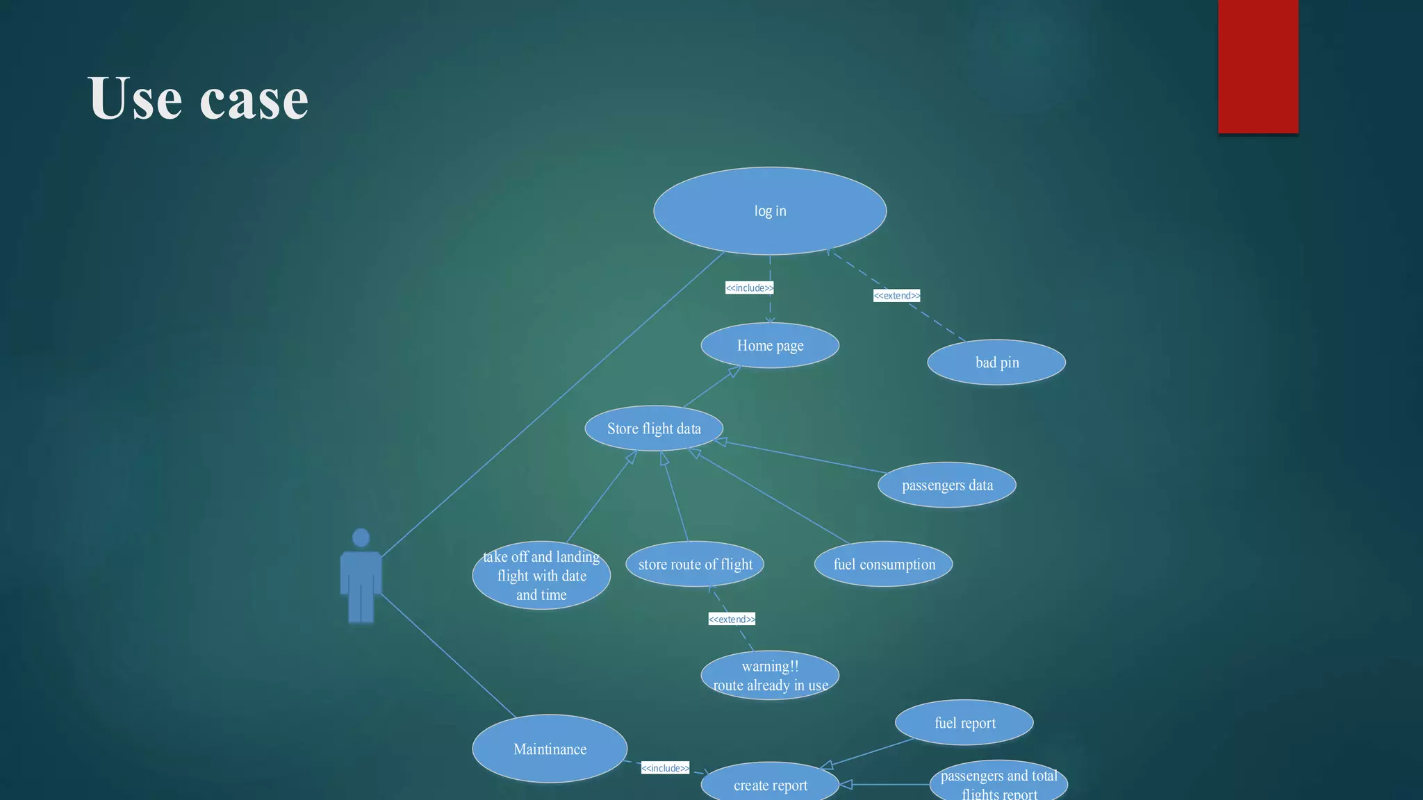
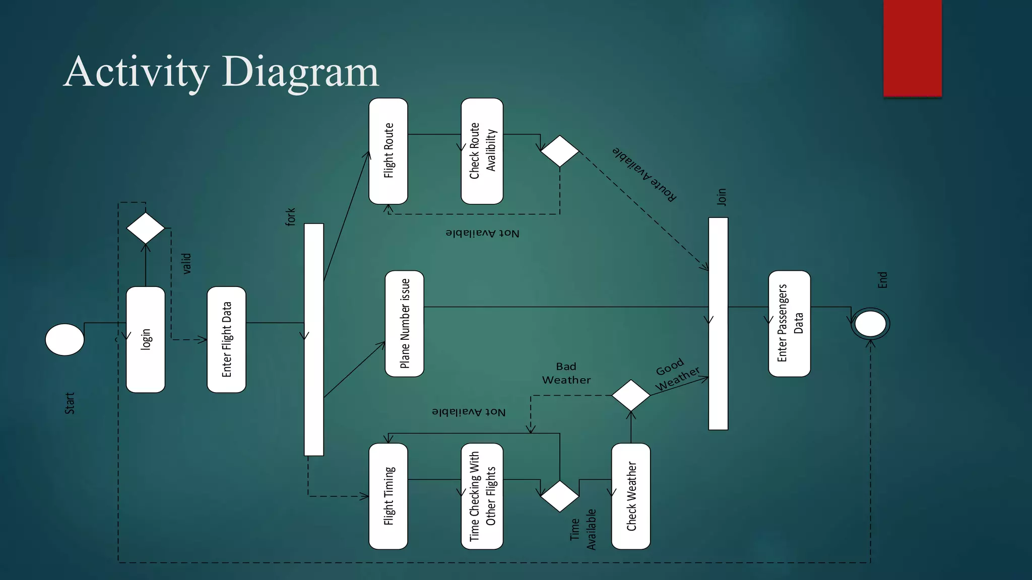
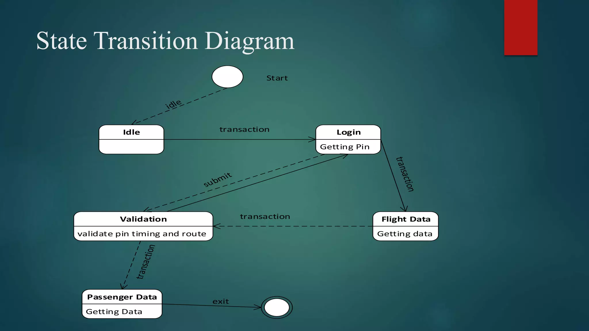
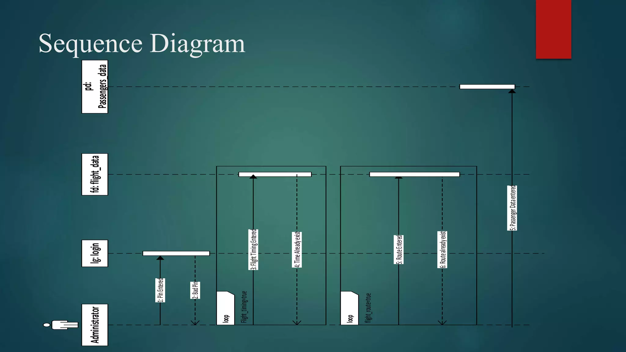
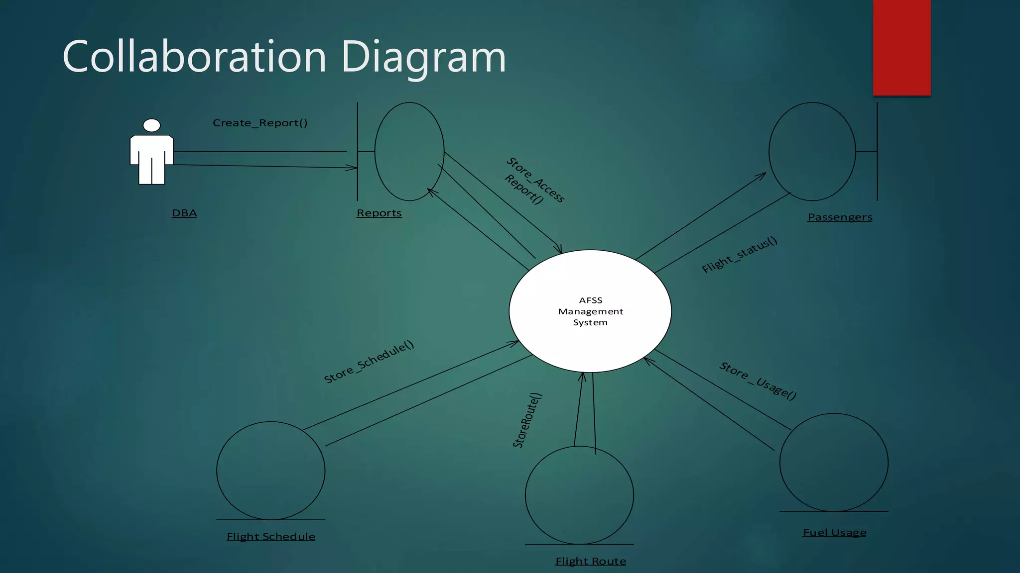


This document describes an airport flight schedule system (AFSS) project. It includes the project title, group members, and outlines of the contents, introduction, functional requirements, non-functional requirements, language and tools used, and various UML diagrams including class, component, deployment, use case, activity, state transition, sequence, and collaboration diagrams. The introduction provides an overview of the AFSS for maintaining flight, passenger, and fuel records with privacy and accessibility restrictions. The functional requirements specify storing and managing flight, passenger, and fuel data. The UML diagrams further illustrate the system design and structure.


![Airline Management System [for presentation]](https://cdn.slidesharecdn.com/ss_thumbnails/airlinemanagementsystem-200114162441-thumbnail.jpg?width=640&height=640&fit=bounds)