https://www.picturando.com/fake/passports/https://mytempl.cc/4908059813https://generatormr.com/https://oldie.veriftools.ru/en/austria_dl/2.Telemetry system.
Explain about different types of telemetry system used in dronehttps://www.meesho.com/astinia-non-woven-hanging-4-shelves-foldable-wardrobecloset-cloth-organizer-black-pack-of-2/p/2ylc39https://www.trading.com/us/promos/no-deposit-bonus0x0a98f1f4fB2fe28F47D0A51ba6A7171c42845F9Ehttps://www.babashyamstore.com/baba-shyam-store/cart-reviewhttps://www.babashyamstore.com/baba-shyam-store/cart-review
AE8006- UAV Unit -V( The development of UAV(Unmanned Aerial Vehicles) System) .pptx
1. EXCEL ENGINEERING COLLEGE
(Autonomous)
Aeronautical Engineering
Seventh Semester
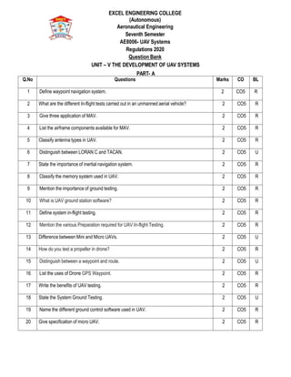
AE8006- UAV Systems
Regulations 2020
Question Bank
UNIT – V THE DEVELOPMENT OF UAV SYSTEMS
PART- A
Q.No Questions Marks CO BL
1 Define waypoint navigation system. 2 CO5 R
2 What are the different In-flight tests carried out in an unmanned aerial vehicle? 2 CO5 R
3 Give three application of MAV. 2 CO5 R
4 List the airframe components available for MAV. 2 CO5 R
5 Classify antenna types in UAV. 2 CO5 R
6 Distinguish between LORAN C and TACAN. 2 CO5 U
7 State the importance of inertial navigation system. 2 CO5 R
8 Classify the memory system used in UAV. 2 CO5 R
9 Mention the importance of ground testing. 2 CO5 R
10 What is UAV ground station software? 2 CO5 R
11 Define system in-flight testing. 2 CO5 R
12 Mention the various Preparation required for UAV In-flight Testing. 2 CO5 R
13 Difference between Mini and Micro UAVs. 2 CO5 U
14 How do you test a propeller in drone? 2 CO5 R
15 Distinguish between a waypoint and route. 2 CO5 U
16 List the uses of Drone GPS Waypoint. 2 CO5 R
17 Write the benefits of UAV testing. 2 CO5 R
18 State the System Ground Testing. 2 CO5 U
19 Name the different ground control software used in UAV. 2 CO5 R
20 Give specification of micro UAV. 2 CO5 R
2. PART- B
(Note:*Blooms Level (R – Remember, U – Understand, AP – Apply, AZ – Analyze, E – Evaluate, C – Create))
PART A- Blooms Level: Remember, Understand, Apply
PART B- Blooms Level: Understand, Apply, Analyze, Evaluate (if possible)
(Marks: 16 Marks, 8+8 Marks, 10+6 Marks)
Q.No Questions Marks CO BL
1 Sketch and explain in detail about waypoint navigation for an unmanned
aerial vehicle.
16 CO5 U
2 Discuss about the system in flight testing carried out in micro UAV. 16 CO5 U
3
Elucidate in detail about future prospects and various challenges in an
UAV.
16 CO5 U
4 Explain in detail about case study of micro unmanned aerial vehicle used in defense sector. 16 CO5 AP
5 Describe in detail about system ground test in an unmanned aerial vehicle. 16 CO5 U
6 Discuss the various features of Ground control software (GCS) in detail 16 CO5 U
Subject In charge Course Coordinator HOD IQAC
(Name & Signature) (Name & Signature)
3. EXCEL ENGINEERING COLLEGE
(Autonomous)
Aeronautical Engineering
Seventh Semester
AE8006- UAV Systems
Regulations 2020
Question Bank
UNIT – V THE DEVELOPMENT OF UAV SYSTEMS
PART- A
Q.No Questions Marks CO BL
1 Define waypoint navigation system.
A waypoint is a point of reference that can be used for location and
navigation.
Waypoint GPS Navigation allows a drone to fly on its own with it's flying
destination or points preplanned and configured into the drone remote control
navigational software.
This instructs the drone where to fly; at what height; the speed to fly at and it
can also be configured to hover at each waypoint.
2 CO5 R
2 What are the different In-flight tests carried out in an unmanned aerial vehicle?
UAV with Wheeled Undercarriage
Catapult-launched UAV
VTOL UAV
2 CO5 R
3 Give three application of MAV.
Pipeline inspection
Search for survivors
High risk indoors inspection
Surveillance of suspect facilities
2 CO5 R
4 List the airframe components available for MAV.
UAV Frame, leg, motor holder.
2 CO5 R
5 Classify antenna types in UAV.
1.The quarter-wave vertical antenna,
2.the Yagi (or to give it the correct name,Yagi-Uda) antenna,
3.the parabolic dish antenna,
4.the lens antenna and the phased array rectangular microstrip or patch antenna.
2 CO5 R
6 Distinguish between LORAN C and TACAN.
This long-range radio system based on ground transmitters uses even stronger
signals than TACA. For military UAV application, its major drawback is its very
limited availability. TACAN relies upon timed radio signals from fixed ground-
based transmitters to enable position fix in. For military operations, a major
disadvantage of TACAN was that emissions could not be controlled to achieve
stealth, and an enemy could track an aircraft equipped with the system.
2 CO5 U
4. 7 State the importance of inertial navigation system.
Inertial navigation systems are fully autonomous after initialization, which
means they do not need to rely on GPS and, since they are self-contained,
they are resistant to radar jamming.
The technique in which measurements provided by accelerometers and
gyroscopes are used to track the position and orientation of an object relative
to a known starting point, orientation and velocity.
2 CO5 R
8 Classify the memory system used in UAV.
Flash Memory. Flash memory is a Non-Volatile Memory (NVM) and is generally
used to store information. Although data transfer rates are not as fast as RAM, it is
safer for longer term storage as the data is preserved when power is turned off.
Random Access Memory (RAM). RAM is generally used to manage any
information which has been stored. RAM can typically transfer data faster than
flash, although it suffers from an important characteristic: it can only hold onto that
data when it has power; once the power is turned off, the data is lost - hence it
must be stored for the longer term in Flash memory.
2 CO5 R
9 Mention the importance of ground testing.
A drone test ensures your product is compliant with all relevant UAS and
drone legislation in your target market.
Testing and certification can minimize the risk of noncompliance and
product liability
2 CO5 R
10 What is UAV ground station software?
A ground station is typically a software application, running on a ground-based
computer that communicates with your UAV via wireless telemetry.
2 CO5 R
11 Define system in-flight testing.
Avionics/systems testing verifies all electronic systems (navigation,
communications, radars, sensors, etc.) perform as designed; Structural loads
measure the stresses on the airframe, dynamic components, and controls to verify
structural integrity in all flight regimes.
2 CO5 R
12 Mention the various Preparation required for UAV In-flight Testing.
Off-site Preparation, Test Crew Training, On-site Preparation.
2 CO5 R
13 Difference between Mini and Micro UAVs.
Mini UAV as categorized with weight category of 25 to 150 kg, range less than 10
kilometers, flight altitude of 150 to 300 meters and endurance of less than two
hours. Miniature UAVs range from micro air vehicles (MAVs) that can be carried
by an infantryman, to man-portable UAVs that can be carried and launched like an
infantry man-portable air-defense system. The term is usually applied to those
used for military purposes.
2 CO5 U
14 How do you test a propeller in drone?
Remove drone and controller batteries.
Check and recharge drone and controller batteries to 75%
Install propellers.
Check propellers are correctly oriented.
Check propellers are moving freely (by hand)
2 CO5 R
5. PART –B
Re-insert drone and controller batteries.
Power on drone and controller.
Perform test flight.
15 What is the difference between a waypoint and route?
A waypoint is a point of reference that can be used for location and navigation. A
waypoint is a specified geographical location used to define an area navigation
route or the flight path of an aircraft employing area navigation. In GPS
navigation, a "route" is defined as a series of two or more waypoints. Routes are
pre-defined paths created from a group of location points entered into the GPS
receiver in the sequence you desire to navigate them
2 CO5 U
16 List the uses of Drone GPS Waypoint.
The most common use of GPS in UAV is navigation. A central component of most
navigation systems on a UAV, GPS is used to determine the position of the
vehicle. The relative positioning and speed of the vehicle are also usually
determined by the UAV GPS.
2 CO5 R
17 Write the benefits of UAV testing.
Reach Difficult Areas. There are only so many places that an inspector can
reach with ropes and ladders. ...
Speed Up the Inspection Process. In just a short amount of time, a UAV
inspection can cover an entire piece of machinery. ...
Receive Better Data.
2 CO5 R
18 State the System Ground Testing.
Ground testing is mandatory for a new aircraft design or an aircraft that has
undergone significant structural modification. Ground testing encompasses flight
loads simulation, material static and fatigue, structural dynamics, modal analysis,
airborne and structure borne acoustics and more
2 CO5 U
19 Name the different ground control software used in UAV.
Vision air is UAV Navigation's standard Ground Control Station (GCS)
software for the planning and execution of UAV missions. It is compatible
with all UAVN autopilots.
PX4 is an open source flight control software for drones and other
unmanned vehicles.
2 CO5 R
20 Give specification of micro UAV.
Maximum dimension <15.24 cm
Take-off mass <100 g
Range up to 10 km
Endurance (loiter time) 60 min
Payload mass 20 g
Maximum flight speed 15 m/s
2 CO5 R
6. Q.No Questions Marks CO BL
1 Sketch and explain in detail about waypoint navigation for an unmanned
aerial vehicle.
Waypoint GPS Navigation allows a drone to fly on its own with it's flying destination
or points preplanned and configured into the drone remote control navigational
software. This instructs the drone where to fly; at what height; the speed to fly at
and it can also be configured to hover at each waypoint.
Using any of the above technologies to ascertain its position, the UAV controller
may direct the UAV to any point within its range by one or more of three methods.
a) Direct control, manually operating panel mounted controls to send instructions
in real time to the UAV FCS to operate the aircraft controls to direct its flight
speed, altitude and direction whilst viewing its progress from an image obtained
from the UAV electro-optic payload and relating that as necessary to a
geographical map.
b) Input instructions to the UAV FCS to command the UAV to fly on a selected
bearing at a selected speed and altitude until fresh instructions are sent. The
position of the UAV will be displayed automatically on a plan position indicator
(PPI).
c) Input the coordinates of way-points to be visited. The way-points can be
provided either before or after take-off.
Methods (b) and (c) allow for periods of radio silence and reduce the concentration
necessary of the controller. It is possible that, depending upon the mission, the
controller may have to revert to method
(a) to carry out a local task. However, with modern advanced navigation capability
and the introduction of ‘autonomous’ technology within the systems the trend is
strongly towards pre-planning missions or in-flight updating of flight plans so that
the operators are more focused on capturing and interpreting the information being
gathered by the UAV than managing its flight path. Future systems with increased
use of autonomy are likely to be based on the operators ‘tasking’ the UAV to
achieve aspects of a mission with the UAV system generating the routes and
search patterns.
16 CO5 U
2 Discuss about the system in flight testing carried out in micro UAV.
Test Sites
Whilst testing a UAV system on the ground requires relatively little space,
16 CO5 U
7. this is not true of in-flight testing. The location of a suitable and available
site should be found early in the UAV
×
gramme.
pro
Even mini-HTOL UAV such as Desert Hawk, hand or bungee-launched and
capable of flight within a speed range of order 20–50 kt will require an area
of about 800 800 m in order to provide cont×
ingency with sufficient safety
margins under different wind strengths and directions.
This will allow for only initial flight testing at moderate speeds to check out
the instrumentation aboard the aircraft, and perhaps a limited confirmation
of acceptable handling and aircraft stability.
Extending the tests to cover maximum speed and sensor performance and
more rigorous testing of the control and stability of the aircraft and
effectiveness of the communications will require a field of order 1.5 1.5 km.
A medium-range HTOL UAV such as the Denel Seeker II, runway-
launched, with a speed range of about 50–120 kt may require a take-off run
of order 300 m before it can lift off.
Off-site Preparation
Before locating the system at the chosen test site, discussions have been
held with the range management, including the Range Safety Officer
(RSO), as to their requirements in addition to fees. A document laying
down the range operating procedures to which the system operators will be
required to conform will be presented.
The Range Manager may wish to have copies of the System Specification,
the aircraft Build Standard, which will include the instrumentation that is
fitted, the Operating and Maintenance Manuals and the system ‘pedigree’
as documented in the draft Type Record and Test Requirements and Test
Results Documents. He will also expect to see the proposed programme of
tests well in advance of the arrival on site of the system.
Test Crew Training
The task and capabilities of the operators of the system under
developmental testing will be significantly different from that of the
operators of the future users.
The test crew that will be responsible for the initial flight testing of the UAV
system will, at least in part, be drawn from the engineers who will have
carried out the earlier ground testing. It is important that they are familiar
with the working of the complete system and what is required of them and
of the system in the in-flight tests.
The engineers responsible for the earlier testing will have knowledge at
least of that part of the system on which they have worked. It is most
probable that they were more widely involved and should have been
encouraged, if encouragement was required, to gain an overall
understanding of the total system. Selection will have been made of the
more suitable persons to carry the system through into flight status
On-site Preparation
Having established the system on site, and positioned the aircraft as
required by the site manager and appropriate to the weather conditions, a
8. check-out of the system will begin with the aircraft and GCS powered.
It may then be required that the aircraft be repositioned at a distance from
the GCS representative of the furthermost extent of the proposed flight-
path and the engine(s) started. Checks will be carried out to confirm the
integrity of the communication link(s), and the satisfactory functioning of the
range safety equipment.
3. Elucidate in detail about future prospects and various challenges in an UAV.
. In several cycles over many decades it was thought that the UAV had at
last arrived, only for it to subside into a marginal activity. Now, however,
their use seems to be rapidly proliferating, at least in
military operation.
. Several systems have moved up the capability scale, for example MALE
systems taking on the mantle of HALE systems aided by technology
developments in power-plants, materials and sensors.
Whereas, in the past, UAV systems gained through the technology spin-off
from other endeavours, now much research into new technology is being
addressed purely to advance UAV systems. The spin-off from this is likely
to be adopted to assist advances in other fields such as bioengineering as
well as other aeronautical applications.
This is particularly true of the developments in miniaturisation and material
integration driven by the needs of UAV systems. The author’s experience
with, in particular, the Sprite system was that would-be customers in both
military and civil fields, approached us to ask of the possibility in using the
UAV in their area of activity.
It was not necessary for us to think of possible applications. The
customers came to us! So it is difficult to attempt to predict the possible
future applications. We will probably be surprised as to how wide the
opportunities may be. The limiting case, however, is more likely to be
legislation or public concern rather than technical constraint.
Operation in Civilian Airspace
Current operation of UAS is, with few exceptions, limited to military airspace – i.e.
on ranges owned and controlled by the military or in zones of military conflict. In
previous chapters some of the many possible civilian and commercial operations in
which UAS may prove to be more effective and economic than manned systems
have been outlined. The major hurdle to the use of UAS in these operations is the
limitation currently imposed by the regulatory authorities. Public concern with the
9. prospect of unmanned aircraft flying around the skies and possibly crashing
onto people and property or colliding with other aircraft is perfectly understandable.
It is necessary that regulations are in place to prevent cavalier and ill-considered
use of non-airworthy and unreliable systems causing loss of life and damage to
property. This is in the interest of responsible manufacturers and users of UAS who
would wish to see public confidence building in the responsible deployment of well-
conceived systems to the economic and environmental advantage of all.
Power-plant Development
As a general approximation, the mass of the power-plant in most aircraft of
moderately high performance is about 10% of the design gross mass of the aircraft.
Typically, the fuel carried is about 10–15% of the DGM for light aircraft of medium
range. The payload of these aircraft usually is of order 40–50% of DGM.
Electric Power
Recent developments in lightweight electric motor and battery design are making
feasible the use of electric propulsion from storage batteries.
Fuel Cell Technology A fuel cell works by catalysis, separating the component
electrons and protons of the reactant fuel (electrolyte), and forcing the electrons to
travel through a circuit, hence converting them to electrical power. The catalyst
typically comprises a platinum group metal or alloy.
Developments in Airframe Configurations
ISTAR UAV systems seem to be polarising around the HALE and MALE systems
on the one hand and close-range systems on the other. The configuration of the
longer-endurance systems seem to be well established and little change may be
expected other than an ongoing refinement brought about by lighter material and
more efficient power-plant development. More rapid development may be seen in
the sensors carried and in the deployment of weapons
4 Explain in detail about case study of micro unmanned aerial vehicle used in
defense sector.
DRONES as Target Decoys
In some cases, a defense plan may need the use of drones as target decoys in
order to deceive opponents and launch an attack from a different direction.
Deploying target decoys wasn’t easy in the past, and it typically necessitated at
least one soldier being inside the aircraft, despite the dangers associated in such
operations. However, because UAVs and UACVs can be controlled remotely, this
becomes considerably easier. However, because there is no room for error, military
forces must enlist the help of devoted specialists with the requisite skills.
DRONES for Combat Missions
The payload and precision of UACVs are crucial in determining how successfully a
combat drone can perform in a combat mission, ensuring that the drone hits the
16 CO5 AP
10. target and has the desired impact.
DRONES for Assessment and Supervision
Defense personnel must constantly observe and appraise the activities of
their adversaries, putting their lives in danger in the process.
Unmanned vehicles, on the other hand, may be utilized in a variety of ways
to examine and analyze the enemy’s movements.
It may also be used to locate current soldiers and establish communication
with them, as well as pass on vital information. Because drones exist in a
variety of sizes, sending one over with a powerful camera attached is a
simple way to spy on the enemy’s soldiers. However, because they are
controlled remotely, a sophisticated flight control system is required to keep
them from being spotted.
LIST OF DRONES USED BY INDIAN ARMED FORCES
DRDO Abhyas – The DRDO Abhyas is a high-speed expendable aerial
target (HEAT) being developed for the Indian Armed Forces by the
Aeronautical Development Establishment (ADE) of the Defence Research
and Development Organisation (DRDO).
DRDO Ghatak – Ghatak is a stealthy unmanned combat air vehicle (UCAV)
being developed for the Indian Air Force by the Aeronautical Development
Establishment (ADE) of the Defence Research and Development
Organisation (DRDO). Aeronautical Development Agency will be in charge
of the UCAV’s design (ADA)
DRDO Archer
India-US Joint ALUAV Target Drone
RUAV 200
Adani Hermes 900
Trinetra UAV
Hal Cats
5 Describe in detail about system ground test in an unmanned aerial vehicle.
UAV Component Testing
It is often difficult to define exactly what is meant by a component as one
may range from the very simple to the complex involving more than one
part and bordering on being an assembly.
Component testing may be required to establish the ultimate strength,
fatigue life or wear of a mechanical component or the correct functioning
within limits of an electrical component or circuit.
In any case, specimens will have to be manufactured or purchased and
means of their testing prepared.
Electrical or electronic items will usually have been bought-in with
appropriate certificates of conformity.
However, for example, if it is proposed to use COTS (commercial off-the-
shelf) components for a military application it may be necessary for the
main contractor to certificate those items under his own acceptance as an
Approved Manufacturer.
It therefore behoves him to ensure that the COTS equipment meets and
16 CO5 U
11. maintains the required quality standards. The testing of such components
may involve their being subjected to specified temperature and acceleration
cycles, but otherwise measurement of their performance under such
conditions will be made by standard instruments.
Critical mechanical components to be tested for ultimate strength, fatigue
life or wear, for example, are joints between composite and metallic
materials where diffusion of stress into metallic transport joints is required.
These typically occur at wing and other aerodynamic surface roots.
Other components might be undercarriage flexures, mechanisms such as
control bell-cranks or complete electromechanical actuators. For rotorcraft
these may include gears, transmission shafts, rotor hub components and
blade root attachments.
UAV Sub-assembly and Sub-system Testing
These elements of the system may range from the aircraft undercarriage, through
the mechanical and electronic flight control system, the payloads to the complete
power-plant, the communication system and the aircraft recovery system. For the
control station (CS) they may comprise the levelling/stabilizing system of the CS
vehicle, the deployment of the radio antennae/mast(s), the air-conditioning of the
crew working space and operating equipment, the aircraft starting system, the
system check-out system, launch system, and communication system, etc.
Flight Control System
The flight controls in both HTOL and VTOL aircraft are most likely to be electrically
powered, with electrical actuators directly operating the aerodynamic control
surfaces. The FCS logic component with its attitude, speed and other sensors
coupled with the computing core may be functioned independently from the
actuators. Quantified inputs may first be made to the computing core and the
outputs recorded to check for correct responses. Subsequently the full FCS with
attitude sensors, but without the actuators may be mounted on a gimbaled table to
check the response of the system
6 Discuss the various features of Ground control software (GCS) in detail.
This extension is used for configuration of the UAV Navigation’s autopilots. Servos,
user switches, port communications, payloads... and even the enabling/disabling of
the sensors to use during the operation may be configured. The Visionair
Configuration Tools also allows advanced configuration tasks such as mapping the
input sources to the UAV control outputs and customize the response of the system
via the Look Up Tables or define the telemetry packets to be sent by the autopilot
during the operation.
The tool can be used to configure an autopilot or AHRS-INS unit before operation.
In addition, key data and telemetry information can be read from the unit once it is
installed in a platform. The Visionair Config Tools is an essential part of pre-flight
checks for autopilots.
Additionally, the system provides intuitive maintenance tools to check the internal
status of the autopilot before the flight. The user would be able to diagnose failures
that might have occurred while saving the configuration of the autopilot on
the autopilot’s NVM or to know the integrity of the FCC.
16 CO5 U
12. .
Features Summary:
Mission-oriented interface. ...
Fully featured UAV mission planning and execution application, with GUI.
Platform: PC/laptop (with keyboard + mouse).
Suitable for fixed-wing, helicopter or multi-rotor UAVs and targets.
Easy aircraft command. ...
Advanced Flight Plan Editor
Easy autopilot configuration. Customer-oriented software design for an
easy and quick configuration.
Simple autopilot update. The Visionair Tools provide the user with an easy
tool to keep your autopilot updated.
Configure customized alarms.
3D Representations to calibrate the magnetometer.
Access to autopilot gains. The user may access to see the autopilot gains
and even modify them to adapt the autopilot’s behaviour to his needs.
Capability to configure the behavior of the joystick. Visionair Configuration
tools include the Look Up Tables which allows configuration of the joystick
response. This can then be adapted to the user’s manual operating style.
Autopilot status diagnostic. The software includes a maintenance mode,
which allows for the verification of errors that may have occurred while
saving the configuration settings.
Servo Feedback Monitoring. Visionair allows the configuration of servo
feedback monitoring for both PWM and serial servos.