
Recommended
Recommended
More Related Content
What's hot
What's hot (19)
Similar to Advanced Pipeline Risk Assessment vs. Simplified NACE Standards
Similar to Advanced Pipeline Risk Assessment vs. Simplified NACE Standards (20)
More from David Richardson
More from David Richardson (7)
Recently uploaded
Recently uploaded (20)
Advanced Pipeline Risk Assessment vs. Simplified NACE Standards
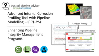
- 1. Advanced Internal Corrosion Profiling Tool with Pipeline Modelling - ICPT-PM Enhancing Pipeline Integrity Management Programs Corrosion Profiling Mitigation Guidance
- 2. Advanced Internal Corrosion Profiling Tool with Pipeline Modelling - ICPT-PM Background Part A
- 3. ICPT-PM Corrosion Modelling Service (1994 – Present) Internal Corrosion Profiling Tool – Pipeline Modelling Q-ICDA ICPT-PM
- 4. How a Simplified Version of ICPT-PM became the Foundation for NACE - ICDA • ICPT-PM is the outcome of a 25-year sustained commitment to rigorous engineering calculations & deep subject-matter knowledge vs. acceptance of simplified flow correlations • In 2001 an INGAA / AGA technical committee embraced ICPT-PM as the foundation of ICDA • INGAA / AGA – ICDA Standard became NACE – ICDA • wet-gas / normally dry-gas
- 5. ICPT-PM is the Foundation of NACE – ICDA Standards for Wet-Gas and Normally Dry Gas Pipelines P i p e F l o Technical Committee – Internal Corrosion 2001 – 2003 (B. Cookingham & O. Moghissi) ICPT-PM Development (1994 – 2003) Calgary, Alberta ICDA Dry Gas / Wet-Gas 2005 PIPESIM / OLGA A simplified method to predict internal corrosion based upon exceedance of critical inclination angle to trigger water hold-up ICPT-PM Consulting Projects Continued David Richardson, P.Eng. 2003 – 2020 ICPT-PM (1994 – Present) ICPT - PM A Sustained Commitment to Rigorous Engineering Models (1994 – Present)
- 6. ICPT-PM Calculations vs. NACE - ICDA • NACE – ICDA is a dramatic simplification of ICPT-PM • ICPT – PM delivers a more accurate corrosion profile than NACE – ICDA simplified flow correlations • NACE – ICDA has a legacy of under-performing for the industry
- 7. Advanced Internal Corrosion Profiling Tool with Pipeline Modelling - ICPT-PM ICPT-PM within ICDA Projects Part B
- 8. smart-Project Management Inc. Internal Corrosion Profiling Tool with Pipeline Modelling (ICPT-PM) 1. ICPT-PM pin-points the most probable locations of corrosion and the severity of corrosion damage • accumulated over-life metal loss along the pipeline; • prioritized regions for integrity validation 2. ICPT-PM provides mitigation guidance for Production Operations • action to prevent corrosion initiation • action plan to prevent growth of pre-existing corrosion damage
- 9. ICPT-PM within ICDA PROJECTS • ICPT-PM corrosion rate & corrosion damage profiles are the foundation of ICDA Projects • ICDA – Step 1 / Pre-Assessment (PrA) • data collection & project execution strategy • ICDA – Step 2 / Indirect Inspection (IDI) • characterization of corrosion rate & corrosion damage profiles / identification of regions of most probable corrosion damage • ICPT-PM provides corrosion mitigation schedules • ICDA – Step 4 / Post Assessment (PoA) & ongoing SMS integrity management process • ICPT-PM characterization of most probable corrosion location profile used to create an integrity validation plan • ICDA – Step 3 / Direct Examination (DEx) • In-line inspection and non-destructive examination of pipe condition at identified integrity dig sites
- 10. ICDA Project Execution - ICPT-PM vs NACE – ICDA Standards ICDA PROJECT Step 1 – ICDA-PrA Step 2 – ICDA-IDI (including ICPT-PM) Step 4 – ICDA-PoA Step 3 – ICDA-DEx ICPT-PM within ICDA Projects Part C
- 11. ICDA Project Workflow ICDA Step 1 – Pre-Assessment (PrA) Data Gathering & Conditioning NACE ICDA STANDARD METHOD Trusted Pipeline Advisor / ICPT-PM • Selection of Applicable NACE – ICDA Standard • Multi-Phase Gathering – MP: • ICDA - SP0116-2016; • Wet-Gas Gathering: • WG - ICDA - SP0110-2018; • Dry-Gas Transmission: • DG - ICDA - SP0206-2016; • Petroleum Liquids / Crude Oil: • LP - ICDA - SP0208-2008. • Data Conditioning to Support Pipeline Modelling • Standard Data Collection Form to Support Model • physical & operating data • System Analysis & Project Execution Plan • Definition of Pipeline Connectivity / Segmentation • Pipeline flow schematics & production allocation • Pipeline sub-segmentation and production side-streams • Identification of flow reversals • Development of pipeline modelling execution plan • Define over-life operating eras ICDA Step 2 – Indirect Inspection (IDI) Dry Gas or Wet-Gas? Normally Dry-Gas & Wet-Gas No Pipeline Model Required Models are Required for all Pipelines Simplified Correlations Rigorous Engineering Assessment Liquid & Multi-Phase
- 12. • Highly accurate profiles vs. In-Line Inspection Data • Accurate water-film profiling supports accurate pH profiling within water traps & accurate corrosion damage assessment ICDA Project Workflow ICDA Step 2 – Indirect Inspection (IDI) Incorporating Hydraulic Modelling Data Develop & execute pipeline models NACE - ICDA STANDARD METHODS Trusted Pipeline Advisor / ICPT-PM Dry Gas / Wet-Gas Multi-Phase / Liquids Corrosion damage identified at locations of multi-phase fluid flow pattern ICDA Step 4 – Post Assessment (PoA) Identify exceedance of critical inclination angle / water-film accumulation NACE – ICDA corrosion rate & Most probable corrosion locations Simplified Correlations Rigorous Engineering Assessment Poor alignment with actual corrosion damage / in-line inspection data All Pipeline Types Post-Processing of Modelling Data Improves Accuracy of Corrosion Rate & Damage Profiling • ICPT – PM creates a real-world water-film fraction with consideration of liquid-liquid slippage & accurate water trap severity
- 13. Pin-Pointing the most probable corrosion locations & accumulated metal loss SMS / POMM Manuals: Pipeline Operating and Maintenance Manual Standards & Reporting SMS Integrity Program Implementation Checklists / Forms / Work-Orders Work Scheduling & Communication Improvements • Corporate Compliance • Pipeline Reliability • Cost Optimization HQ / Field Operations SMS Corporate Program / Managed Services Tracking / KPI’s Activity Tracking & Reporting • Regulations • Technical Standards • ICDA Project / Step 1 & 2 • TRIAGE • ICPT – PM TRIAGE – Advanced Hazard Classification ICPT – PM Profiling & Mitigation Classification of pipelines according to corrosion likelihood ICDA Project / Step 4 – Post Assessment (PoA) SMS Integrity Management ICDA / Step 3 Direct Assessment
- 14. 1) In-Line Inspection; or, 2) Non-Destructive Inspection (Integrity Digs) at Most Probable Corrosion Locations Trusted Pipeline Advisor – ICDA Project Workflow ICDA Step 3 – Direct Examination (DEx) Validation of Pipeline Integrity ICDA / Step 3 – Direct Examination (DEx) ICDA Step 2 – Indirect Inspection • Regions of most probable corrosion damage • Corrosion mitigation guidance
- 15. Advanced Internal Corrosion Profiling Tool with Pipeline Modelling - ICPT-PM Self-Audit of ICPT-PM vs NACE – ICDA Standards Part D
- 16. Baseline Pipeline Model Digital Elevation Profiling Corrosion Rate Profiling Isolated Pitting Corrosion Damage Non-Conforming Operations & Fugitive Fluids Mitigation Guidance & Integrity Planning NACE-ICDA CUMULATIVEBUSINESSVALUE ICPT-PM No pre-requisite for selection of the pipeline hydraulic modelling tool. Empirical models (typically used) provide transport data for combined liquid phase – does not provide separate transport data for water-film. Simplified corrosion damage profile directly considers NACE critical angle for water hold-up and changes to multiphase flow pattern profile; no post-processing of modelling data to support corrosion profiling. Standard USGS – DEM data with 10-metre data spacing applied. Provision of mitigation guidance not within scope – expectation is for SME to create integrity strategy incorporating ICDA within Step 4 – PoA. NACE Corrosion Rate- NACE – deWaard corrosion rate model (or similar) applied along entire pipeline length as single (hypothetical) corrosion rate profile. Does not consider water-film dynamics or pH of individual water traps. NACE Corrosion Rate NACE - deWaard corrosion rate uniformly applied along entire pipeline length and considered representative of actual corrosive conditions for the pipeline. No consideration of non- conforming operations or ingress of fugitive corrosive fluids. Mechanistic / compositional models define liquid – liquid transport properties - accurate water- film characterization. DEM algorithm applies data interpolation algorithm to enhance reliability of elevation profile and corrosion damage profile. Corrosion Rate 1 – NACE Corrosion Rate calculated as per NACE standard method Corrosion Rate 2 – real-world water-film fraction established to support pH of individual water traps and more accurate corrosion rate profile. Corrosion Rate 3 – real-world corrosion rate considers non- conforming (upset) conditions & fugitive fluid ingress. Real-world water- film fraction and pH profiling supports reliable corrosion pitting damage determination. Formal integrity plans provide mitigation guidance for a range of likely operating conditions (low – normal – high flow) to support ongoing pipeline integrity management processes. NACE – ICDA SIMPLIFED MODELS TPA ICPT-PM Trusted Pipeline Advisor / ICPT-PM (1994 – Present) SIMPLIFIED MODELS RIGOROUS ENGINEERING ASSESSMENT
- 17. Digital Elevation (DEM) Data Pipeline Physical Data Pipeline Operating Data Create Pipeline Hydraulic Model Execute Pipeline Hydraulic Model Export Raw Hydraulic Data CALCULATION PROCESS Establish Liquid- Liquid Slip Liquid Fraction Profile Liquid Velocity Profile Create Water- Film Fraction Profile EICE – PIPECUBE Elevation Profile Inclination Angle Profile Water Transit Rate Profile Fluid Property Data Fluid Density Profile CORROSION RATE 2 Real-World Corrosion Rate Profile CORROSION PITTING PROFILE Isolated Corrosion Damage Profile CUMULATIVE METAL LOSS PROFILE Corrosion Mitigation Guidance Direct Examination Strategy (Integrity Digs / In-Line Inspection) CORROSION RATE 1 NACE Corrosion Rate Profile (Max Rate) NACE Corrosion Rate Calculation Method Pressure / Temperature Profile ICPT-PM Project Flow Pattern Profile Gas Velocity Profile Unique to ICPT-PM ICPT-PM Mitigation Guidance vs Flow Conditions Post-Processing of Modelling Data Improves Accuracy of Results • ICPT-PM applies complex calculations onto pipeline modelling data to properly define the water-film profile along the pipeline • considers water-oil slippage to define actual water-film fraction • Accurate water-film profile supports consideration of water retention time (pH level) of water traps• Post-processing creates a real-world water-film fraction to support accurate pH modelling within individual water traps; • creates accurate corrosion rate & pitting profiles Pin-Pointing the most Probable Locations for Corrosion Damage & Mitigation Guidance to Prevent Growth
- 18. Digital Elevation (DEM) Data Pipeline Physical Data Pipeline Operating Data Create Pipeline Hydraulic Model Execute Pipeline Hydraulic Model Export Raw Hydraulic Data Flow Pattern Profile Pressure / Temperature Profile Liquid Fraction Profile Gas Velocity Profile Liquid Velocity Profile Project Execution Strategy Elevation Profile Inclination Angle Profile Fluid Property Data Fluid Density Profile CORROSION RATE 1 NACE Corrosion Rate Profile (Max Rate) NACE Corrosion Rate Calculation Method CUMULATIVE METAL LOSS PROFILE CALCULATION PROCESS Identify Pipeline Sub-Regions Based Upon Flow Pattern Profile Direct Examination Strategy (Integrity Digs / In-Line Inspection) NACE - ICDA PROJECT A Simplification of ICPT-PM Simplified Approach Directly Applies Flow Modelling Data • NACE – ICDA directly translate inclination angle and changes to flow pattern profile to derive corrosion profile; • no post-processing of pipeline modelling data • no consideration of oil-water slippage in multi-phase • unrealistically assumes water occupies consistent percent of liquid film (based upon % water-cut in feed stream) • compromises accuracy of corrosion rate & damage predictions • Assumes corrosion rate is equal to NACE – Corrosion Rate • does not consider residence time (pH levels) within individual water traps Direct use of modelling data to create corrosion rate and damage profiles does not correspond with real-world pipeline performance Direct use of Modelling Data Provides a Poor Estimate of Corrosion Potential NACE – ICDA does not provide mitigation guidance
- 19. Advanced Internal Corrosion Profiling Tool with Pipeline Modelling - ICPT-PM Unique Project Deliverables • Corrosion Rate & Corrosion Damage Profiles • Mitigation Guidance for Field Operations / Chemical Teams Part E
- 20. Pin-Pointing the most Probable Locations for Corrosion Damage & Mitigation Guidance to Prevent Growth Most Probable Corrosion Defects • Isolated pitting corrosion damage • non-conforming operating conditions (off-spec gas) • Oxygen ingress accelerates corrosion • Wall loss > 50% Critical Inclination Angle – Stagnant Water Accumulation • by EICE - PIPECUBE ICPT-PM Project Unmitigated Corrosion Rate – • Non-conforming operation / off-spec gas • general wall-loss corrosion damage • < 20% wall loss Unmitigated Corrosion Rate – • Steady-state conforming operation • no corrosion damage
- 21. Gas Rate – mscf/day Prevent Pre-Existing Corrosion Damage from Growing / Prevent New Corrosion Damage Detrimental Water-Film Transport / Corrosion Rate / Corrosion Pitting Mitigation Guidance vs Severity of Internal Corrosion Susceptibility Severe Stagnant Water Traps Prevent Growth of Pre-existing Corrosion HIGH LOW Fast-Moving Water-Film No Accumulation of Thick- Water Film Thick-Water Film No Detrimental Stagnant Water Traps Reduced Flow Triggers Mitigation Change INTERNAL CORROSION SEVERITY HIGHLOW Mitigation Suspension Mitigation Operating MPY MPY GAS RATE GAS RATE MIN RATE NORMAL RATE MAX RATE ICPT-PM Project – Corrosion Mitigation Guidance
- 22. Advanced Internal Corrosion Profiling Tool with Pipeline Modelling - ICPT-PM REFERENCE ICDA Project Work Flow Part F
- 23. Step 1 – Preassessment – PrA • Data Collection • ICPT-PM Standard Data Collection Form • Physical & operating data • System Analysis & Project Execution Plan • Definition of ICDA Pipeline Connectivity / Segmentation • Pipeline flow schematics & production allocation • Pipeline sub-segmentation and production side- streams • Identification of flow reversals • Development of pipeline modelling execution plan • Define over-life operating eras ICDA PROJECT Step 1 – ICDA-PrA Step 2 – ICDA-IDI (including ICPT-PM) Step 4 – ICDA-PoA Step 3 – ICDA-DEx ICPT-PM ICDA Project Work Flow
- 24. Step 2 – Indirect Inspection – IDI • Development and application of EICE – PIPCUBE hydraulic models • Conduct pipeline simulations aligned to Step 1 – PrA plan • ICPT-PM Engineering Assessment • Publication of corrosion rate & corrosion damage profiles by application of ICPT-PM methodology • Identification of most probable locations (MPL) for corrosion damage • Establish over-life cumulative metal wall loss for each defined operating era • Publication of corrosion mitigation guidance for assuring long-term reliable operation to ICDA – Step 4 – Post Assessment (PoA) ICDA PROJECT Step 1 – ICDA-PrA Step 2 - ICDA-IDI (including ICPT-PM) Step 4 - ICDA-PoA Step 3 - ICDA-DEx ICPT-PM ICDA Project Work Flow • Direct Examination Plan • Publication of cost-effective strategy for establishing pipeline integrity • NACE – ICDA Step 3 – Direct Examination (DEx)
- 25. Step 3 – Direct Examination - DEx • Execute Integrity Validation Plan • Pipeline excavations at most probable locations (MPL’s) • Apply non-destructive (NDE) techniques to measure pipeline wall thickness • Perform in-line inspection of pipeline with coverage of MPL’s ICDA PROJECT Step 1 - ICDA-PrA Step 2 - ICDA-IDI (including ICPT-PM) Step 4 - ICDA-PoA Step 3 – ICDA-DEx ICPT-PM ICDA Project Work Flow
- 26. Step 4 – Post Assessment - PoA • ICDA Project Report • Effectiveness of NACE – ICDA ICDA PROJECT Step 1 – ICDA-PrA Step 2 – ICDA-IDI (including ICPT-PM) Step 4 – ICDA-PoA Step 3 – ICDA-DEx • Implementation of Mitigation Guidance (from ICDA Step 2 – IDI) • Application of Mitigation Guidance published from IDI - Step 2 • Workshops with field, operations teams • Consideration of system knowledge and operating experience to create final mitigation schedules • Ongoing support to implementation of performance-based (SLMS) pipeline integrity management process • Pipeline operating manuals • Activity tracking vs schedule • Compliance and tracking & KPI reporting • Implementation of Corrosion Monitoring Plan • Project management & field implementation • Liaise with client – engineering & field, operations teams ICPT-PMIMPLEMENTATIONOFINTEGRITYPLANS ICPT-PM ICDA Project Work Flow
- 27. ICPT-PM Enhances Pipeline Integrity Management Programs David Richardson, P.Eng. Sr. Pipeline Integrity Engineer 1982 - Present david@trustedpipelineadvisor.com 403 880-2835 https://www.trustedpipelineadvisor.com