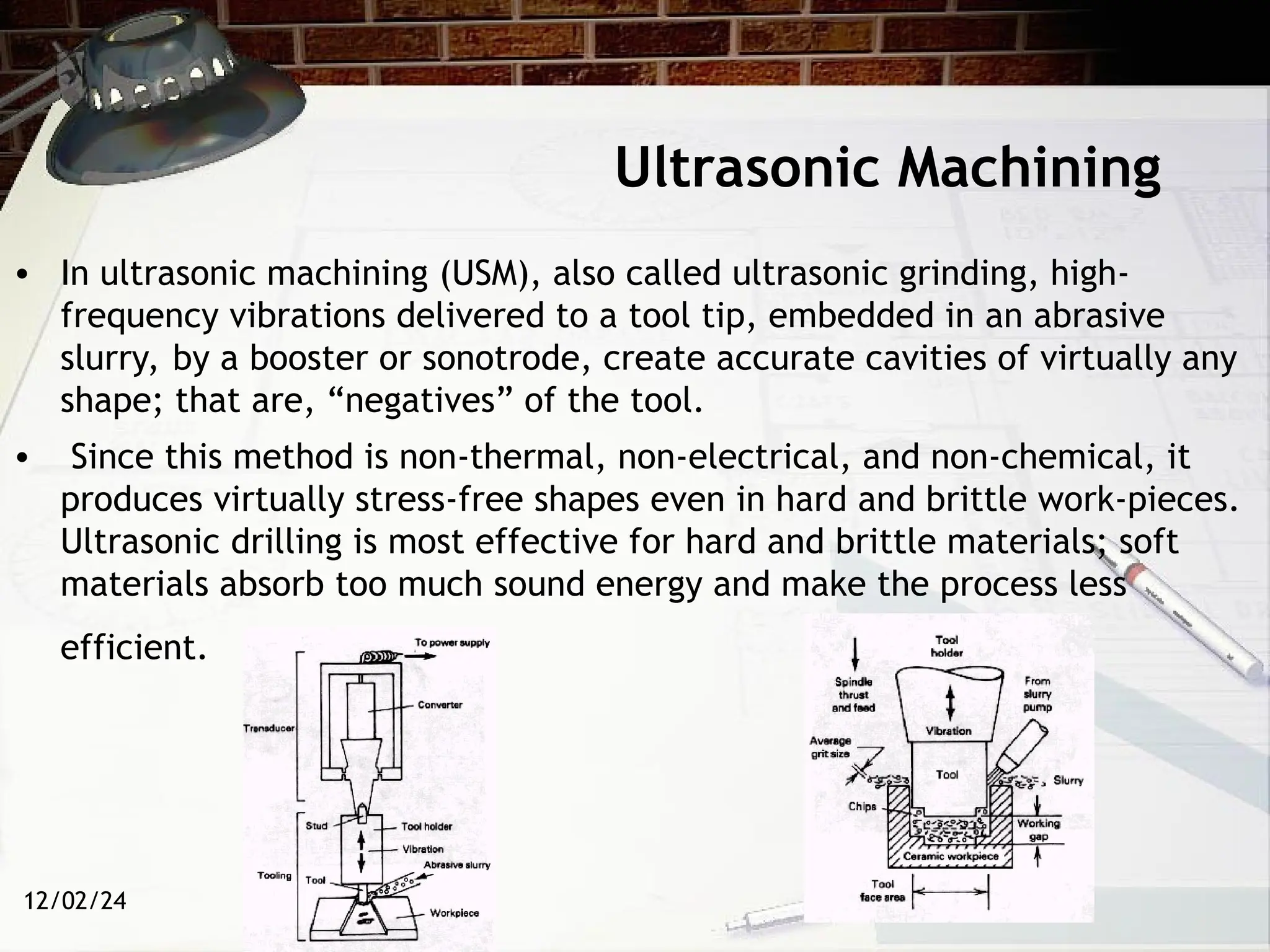
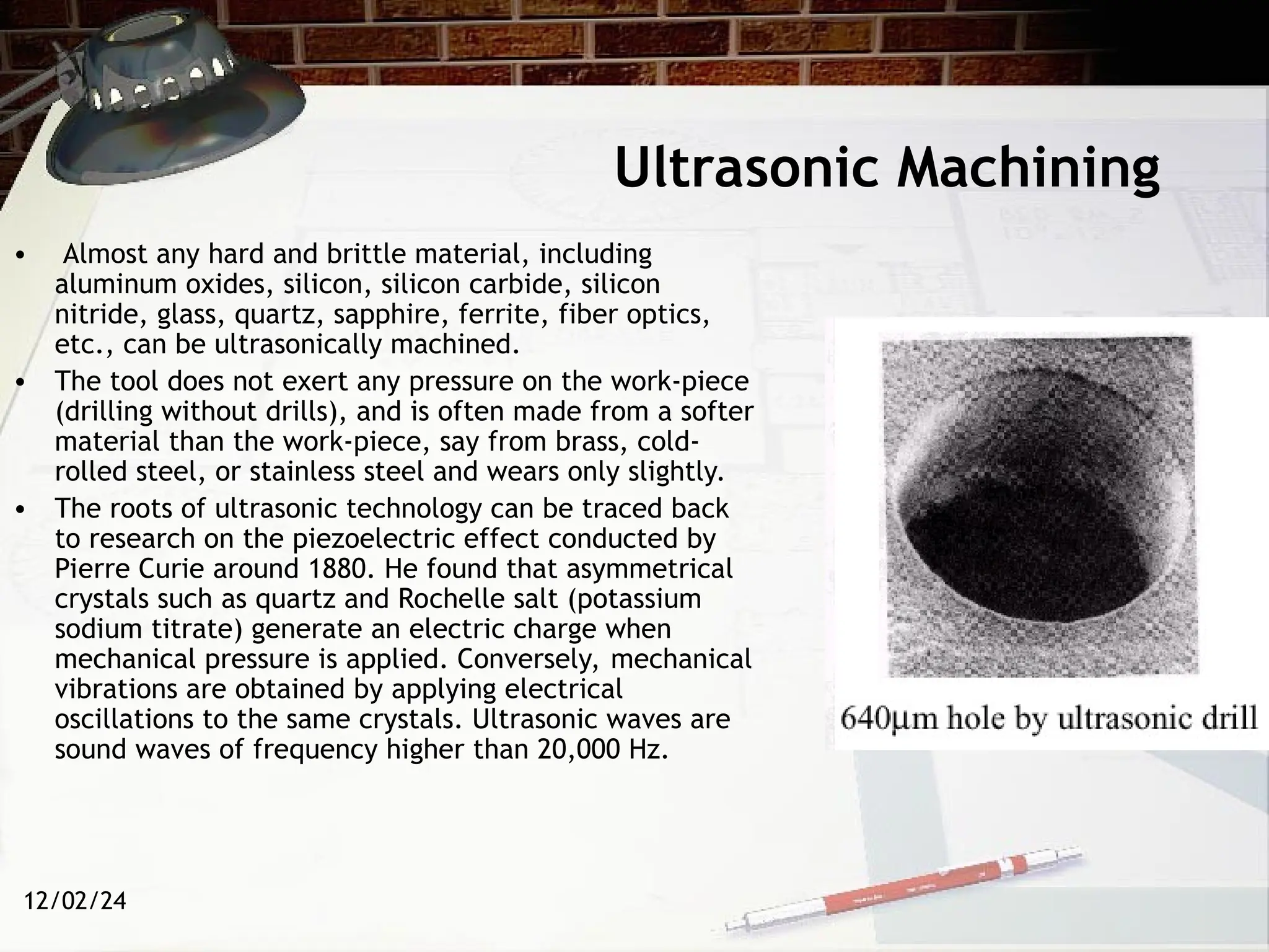
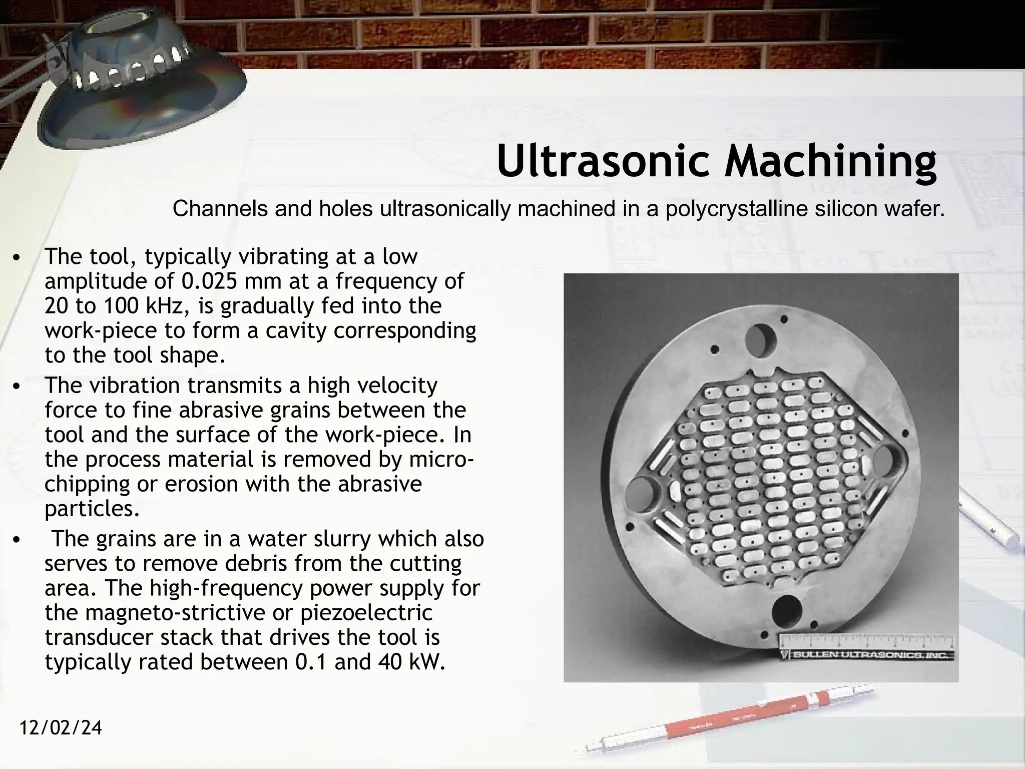
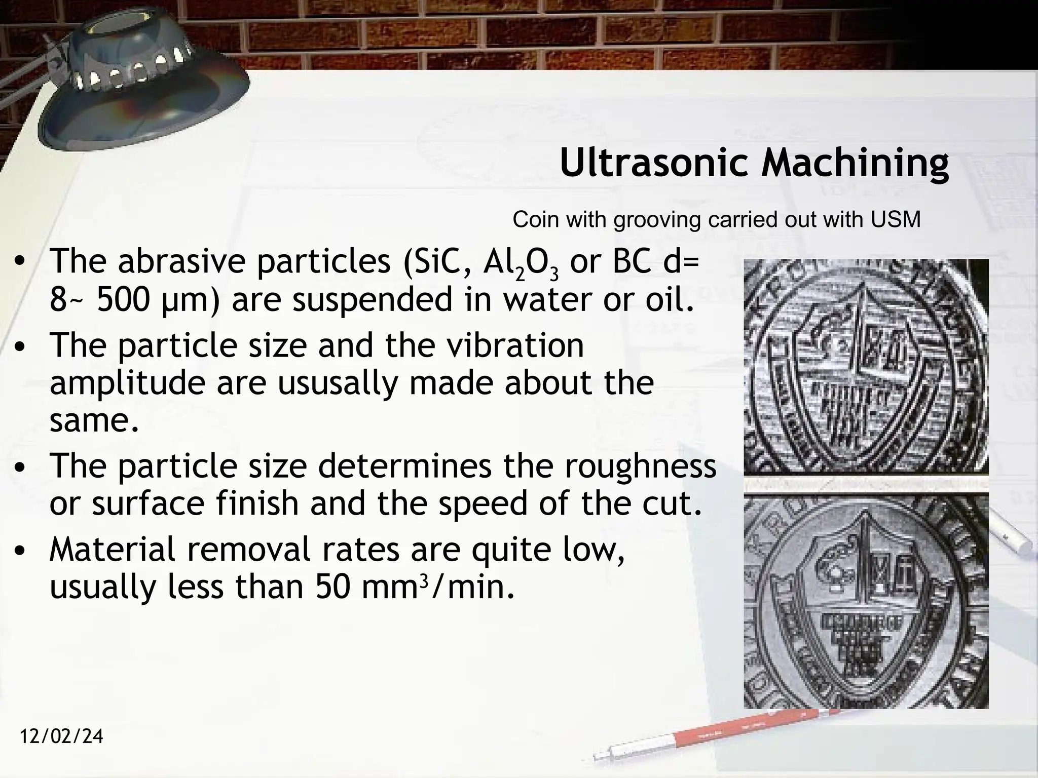
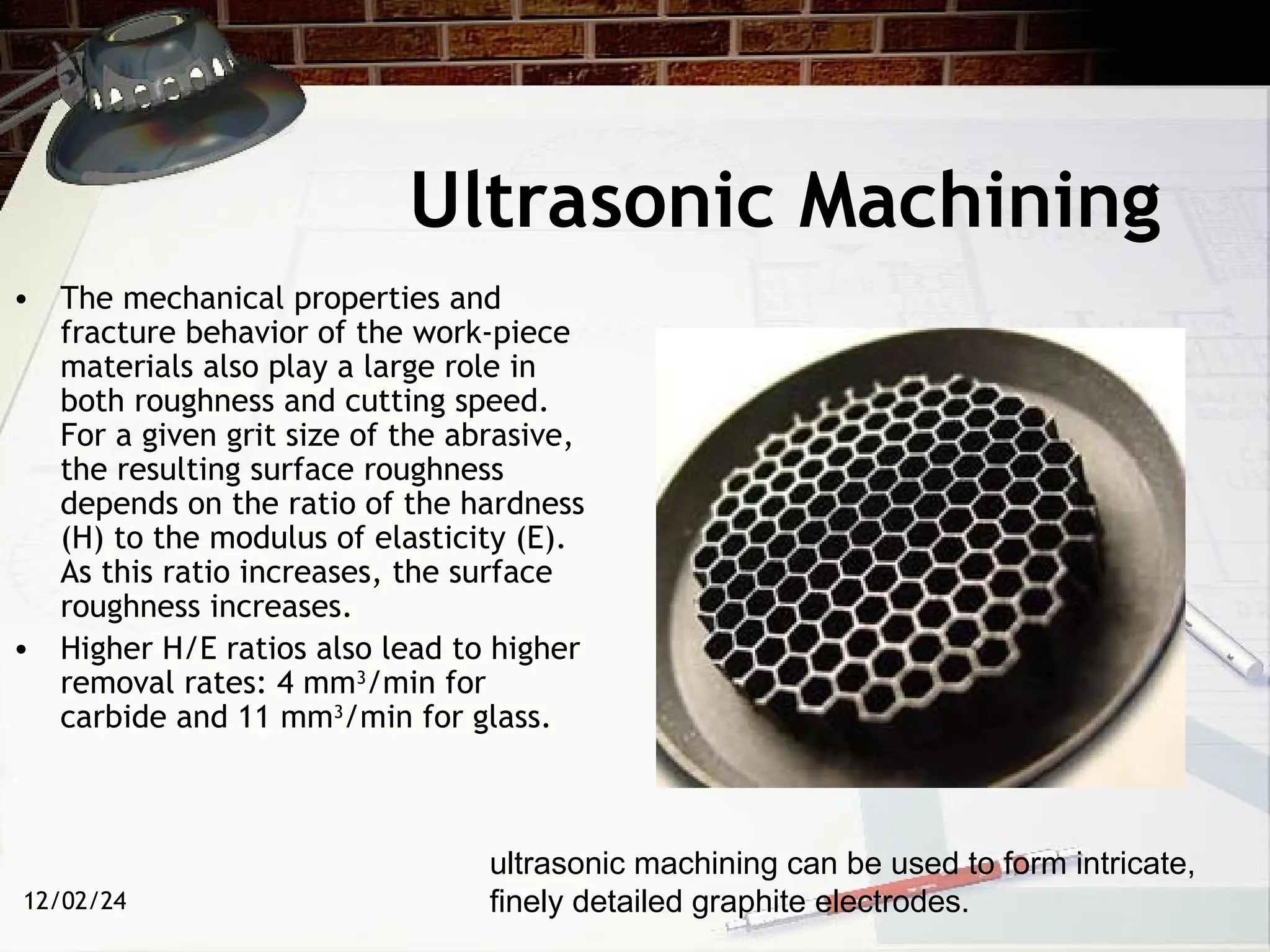
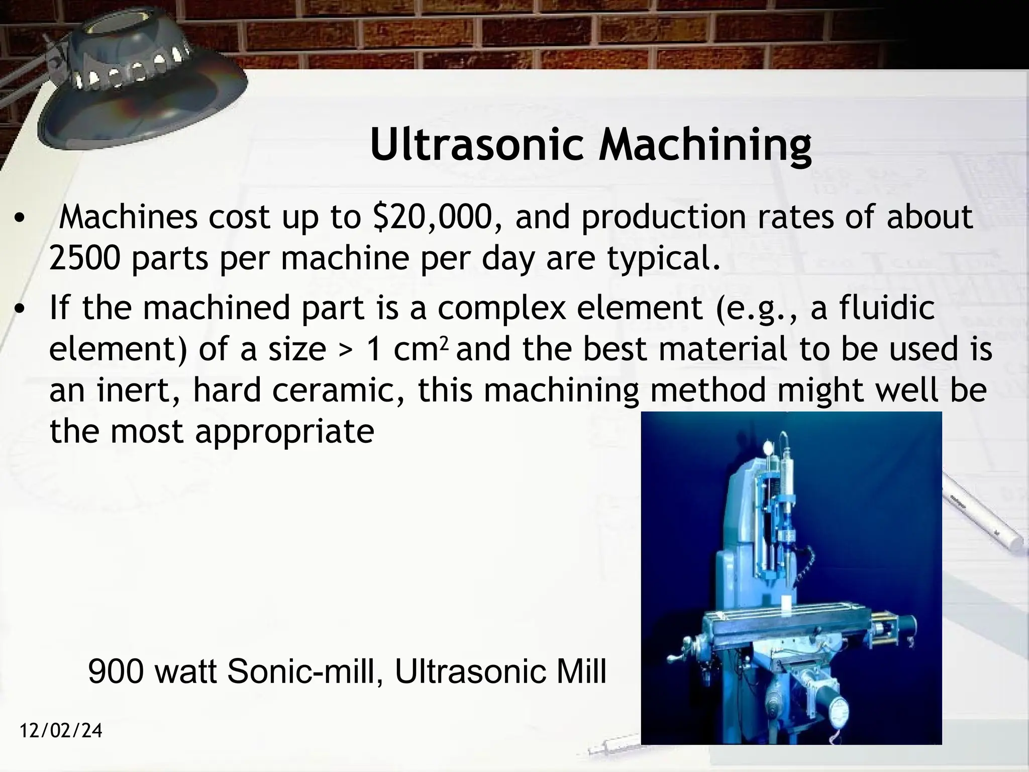
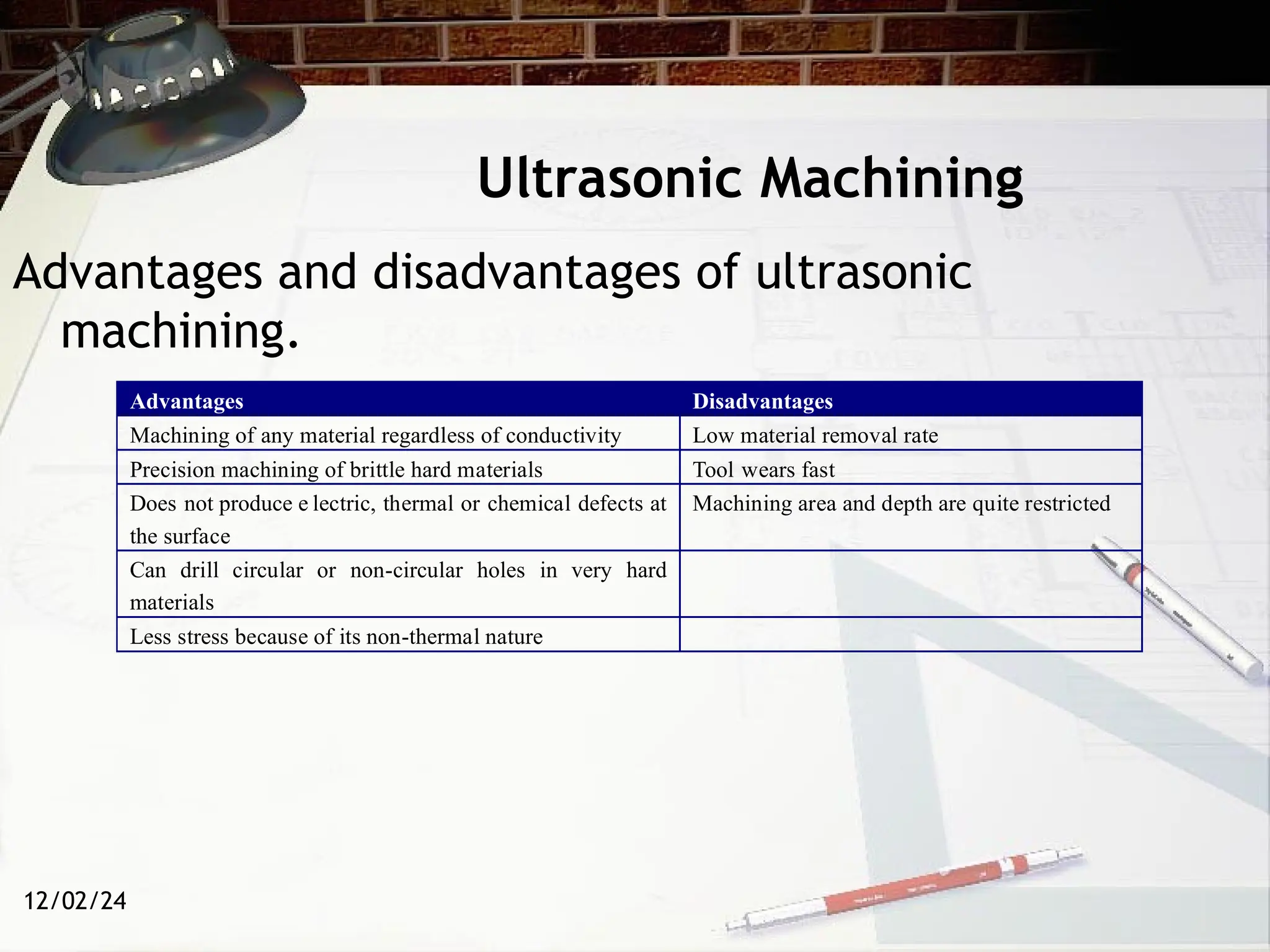
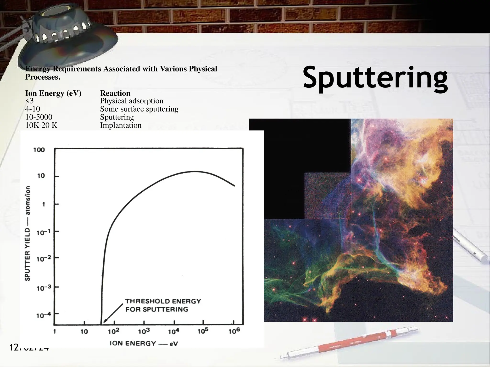
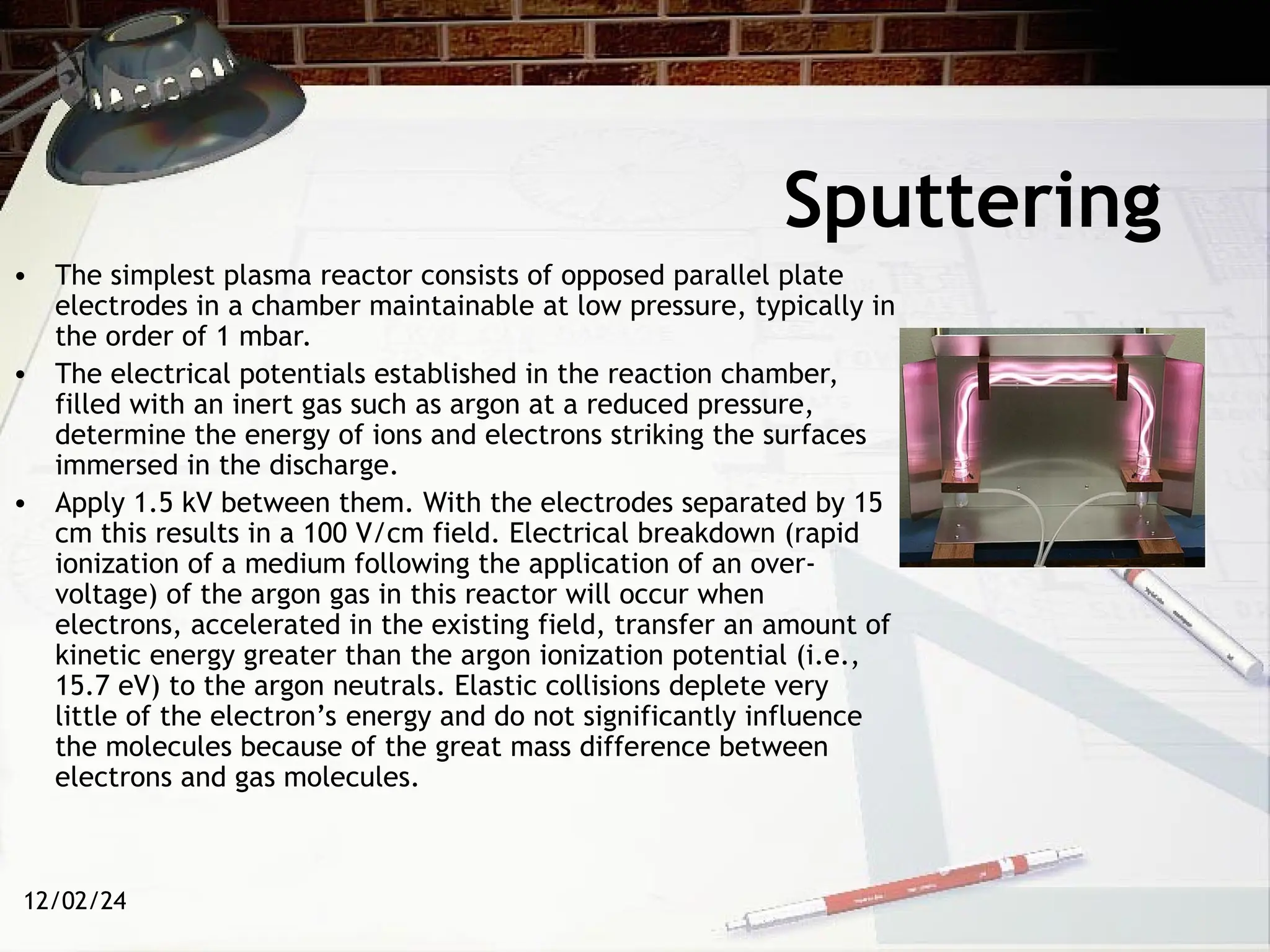
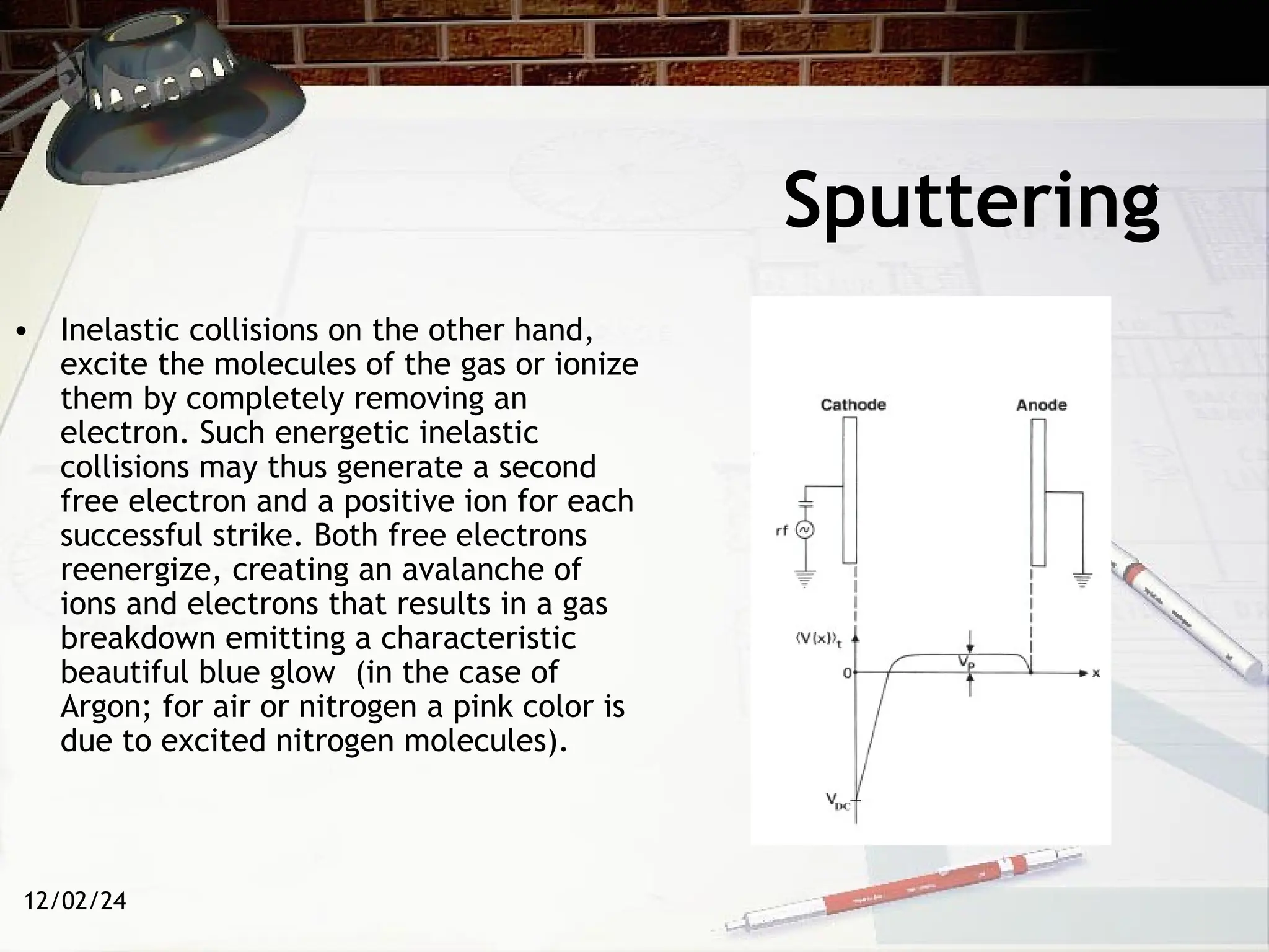
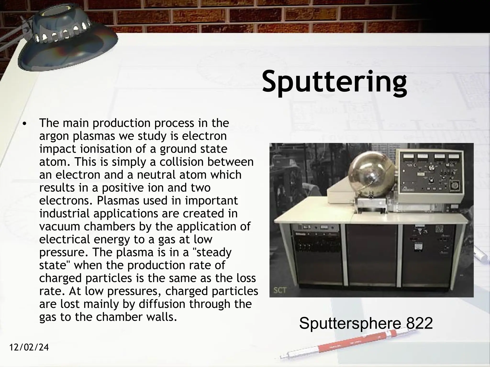
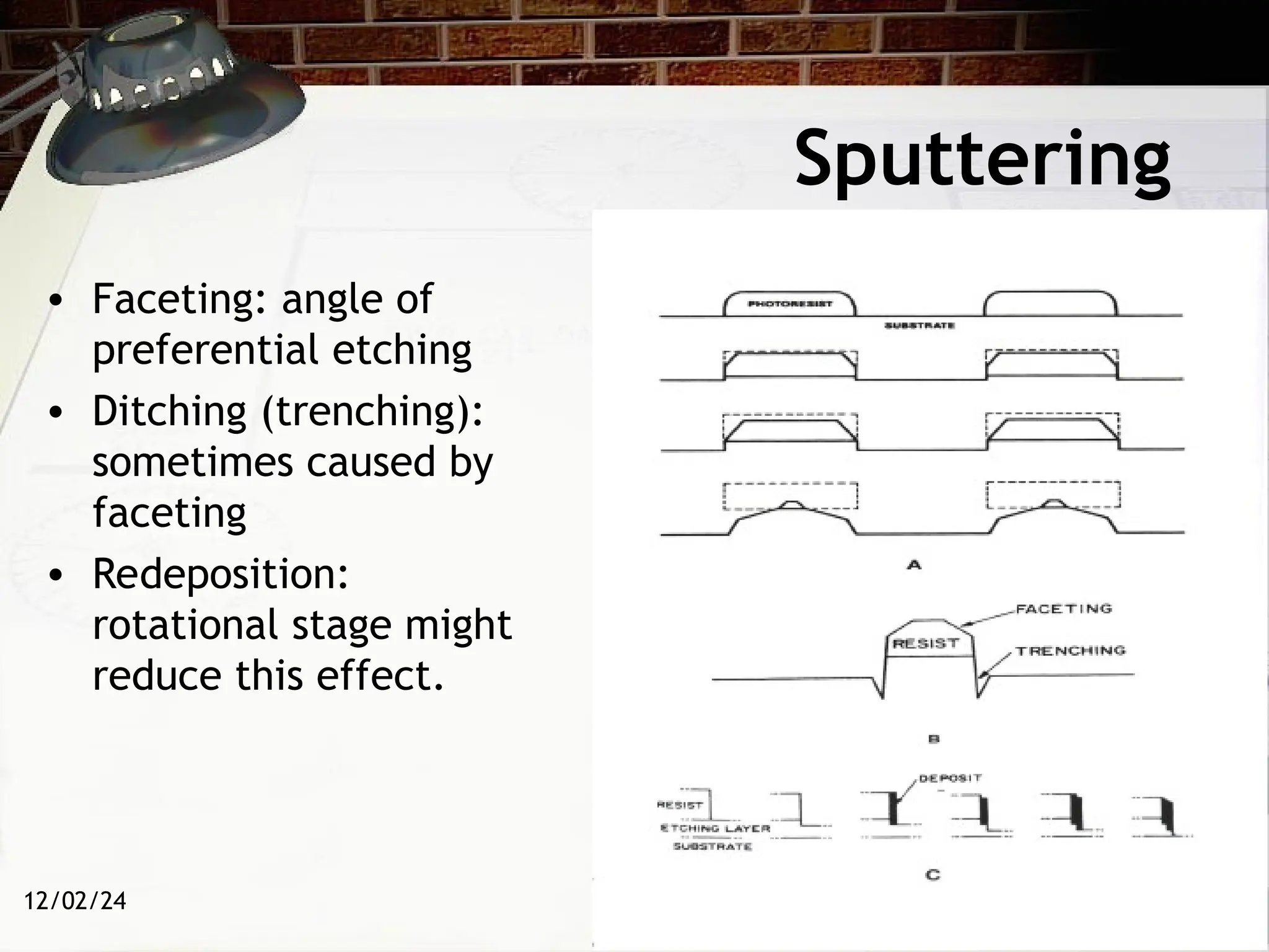
12/02/24
Advanced
Manufacturing
Choices
MAE 165-265
Spring 2013, Dr. Marc Madou
Class 4
12/02/24
Table of Content
• Mechanical Removing Techniques
– Ultrasonic Machining (USM)
– Sputtering and Focused Ion Beam Milling
(FIB)
12/02/24
Ultrasonic Machining
• In ultrasonic machining (USM), also called ultrasonic grinding, high-
frequency vibrations delivered to a tool tip, embedded in an abrasive
slurry, by a booster or sonotrode, create accurate cavities of virtually any
shape; that are, “negatives” of the tool.
• Since this method is non-thermal, non-electrical, and non-chemical, it
produces virtually stress-free shapes even in hard and brittle work-pieces.
Ultrasonic drilling is most effective for hard and brittle materials; soft
materials absorb too much sound energy and make the process less
efficient.
12/02/24
Ultrasonic Machining
• Almost any hard and brittle material, including
aluminum oxides, silicon, silicon carbide, silicon
nitride, glass, quartz, sapphire, ferrite, fiber optics,
etc., can be ultrasonically machined.
• The tool does not exert any pressure on the work-piece
(drilling without drills), and is often made from a softer
material than the work-piece, say from brass, cold-
rolled steel, or stainless steel and wears only slightly.
• The roots of ultrasonic technology can be traced back
to research on the piezoelectric effect conducted by
Pierre Curie around 1880. He found that asymmetrical
crystals such as quartz and Rochelle salt (potassium
sodium titrate) generate an electric charge when
mechanical pressure is applied. Conversely, mechanical
vibrations are obtained by applying electrical
oscillations to the same crystals. Ultrasonic waves are
sound waves of frequency higher than 20,000 Hz.
12/02/24
Ultrasonic Machining
• The tool, typically vibrating at a low
amplitude of 0.025 mm at a frequency of
20 to 100 kHz, is gradually fed into the
work-piece to form a cavity corresponding
to the tool shape.
• The vibration transmits a high velocity
force to fine abrasive grains between the
tool and the surface of the work-piece. In
the process material is removed by micro-
chipping or erosion with the abrasive
particles.
• The grains are in a water slurry which also
serves to remove debris from the cutting
area. The high-frequency power supply for
the magneto-strictive or piezoelectric
transducer stack that drives the tool is
typically rated between 0.1 and 40 kW.
Channels and holes ultrasonically machined in a polycrystalline silicon wafer.
12/02/24
Ultrasonic Machining
• The abrasive particles (SiC, Al2O3 or BC d=
8~ 500 µm) are suspended in water or oil.
• The particle size and the vibration
amplitude are ususally made about the
same.
• The particle size determines the roughness
or surface finish and the speed of the cut.
• Material removal rates are quite low,
usually less than 50 mm3
/min.
Coin with grooving carried out with USM
12/02/24
Ultrasonic Machining
• The mechanical properties and
fracture behavior of the work-piece
materials also play a large role in
both roughness and cutting speed.
For a given grit size of the abrasive,
the resulting surface roughness
depends on the ratio of the hardness
(H) to the modulus of elasticity (E).
As this ratio increases, the surface
roughness increases.
• Higher H/E ratios also lead to higher
removal rates: 4 mm3
/min for
carbide and 11 mm3
/min for glass.
ultrasonic machining can be used to form intricate,
finely detailed graphite electrodes.
12/02/24
Ultrasonic Machining
• Machines cost up to $20,000, and production rates of about
2500 parts per machine per day are typical.
• If the machined part is a complex element (e.g., a fluidic
element) of a size > 1 cm2
and the best material to be used is
an inert, hard ceramic, this machining method might well be
the most appropriate
900 watt Sonic-mill, Ultrasonic Mill
12/02/24
Ultrasonic Machining
Advantages and disadvantages of ultrasonic
machining.
Advantages Disadvantages
Machining of any material regardless of conductivity Low material removal rate
Precision machining of brittle hard materials Tool wears fast
Does not produce e lectric, thermal or chemical defects at
the surface
Machining area and depth are quite restricted
Can drill circular or non-circular holes in very hard
materials
Less stress because of its non-thermal nature
12/02/24
Sputtering
• Talking about sputtering we usually mean the usage of the phenomena
which are going on at the surface of solids (target) exposed in vacuum
under the directed flow of atomic particles - ions or neutrals. Ions are
extracted from gas discharge plasma as a spatially restricted beam and
accelerated by the electric field to the required energies.
• Usually for the purposes of sputtering we use the energy band from about
100 eV to 5000 eV (for ion implantation, energies up to a few tens keV
may be used) (see figure on next slide).
• What happens when ions with energy 0,1 - 5 keV bombard the surface of
the solid target? (The velocities of ions with such energies in vacuum may
be about a few tens thousand meters per second!).They can knock out
atoms from the work-piece.
12/02/24
Sputtering
Energy Requirements Associated with Various Physical
Processes.
Ion Energy (eV) Reaction
<3 Physical adsorption
4-10 Some surface sputtering
10-5000 Sputtering
10K-20 K Implantation
12/02/24
Sputtering
• The simplest plasma reactor consists of opposed parallel plate
electrodes in a chamber maintainable at low pressure, typically in
the order of 1 mbar.
• The electrical potentials established in the reaction chamber,
filled with an inert gas such as argon at a reduced pressure,
determine the energy of ions and electrons striking the surfaces
immersed in the discharge.
• Apply 1.5 kV between them. With the electrodes separated by 15
cm this results in a 100 V/cm field. Electrical breakdown (rapid
ionization of a medium following the application of an over-
voltage) of the argon gas in this reactor will occur when
electrons, accelerated in the existing field, transfer an amount of
kinetic energy greater than the argon ionization potential (i.e.,
15.7 eV) to the argon neutrals. Elastic collisions deplete very
little of the electron’s energy and do not significantly influence
the molecules because of the great mass difference between
electrons and gas molecules.
12/02/24
Sputtering
• Inelastic collisions on the other hand,
excite the molecules of the gas or ionize
them by completely removing an
electron. Such energetic inelastic
collisions may thus generate a second
free electron and a positive ion for each
successful strike. Both free electrons
reenergize, creating an avalanche of
ions and electrons that results in a gas
breakdown emitting a characteristic
beautiful blue glow (in the case of
Argon; for air or nitrogen a pink color is
due to excited nitrogen molecules).
12/02/24
Sputtering
• The main production process in the
argon plasmas we study is electron
impact ionisation of a ground state
atom. This is simply a collision between
an electron and a neutral atom which
results in a positive ion and two
electrons. Plasmas used in important
industrial applications are created in
vacuum chambers by the application of
electrical energy to a gas at low
pressure. The plasma is in a "steady
state" when the production rate of
charged particles is the same as the loss
rate. At low pressures, charged particles
are lost mainly by diffusion through the
gas to the chamber walls.
Sputtersphere 822
12/02/24
Sputtering
• Faceting: angle of
preferential etching
• Ditching (trenching):
sometimes caused by
faceting
• Redeposition:
rotational stage might
reduce this effect.
12/02/24
Sputtering
• In case the direction of momentum propagation in the target (work-piece)
changes : (a) the depths of the disturbed zone changes and (b) the surface
zone where the atoms are sputtered from changes.
• It can be shows that the number of sputtered atoms will increase when the
angle becomes larger than 0°. But when the angle becomes close to 90°,
ions start practically to slide along the surface and the energy and
momentum transferred to the target's atoms decrease. Correspondingly
the number of sputtered atoms decreases too.
• The number of atoms sputtered by one incident ion is called the
"sputtering yield". So the angular dependence of sputtering yield S should
be like shown below.
12/02/24
Sputtering
12/02/24
Focused Ion Beam Milling (FIB)
• Focused ion beam, also known as FIB, is a technique used
particularly in the semiconductor and materials science fields for
site-specific analysis, deposition, and ablation of materials.
• The FIB is a scientific instrument that resembles a scanning
electron microscope. However, while the SEM uses a focused beam
of electrons to image the sample in the chamber, a FIB instead
uses a focused beam of ions.
• Gallium ions are accelerated to an energy of 5-50 keV
(kiloelectronvolts), and then focused onto the sample by
electrostatic lenses. A modern FIB can deliver tens of nanoamps of
current to a sample and can image the sample with a spot size on
the order of a few nanometers.
12/02/24
• Because of the sputtering capability, the FIB
is used as a micro-machining tool, to modify
or machine materials at the micro- and
nanoscale. FIB micro machining has become a
broad field of its own, but nano machining
with FIB is a field that still needs developing.
• The common smallest beam size is 4-6 nm.
FIB tools are designed to etch or machine
surfaces, an ideal FIB might machine away
one atom layer without any disruption of the
atoms in the next layer, or any residual
disruptions above the surface.
Focused Ion Beam Milling (FIB)
12/02/24
Focused Ion Beam Milling (FIB)
http://www.youtube.com/watch?
v=VV90xM3QTcM

Advanced Manufacturing Choices Ultrasonic machining process

  • 1.
  • 2.
    12/02/24 Table of Content •Mechanical Removing Techniques – Ultrasonic Machining (USM) – Sputtering and Focused Ion Beam Milling (FIB)
  • 3.
    12/02/24 Ultrasonic Machining • Inultrasonic machining (USM), also called ultrasonic grinding, high- frequency vibrations delivered to a tool tip, embedded in an abrasive slurry, by a booster or sonotrode, create accurate cavities of virtually any shape; that are, “negatives” of the tool. • Since this method is non-thermal, non-electrical, and non-chemical, it produces virtually stress-free shapes even in hard and brittle work-pieces. Ultrasonic drilling is most effective for hard and brittle materials; soft materials absorb too much sound energy and make the process less efficient.
  • 4.
    12/02/24 Ultrasonic Machining • Almostany hard and brittle material, including aluminum oxides, silicon, silicon carbide, silicon nitride, glass, quartz, sapphire, ferrite, fiber optics, etc., can be ultrasonically machined. • The tool does not exert any pressure on the work-piece (drilling without drills), and is often made from a softer material than the work-piece, say from brass, cold- rolled steel, or stainless steel and wears only slightly. • The roots of ultrasonic technology can be traced back to research on the piezoelectric effect conducted by Pierre Curie around 1880. He found that asymmetrical crystals such as quartz and Rochelle salt (potassium sodium titrate) generate an electric charge when mechanical pressure is applied. Conversely, mechanical vibrations are obtained by applying electrical oscillations to the same crystals. Ultrasonic waves are sound waves of frequency higher than 20,000 Hz.
  • 5.
    12/02/24 Ultrasonic Machining • Thetool, typically vibrating at a low amplitude of 0.025 mm at a frequency of 20 to 100 kHz, is gradually fed into the work-piece to form a cavity corresponding to the tool shape. • The vibration transmits a high velocity force to fine abrasive grains between the tool and the surface of the work-piece. In the process material is removed by micro- chipping or erosion with the abrasive particles. • The grains are in a water slurry which also serves to remove debris from the cutting area. The high-frequency power supply for the magneto-strictive or piezoelectric transducer stack that drives the tool is typically rated between 0.1 and 40 kW. Channels and holes ultrasonically machined in a polycrystalline silicon wafer.
  • 6.
    12/02/24 Ultrasonic Machining • Theabrasive particles (SiC, Al2O3 or BC d= 8~ 500 µm) are suspended in water or oil. • The particle size and the vibration amplitude are ususally made about the same. • The particle size determines the roughness or surface finish and the speed of the cut. • Material removal rates are quite low, usually less than 50 mm3 /min. Coin with grooving carried out with USM
  • 7.
    12/02/24 Ultrasonic Machining • Themechanical properties and fracture behavior of the work-piece materials also play a large role in both roughness and cutting speed. For a given grit size of the abrasive, the resulting surface roughness depends on the ratio of the hardness (H) to the modulus of elasticity (E). As this ratio increases, the surface roughness increases. • Higher H/E ratios also lead to higher removal rates: 4 mm3 /min for carbide and 11 mm3 /min for glass. ultrasonic machining can be used to form intricate, finely detailed graphite electrodes.
  • 8.
    12/02/24 Ultrasonic Machining • Machinescost up to $20,000, and production rates of about 2500 parts per machine per day are typical. • If the machined part is a complex element (e.g., a fluidic element) of a size > 1 cm2 and the best material to be used is an inert, hard ceramic, this machining method might well be the most appropriate 900 watt Sonic-mill, Ultrasonic Mill
  • 9.
    12/02/24 Ultrasonic Machining Advantages anddisadvantages of ultrasonic machining. Advantages Disadvantages Machining of any material regardless of conductivity Low material removal rate Precision machining of brittle hard materials Tool wears fast Does not produce e lectric, thermal or chemical defects at the surface Machining area and depth are quite restricted Can drill circular or non-circular holes in very hard materials Less stress because of its non-thermal nature
  • 10.
    12/02/24 Sputtering • Talking aboutsputtering we usually mean the usage of the phenomena which are going on at the surface of solids (target) exposed in vacuum under the directed flow of atomic particles - ions or neutrals. Ions are extracted from gas discharge plasma as a spatially restricted beam and accelerated by the electric field to the required energies. • Usually for the purposes of sputtering we use the energy band from about 100 eV to 5000 eV (for ion implantation, energies up to a few tens keV may be used) (see figure on next slide). • What happens when ions with energy 0,1 - 5 keV bombard the surface of the solid target? (The velocities of ions with such energies in vacuum may be about a few tens thousand meters per second!).They can knock out atoms from the work-piece.
  • 11.
    12/02/24 Sputtering Energy Requirements Associatedwith Various Physical Processes. Ion Energy (eV) Reaction <3 Physical adsorption 4-10 Some surface sputtering 10-5000 Sputtering 10K-20 K Implantation
  • 12.
    12/02/24 Sputtering • The simplestplasma reactor consists of opposed parallel plate electrodes in a chamber maintainable at low pressure, typically in the order of 1 mbar. • The electrical potentials established in the reaction chamber, filled with an inert gas such as argon at a reduced pressure, determine the energy of ions and electrons striking the surfaces immersed in the discharge. • Apply 1.5 kV between them. With the electrodes separated by 15 cm this results in a 100 V/cm field. Electrical breakdown (rapid ionization of a medium following the application of an over- voltage) of the argon gas in this reactor will occur when electrons, accelerated in the existing field, transfer an amount of kinetic energy greater than the argon ionization potential (i.e., 15.7 eV) to the argon neutrals. Elastic collisions deplete very little of the electron’s energy and do not significantly influence the molecules because of the great mass difference between electrons and gas molecules.
  • 13.
    12/02/24 Sputtering • Inelastic collisionson the other hand, excite the molecules of the gas or ionize them by completely removing an electron. Such energetic inelastic collisions may thus generate a second free electron and a positive ion for each successful strike. Both free electrons reenergize, creating an avalanche of ions and electrons that results in a gas breakdown emitting a characteristic beautiful blue glow (in the case of Argon; for air or nitrogen a pink color is due to excited nitrogen molecules).
  • 14.
    12/02/24 Sputtering • The mainproduction process in the argon plasmas we study is electron impact ionisation of a ground state atom. This is simply a collision between an electron and a neutral atom which results in a positive ion and two electrons. Plasmas used in important industrial applications are created in vacuum chambers by the application of electrical energy to a gas at low pressure. The plasma is in a "steady state" when the production rate of charged particles is the same as the loss rate. At low pressures, charged particles are lost mainly by diffusion through the gas to the chamber walls. Sputtersphere 822
  • 15.
    12/02/24 Sputtering • Faceting: angleof preferential etching • Ditching (trenching): sometimes caused by faceting • Redeposition: rotational stage might reduce this effect.
  • 16.
    12/02/24 Sputtering • In casethe direction of momentum propagation in the target (work-piece) changes : (a) the depths of the disturbed zone changes and (b) the surface zone where the atoms are sputtered from changes. • It can be shows that the number of sputtered atoms will increase when the angle becomes larger than 0°. But when the angle becomes close to 90°, ions start practically to slide along the surface and the energy and momentum transferred to the target's atoms decrease. Correspondingly the number of sputtered atoms decreases too. • The number of atoms sputtered by one incident ion is called the "sputtering yield". So the angular dependence of sputtering yield S should be like shown below.
  • 17.
  • 18.
    12/02/24 Focused Ion BeamMilling (FIB) • Focused ion beam, also known as FIB, is a technique used particularly in the semiconductor and materials science fields for site-specific analysis, deposition, and ablation of materials. • The FIB is a scientific instrument that resembles a scanning electron microscope. However, while the SEM uses a focused beam of electrons to image the sample in the chamber, a FIB instead uses a focused beam of ions. • Gallium ions are accelerated to an energy of 5-50 keV (kiloelectronvolts), and then focused onto the sample by electrostatic lenses. A modern FIB can deliver tens of nanoamps of current to a sample and can image the sample with a spot size on the order of a few nanometers.
  • 19.
    12/02/24 • Because ofthe sputtering capability, the FIB is used as a micro-machining tool, to modify or machine materials at the micro- and nanoscale. FIB micro machining has become a broad field of its own, but nano machining with FIB is a field that still needs developing. • The common smallest beam size is 4-6 nm. FIB tools are designed to etch or machine surfaces, an ideal FIB might machine away one atom layer without any disruption of the atoms in the next layer, or any residual disruptions above the surface. Focused Ion Beam Milling (FIB)
  • 20.
    12/02/24 Focused Ion BeamMilling (FIB) http://www.youtube.com/watch? v=VV90xM3QTcM