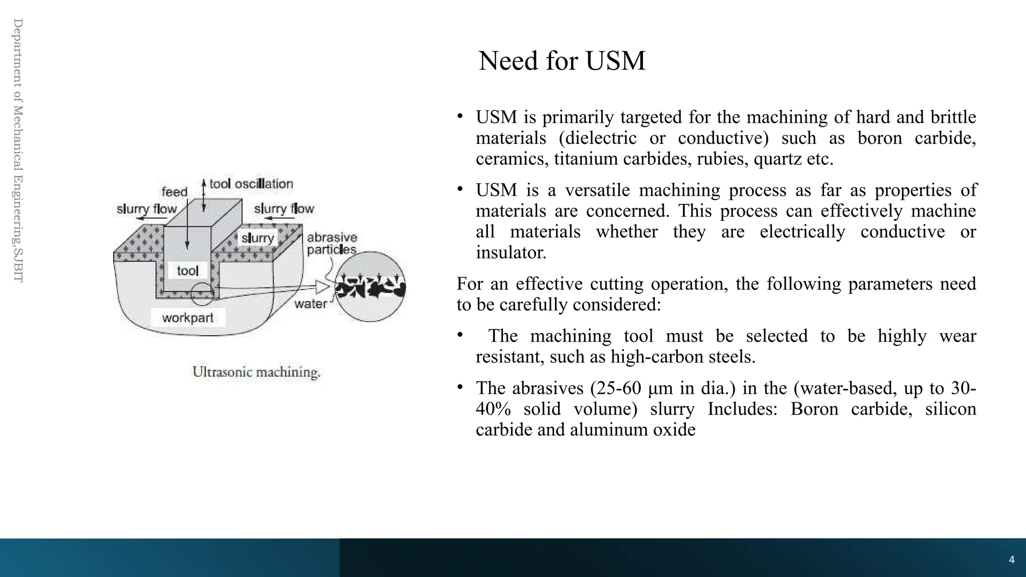
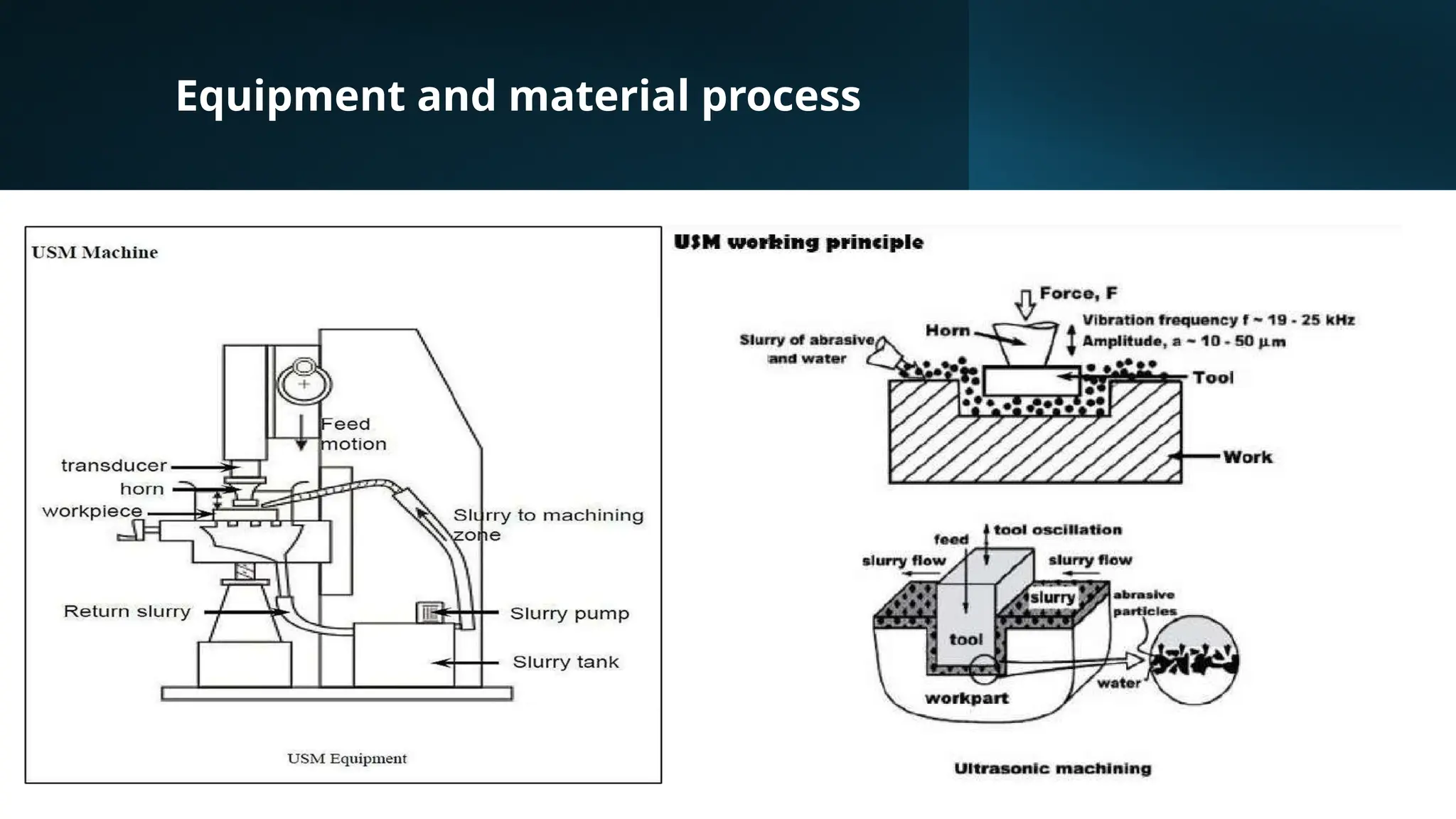
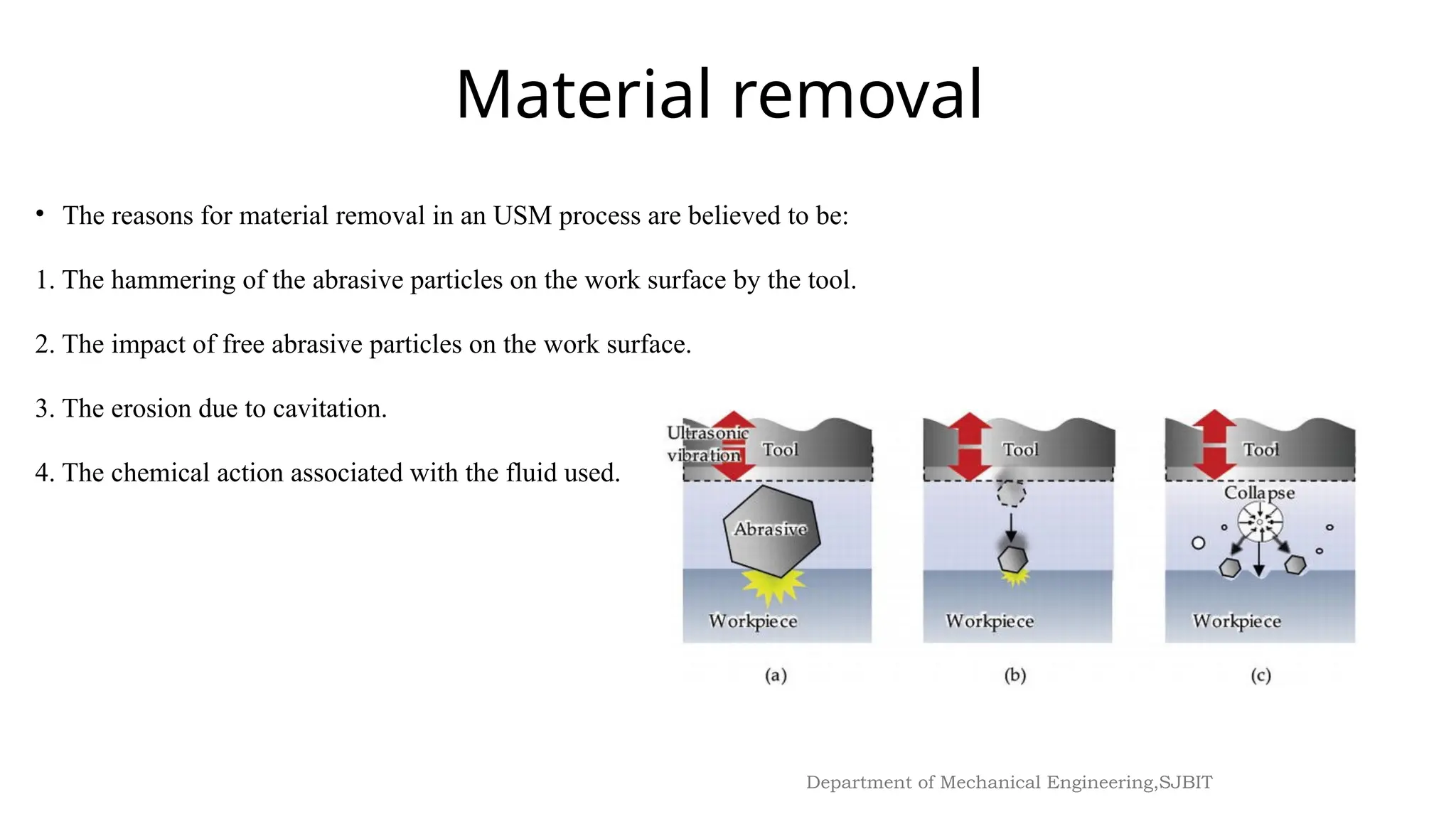
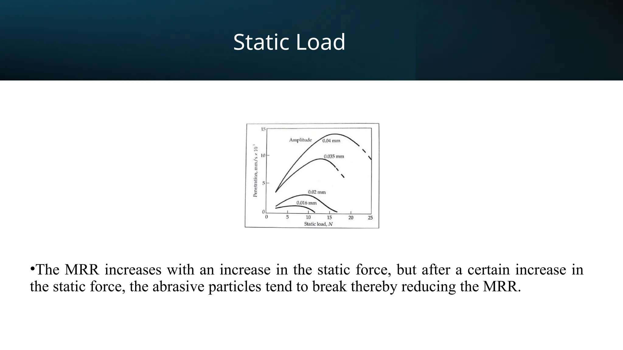
ULTRASONIC MACHINING (USM),
ABRASIVE JET MACHINING (AJM)
Module 2
Introduction to
Ultrasonic
Machining
(USM)
USM is mechanical material removal process, or an
abrasive process used to erode holes or cavities on
hard or brittle work piece by using shaped tools, high
frequency mechanical motion and an abrasive slurry.
USM offers a solution to the expanding need for
machining brittle materials such as single crystals,
glasses and polycrystalline ceramics and increasing
complex operations to provide intricate shapes and
workpiece profiles
Ultrasonic Machining (USM)
• Ultrasonic Machining is a non- traditional process, in which abrasives contained in a slurry are driven
against the work by a tool oscillating at low amplitude (25-100 μm) and high frequency (15-30 KHz):
• The process was first developed in 1950s and was originally used for finishing EDM surfaces. The
basic process is that a ductile and tough tool is pushed against the work with a constant force.
• A constant stream of abrasive slurry passes between the tool and the work (gap is 25-40 μm) to
provide abrasives and carry away chips.
• The majority of the cutting action comes from an ultrasonic (cyclic) force applied
Need for USM
Department
of
Mechanical
Engineering,SJBIT
• USM is primarily targeted for the machining of hard and brittle
materials (dielectric or conductive) such as boron carbide,
ceramics, titanium carbides, rubies, quartz etc.
• USM is a versatile machining process as far as properties of
materials are concerned. This process can effectively machine
all materials whether they are electrically conductive or
insulator.
For an effective cutting operation, the following parameters need
to be carefully considered:
• The machining tool must be selected to be highly wear
resistant, such as high-carbon steels.
• The abrasives (25-60 μm in dia.) in the (water-based, up to 30-
40% solid volume) slurry Includes: Boron carbide, silicon
carbide and aluminum oxide
4
Equipment and material process
USM equipment
Major components
• Power supply
• Transducer
• Tool Holder & horn
• Tool
• Abrasive
Working of horn as mechanical
amplifier of amplitude of vibration
• The ultrasonic vibrations are
produced by the transducer. The
transducer is driven by suitable signal
generator followed by power
amplifier.
• The transducer for USM works on the
following principle
• Piezoelectric effect
• Magnetostrictive effect
• High Power sine wave generator:​
• This unit converts low frequency (60 Hz) electrical power to high frequency
(20kHz) electrical power.​
• Transducer​
• The high frequency electrical signal is transmitted to traducer which converts
it into high frequency low amplitude vibration. Essentially transducer
converts electrical energy to mechanical vibration. There are two types of
transducer used​
• Piezo electric transducer​
• Magneto-stricitve transducer.
• Tool Holder:​
• The tool holder holds and connects the tool to the transducer. It virtually
transmits the energy and, in some cases, amplifies the amplitude of vibration.
Material of tool should have good acoustic properties, high resistance to
fatigue cracking.​
• Commonly used tool holders are Monel, titanium, stainless steel. Tool
holders are more expensive, demand higher operating cost​
USM equipment
• Tool:​
Tools are made of relatively ductile materials like Brass, Stainless steel
or Mild steel so that Tool wear rate (TWR) can be minimized. The
value of ratio of TWR and MRR depends on kind of abrasive, work
material and tool materials.​
Abrasive Slurry
• The most common abrasives are Boron Carbide (B4C),​
• Silicon Carbide (SiC), Corrundum (Al2O3), Diamond and Boron
silicarbide.​
• B4C is the best and most efficient among the rest but it is expensive.​
• SiC is used on glass, germanium and most ceramics.​
• Cutting time with SiC is about 20-40% more than that with B4C.​
• Diamond dust is used only for cutting daimond and rubies.​
• Water is the most commonly used fluid although other liquids such
as benzene, glycerol and oils are also used.​
USM equipment
10
Department of Mechanical Engineering,SJBIT
• The reasons for material removal in an USM process are believed to be:
1. The hammering of the abrasive particles on the work surface by the tool.
2. The impact of free abrasive particles on the work surface.
3. The erosion due to cavitation.
4. The chemical action associated with the fluid used.
Material removal
Process Variable
Process variables
o Amplitude of vibration (ao) – 15 – 50 μm
o Frequency of vibration (f) – 19 – 25 kHz
o Feed force (F) – related to tool dimensions
o Feed pressure (p)
o Abrasive size – 15 μm – 150 μm
o Abrasive material
- Al2O3
- SiC
- B4C
- Diamond
o Flow strength of work material
o Flow strength of the tool material
o Contact area of the tool – A
o Volume concentration of abrasive in water slurry – C
Effect of process parameters
• Amplitude & frequency of
vibration of the tool
• Slurry
• Tool & Work material
• Type of abrasive
• Abrasive Size
• Feed force
Amplitude &
frequency of
vibration of the tool
• It is clear that the MRR increases with an
increase in the frequency and the amplitude
of ultrasonic vibrations
• At large amplitudes, the kinetic energy
rises, this in turn enhances the mechanical
chipping action & increase MRR.
• But increasing the amplitude tends to
increase the surface roughness.
• The frequency and amplitude of vibration
ranges from 15-30kHz and 25-100µm
respectively.
Slurry
• The MRR increases proportional to the one-
fourth power of slurry concentration, i.e., C1/4
.
• However, the increasing trend continues till
concentration reaches 30%, beyond which an
increase in the concentration does not help.
• The improved flow of slurry results in an
enhanced machining rate.
• In practice, a volumetric concentration of
about 30 to 35% of abrasive is recommended.
• A change in concentration occurs during
machining because of the abrasive dust.
• Metal removal rate increases with increase in
slurry concentration.
• The machining rate reaches to an optimum
value with 30% slurry concentration
USM Process Parameter:
16
Department of Mechanical Engineering,SJBIT
 Type of abrasive and abrasive size
• The abrasive used should be harder than the
workpiece material being machined, else the
lifetime of it will be shortened resulting in poor
surface finish.
• Boron carbide is used for high MMR and hard
workpiece materials.
• The size of the abrasive particle varies between
240-800 grit.
• Coarse grades are suitable for high MRR but
results in rough surface finish.
Tool & Work
material
• The tool must withstand the
vibrations, it should not fail or
wear quickly.
• The harder the tool material the
faster its wear rate will be,
thereby leading to unfavorable
metal removal rate and surface
finish on the workpiece.
• Tough malleable material gives
satisfactory results.
Static Load
•The MRR increases with an increase in the static force, but after a certain increase in
the static force, the abrasive particles tend to break thereby reducing the MRR.
Process
Characteristics
• Metal Removal Rate
• Surface finish
• Accuracy
• Drilling hole capacity
Advantages
 Any materials can be machined regardless of their electrical conductivity.
 Especially suitable for machining of brittle materials.
 Machined parts by USM possess better surface finish and higher structural
integrity. USM does not produce thermal, electrical and chemical
abnormal surface.
 No burrs and no distortion of workpiece.
 Hard and brittle metals can be machined.
 Stresses are minimum.

Thin sheets can be machined.
 Investment cost is low.
 Power consumption is low
Disadvantage
s
 USM has higher power consumption and lower material-removal rates
than traditional fabrication processes.
 Tool wears fast in USM.
 Machining area and depth is restraint in USM.
 Depth of holes and cavities produced are small. Usually the depth of hole
is limited to 2.5 times the diameter of the tool. There is a tendency for
holes to break out at the bottom owing to high amplitude of vibrations of
the tool.
 Not suitable for soft workpiece material.
Applications
 Used for machining hard and brittle metallic alloys, semiconductors,
glass,ceramics, carbides etc.
 Used for machining round, square, irregular shaped holes and surface
impressions.
 Machining, wire drawing, punching or small blanking dies.
 Drilling and machining cavities or holes in conductive and non-conductive
materials like glass, ceramics etc.
 Used to machine hard materials like tool steel, tungsten and hard carbides.
 Threading of various glass and ceramic materials.
 Used for making tools and dies.
 Soft materials like non-ferrous metals and alloys and brittle materials can be
machined.
 Removing flash and parting lines from injection moulded parts.
 Deburring and polishing plastic, nylon and Teflon components.
 To produce high quality surface.
 Hard materials and precious stones such as synthetic ruby for the preparation
of jewels for watch and timer movements are successfully machined by this
method

USM is mechanical material removal process

  • 1.
    ULTRASONIC MACHINING (USM), ABRASIVEJET MACHINING (AJM) Module 2
  • 2.
    Introduction to Ultrasonic Machining (USM) USM ismechanical material removal process, or an abrasive process used to erode holes or cavities on hard or brittle work piece by using shaped tools, high frequency mechanical motion and an abrasive slurry. USM offers a solution to the expanding need for machining brittle materials such as single crystals, glasses and polycrystalline ceramics and increasing complex operations to provide intricate shapes and workpiece profiles
  • 3.
    Ultrasonic Machining (USM) •Ultrasonic Machining is a non- traditional process, in which abrasives contained in a slurry are driven against the work by a tool oscillating at low amplitude (25-100 μm) and high frequency (15-30 KHz): • The process was first developed in 1950s and was originally used for finishing EDM surfaces. The basic process is that a ductile and tough tool is pushed against the work with a constant force. • A constant stream of abrasive slurry passes between the tool and the work (gap is 25-40 μm) to provide abrasives and carry away chips. • The majority of the cutting action comes from an ultrasonic (cyclic) force applied
  • 4.
    Need for USM Department of Mechanical Engineering,SJBIT •USM is primarily targeted for the machining of hard and brittle materials (dielectric or conductive) such as boron carbide, ceramics, titanium carbides, rubies, quartz etc. • USM is a versatile machining process as far as properties of materials are concerned. This process can effectively machine all materials whether they are electrically conductive or insulator. For an effective cutting operation, the following parameters need to be carefully considered: • The machining tool must be selected to be highly wear resistant, such as high-carbon steels. • The abrasives (25-60 μm in dia.) in the (water-based, up to 30- 40% solid volume) slurry Includes: Boron carbide, silicon carbide and aluminum oxide 4
  • 5.
  • 6.
    USM equipment Major components •Power supply • Transducer • Tool Holder & horn • Tool • Abrasive
  • 7.
    Working of hornas mechanical amplifier of amplitude of vibration • The ultrasonic vibrations are produced by the transducer. The transducer is driven by suitable signal generator followed by power amplifier. • The transducer for USM works on the following principle • Piezoelectric effect • Magnetostrictive effect
  • 8.
    • High Powersine wave generator:​ • This unit converts low frequency (60 Hz) electrical power to high frequency (20kHz) electrical power.​ • Transducer​ • The high frequency electrical signal is transmitted to traducer which converts it into high frequency low amplitude vibration. Essentially transducer converts electrical energy to mechanical vibration. There are two types of transducer used​ • Piezo electric transducer​ • Magneto-stricitve transducer. • Tool Holder:​ • The tool holder holds and connects the tool to the transducer. It virtually transmits the energy and, in some cases, amplifies the amplitude of vibration. Material of tool should have good acoustic properties, high resistance to fatigue cracking.​ • Commonly used tool holders are Monel, titanium, stainless steel. Tool holders are more expensive, demand higher operating cost​ USM equipment
  • 9.
    • Tool:​ Tools aremade of relatively ductile materials like Brass, Stainless steel or Mild steel so that Tool wear rate (TWR) can be minimized. The value of ratio of TWR and MRR depends on kind of abrasive, work material and tool materials.​ Abrasive Slurry • The most common abrasives are Boron Carbide (B4C),​ • Silicon Carbide (SiC), Corrundum (Al2O3), Diamond and Boron silicarbide.​ • B4C is the best and most efficient among the rest but it is expensive.​ • SiC is used on glass, germanium and most ceramics.​ • Cutting time with SiC is about 20-40% more than that with B4C.​ • Diamond dust is used only for cutting daimond and rubies.​ • Water is the most commonly used fluid although other liquids such as benzene, glycerol and oils are also used.​ USM equipment
  • 10.
    10 Department of MechanicalEngineering,SJBIT • The reasons for material removal in an USM process are believed to be: 1. The hammering of the abrasive particles on the work surface by the tool. 2. The impact of free abrasive particles on the work surface. 3. The erosion due to cavitation. 4. The chemical action associated with the fluid used. Material removal
  • 12.
    Process Variable Process variables oAmplitude of vibration (ao) – 15 – 50 μm o Frequency of vibration (f) – 19 – 25 kHz o Feed force (F) – related to tool dimensions o Feed pressure (p) o Abrasive size – 15 μm – 150 μm o Abrasive material - Al2O3 - SiC - B4C - Diamond o Flow strength of work material o Flow strength of the tool material o Contact area of the tool – A o Volume concentration of abrasive in water slurry – C
  • 13.
    Effect of processparameters • Amplitude & frequency of vibration of the tool • Slurry • Tool & Work material • Type of abrasive • Abrasive Size • Feed force
  • 14.
    Amplitude & frequency of vibrationof the tool • It is clear that the MRR increases with an increase in the frequency and the amplitude of ultrasonic vibrations • At large amplitudes, the kinetic energy rises, this in turn enhances the mechanical chipping action & increase MRR. • But increasing the amplitude tends to increase the surface roughness. • The frequency and amplitude of vibration ranges from 15-30kHz and 25-100µm respectively.
  • 15.
    Slurry • The MRRincreases proportional to the one- fourth power of slurry concentration, i.e., C1/4 . • However, the increasing trend continues till concentration reaches 30%, beyond which an increase in the concentration does not help. • The improved flow of slurry results in an enhanced machining rate. • In practice, a volumetric concentration of about 30 to 35% of abrasive is recommended. • A change in concentration occurs during machining because of the abrasive dust. • Metal removal rate increases with increase in slurry concentration. • The machining rate reaches to an optimum value with 30% slurry concentration
  • 16.
    USM Process Parameter: 16 Departmentof Mechanical Engineering,SJBIT  Type of abrasive and abrasive size • The abrasive used should be harder than the workpiece material being machined, else the lifetime of it will be shortened resulting in poor surface finish. • Boron carbide is used for high MMR and hard workpiece materials. • The size of the abrasive particle varies between 240-800 grit. • Coarse grades are suitable for high MRR but results in rough surface finish.
  • 17.
    Tool & Work material •The tool must withstand the vibrations, it should not fail or wear quickly. • The harder the tool material the faster its wear rate will be, thereby leading to unfavorable metal removal rate and surface finish on the workpiece. • Tough malleable material gives satisfactory results.
  • 18.
    Static Load •The MRRincreases with an increase in the static force, but after a certain increase in the static force, the abrasive particles tend to break thereby reducing the MRR.
  • 19.
    Process Characteristics • Metal RemovalRate • Surface finish • Accuracy • Drilling hole capacity
  • 20.
    Advantages  Any materialscan be machined regardless of their electrical conductivity.  Especially suitable for machining of brittle materials.  Machined parts by USM possess better surface finish and higher structural integrity. USM does not produce thermal, electrical and chemical abnormal surface.  No burrs and no distortion of workpiece.  Hard and brittle metals can be machined.  Stresses are minimum.  Thin sheets can be machined.  Investment cost is low.  Power consumption is low
  • 21.
    Disadvantage s  USM hashigher power consumption and lower material-removal rates than traditional fabrication processes.  Tool wears fast in USM.  Machining area and depth is restraint in USM.  Depth of holes and cavities produced are small. Usually the depth of hole is limited to 2.5 times the diameter of the tool. There is a tendency for holes to break out at the bottom owing to high amplitude of vibrations of the tool.  Not suitable for soft workpiece material.
  • 22.
    Applications  Used formachining hard and brittle metallic alloys, semiconductors, glass,ceramics, carbides etc.  Used for machining round, square, irregular shaped holes and surface impressions.  Machining, wire drawing, punching or small blanking dies.  Drilling and machining cavities or holes in conductive and non-conductive materials like glass, ceramics etc.  Used to machine hard materials like tool steel, tungsten and hard carbides.  Threading of various glass and ceramic materials.  Used for making tools and dies.  Soft materials like non-ferrous metals and alloys and brittle materials can be machined.  Removing flash and parting lines from injection moulded parts.  Deburring and polishing plastic, nylon and Teflon components.  To produce high quality surface.  Hard materials and precious stones such as synthetic ruby for the preparation of jewels for watch and timer movements are successfully machined by this method