This research explores the optimization of Mobile Ad Hoc Networks (MANET) using cross-layer interaction, specifically proposing an adaptive retransmission limits algorithm for the IEEE 802.11 MAC protocol to minimize false link failures and enhance performance. By tracking node signal strengths and mobility, the adaptive MAC selectively adjusts retransmission attempts, thus differentiating between true and false link failures. The simulation results demonstrate significant improvements in MANET performance through this method, addressing the challenges posed by traditional MAC protocols and interference.
![International Journal of Wireless & Mobile Networks (IJWMN) Vol.2, No.4, November 2010
DOI : 10.5121/ijwmn.2010.2403 31
ADAPTING MAC 802.11
FOR PERFORMANCE OPTIMIZATION OF MANET
USING CROSS LAYER INTERACTION
Gaurav Bhatia1
and Vivek Kumar2
gbhatia13@gmail.com
1
, vivekdcg@gkvharidwar.org
2
Research Scholar1
, Supervisor2
Department of Computer Science,
Gurukul Kangri Vishwavidyalya,
Haridwar-249404, India.
ABSTRACT
In this research, we study the optimization challenges of MANET and cross-layer technique to improve its
performance. We propose an adaptive retransmission limits algorithm for IEEE 802.11 MAC to reduce
the false link failures and predict the node mobility. We implemented cross layer interaction between
physical and MAC layers. The MAC layer utilizes the physical layer information for differentiating false
link failure from true link failure. The MAC layer adaptively selects a retransmission limit (short and
long) based on the neighbour signal strength and sender node speed information from the physical layer.
The proposed approach tracks the signal strength of each node in network and, while transmitting to a
neighbour node, if it’s received signal strength is high and is received recently then Adaptive MAC
persists in its retransmission attempts. As there is high probability that neighbour node is still in
transmission range and may be not responding due to some problems other then mobility. In this paper,
we evaluate the performance of MANET and show that how our Adaptive MAC greatly improves it. The
simulation is done using Network Simulator NS-2.
KEYWORDS
MANET, IEEE MAC 802.11, TCP, DSR, Signal Strength, Cross Layer Interaction
1. INTRODUCTION
Mobile Ad hoc Networks (MANET) can be defined as autonomous systems of mobile nodes
connected via wireless links without using an existing network infrastructure or centralized
administration [1]. The nodes composing a MANET are free to move and to organize
themselves arbitrarily and thus the topology of the network may change rapidly and
unpredictably. In multihop ad hoc networks, every node acts also as a router and forwards each
others’ packets to enable the communication between nodes not directly connected by wireless
links. The benefits and commercial potentials of the ad hoc architecture have attracted
considerable attention in different application domains. Unfortunately, the layered open system
architecture (OSI) does not seem to support these requirements. The layered architecture is
remarkably successful for networks made up of wired links, where the key assumptions and
abstraction boundaries work well. The strict layering approach reveals to be suboptimal in many
application domains of MANET [2]. The main drawback of the ISO/OSI model is the lack of
cooperation among layers: each layer works in isolation with little information about the
network. Moreover, the strict modularity does not allow designing joint solutions optimized to
maximize the overall network performance.](https://image.slidesharecdn.com/1110ijwmn03-220811095448-05c66c12/75/Adapting-Mac-802-11-For-Performance-Optmization-Of-Manet-Using-Cross-Layer-Interaction-1-2048.jpg)
![International Journal of Wireless & Mobile Networks (IJWMN) Vol.2, No.4, November 2010
32
Cross layer interaction is an emerging proposal to support flexible layer approaches in MANET.
Generally speaking, cross layer interaction refers to protocol design done by allowing layers to
exchange state information in order to obtain performance gains. Protocols use the state
information flowing throughout the stack to adapt their behavior accordingly. The cross layer
interaction introduces the advantages of explicit layer dependencies in the protocol stack, to
cope with poor performance of wireless links and mobile terminals, high error rates, power
saving requirements, quality of services etc. Many interesting cross layer design solutions have
been proposed in literature [3, 4, 5], together with some critical works addressing the risks of an
unbridled cross layer design leading to uncoordinated interactions, fluctuations, and system
instability.
IEEE 802.11 MAC protocol is the standard for wireless networks. It is widely used in
simulations in the research for mobile ad hoc networks. It reports a link failure if it is not able to
communicate with another node in fixed retransmission attempts. If the destination node is in
transmission range and was not responding due to reason other than node mobility then this link
failure is not true. Our idea is to use cross layer interaction for adapting the retransmission
attempts to reduce the link failures.
2. OVERVIEW OF IEEE 802.11 MAC [6]
IEEE 802.11 MAC provides the basic access method based on the CSMA/CA (Carrier Sense
Multiple Access with Collision Avoidance) scheme to access the channel. According to this
scheme, when a node receives a packet to be transmitted, it first listens to the channel to ensure
no other node is transmitting. In order to detect the status of the medium, IEEE 802.11 performs
carrier sensing at both the physical layer, referred to as the physical carrier sensing and at the
MAC layer, referred to as the virtual carrier sensing.
A virtual carrier sensing mechanism (Figure 1) is done via the use of two control packets
(RTS/CTS) as follows: A source node ready to transmit senses a medium, if the medium is busy
then it defers. If the medium is free for a specified time called Distributed Inter Frame Space
(DIFS) then it sends a Request to Send (RTS) packet towards the destination. All other nodes
that hear the RTS then update their Network Allocation Vector (NAV), which indicates the
amount of time that must elapse until the current transmission session is complete and the
channel can be sampled again for idle status. The destination node, upon reception of the RTS
responds with another short control packet Clear to Send (CTS). All other nodes that hear the
CTS packet also defer from accessing the channel for the duration of the current transmission.
This means that, the channel is marked busy if either the physical or virtual carrier sensing
mechanisms indicate the channel is busy. The reception of the CTS packet at the transmitting
node acknowledges that the RTS/CTS dialogue has been successful and the node starts the
transmission of the actual data packet after a specified time, called the Short Inter Frame Space
(SIFS) and then transmits the packet. Otherwise, it chooses a random back-off value and retries
later.
Figure1. Virtual Carrier Sense and Data Transmission in IEEE 802.11 MAC](https://image.slidesharecdn.com/1110ijwmn03-220811095448-05c66c12/75/Adapting-Mac-802-11-For-Performance-Optmization-Of-Manet-Using-Cross-Layer-Interaction-2-2048.jpg)
![International Journal of Wireless & Mobile Networks (IJWMN) Vol.2, No.4, November 2010
33
If the receiver gets the packet without error, it initiates the transmission of Acknowledgement
packet after a SIFS towards the sender. The SIFS is shorter than DIFS in order to give priority
to the receiving station to over other possible stations waiting for transmission. However if the
Acknowledgement packet is not received at the sender within a certain time, the Data packet is
presumed to have been lost and a retransmission is scheduled. Similarly, if CTS control packet
is not received when the MAC sent the RTS then MAC resends the RTS up to predefined limit.
The RTS/CTS mechanism has two retry limits associated with it: Short Retry Limit (SRL) and
Long Retry Limit (LRL).
The SRL is associated with the transmitting node sending out the RTS control packet and
receiving back a CTS control packet from the destination. When the transmitting node sends out
an RTS to the destination, and, after a small duration of time, if the transmitting node does not
receive back CTS from the destination, the transmitting node begins retrying to send the RTS.
This retransmission is done up to a certain number of attempts known as the SRL which has a
default value statically set at 7. The amount of resend attempts is recorded in the ssrc counter
variable within each packet. These variables are compared to SRL to decide whether to retry
sending the packet or to discard the packet. Once the SRL is reached, the corresponding packet
is discarded, and the transmitting node believes the destination node to no longer be accessible.
The LRL is associated with the transmission of a Data packet and an Acknowledgement packet.
After the source sends its data packet, it then awaits a small duration of time to receive back an
Acknowledgement packet. If the duration of time expires without receiving the ACK packet
back, the transmitting node will then attempt to resend the data packet. This retransmission is
done up to a certain number of attempts known as the LRL which has a default value statically
set at 4. The amount of resend attempts is recorded in the each packet's slrc counter variable.
This variable, similar to the SRL counter variable, is compared to the LRL to decide to either
continue trying to resend the data packet or to discard it and move on to the next packet in the
queue. If the packet cannot be sent successfully to the next hop within these limits (SRL, LRL),
it would be dropped and trigger a link failure.
3. BACKGROUND AND MOTIVATION
We performed the comprehensive study of link failures in MANET and found that the main
reasons for link failures are mobility, interference and congestion.
3.1 Mobility. In MANET, each node is free to move while communicating with other nodes.
As one mobile node moves out of the other’s transmission range, mobility in ad hoc networks
causes frequent link failures, which in turn results in route failure and packet losses [1].
3.2 Congestion. Congestion (overload) may give rise to buffer overflow and increased link
contention, which degrades MANET performance. As a matter of fact, [7] showed the capacity
of wireless ad hoc networks decreases as traffic or competing nodes arise. If the network is
heavily loaded, it is more likely that congestion dominates packet losses which in turn results in
link failure.
3.3 Interference. The interference can be due to collision (by hidden node, extended hidden
node and exerted hidden node), exposed node problem (self interference), TCP aggressive
window mechanism.
3.3.1 Hidden Node. A hidden node is one which is within the interfering range of the intended
destination but out of the sensing range of the sender. Hidden nodes can cause collisions on data
transmission.Two nodes, out of each others’ radio range, simultaneously try to transmit data to
an intermediate node, which is in radio range of both the sending nodes. None of the sending
nodes will be aware of the other node’s transmission, causing a collision to occur at the
intermediate node [1]. The hidden node interference can be avoided by using the RTS-CTS
handshake method of 802.11 MAC.](https://image.slidesharecdn.com/1110ijwmn03-220811095448-05c66c12/75/Adapting-Mac-802-11-For-Performance-Optmization-Of-Manet-Using-Cross-Layer-Interaction-3-2048.jpg)
![International Journal of Wireless & Mobile Networks (IJWMN) Vol.2, No.4, November 2010
34
3.3.2 Extended Hidden Node. According to the IEEE 802.11, the interfering range is more
than two times the size of the sensing range. An extended hidden node is one which is out of
sensing range of the sender but within the interfering range of sender [8]. Thus the RTS-CTS
handshake method (virtual carrier sensing) cannot prevent all interference.
3.3.3 Exerted Hidden Node. IEEE 802.11 MAC protocol offers a lower throughput in the
presence of heterogeneous network. In ad hoc wireless networks, we deal with nodes that have
different power capabilities, hence, there is a considerable likelihood to transmit with different
power levels. The principal cause of this interference is that high power nodes cannot sense the
RTS/CTS dialog among low power nodes [9]. Thereby, the hidden terminal problem is
exacerbated, which provokes more link failures.
3.3.4 Exposed Nodes. An exposed node problem is caused by the RTS/CTS mechanism which
is applied in 802.11 MAC to avoid hidden nodes. When a node overhears another transmission
and hence refrains to transmit any data of its own, even though such a transmission would not
cause a collision due to the limited radio range of the nodes. An exposed node is one that is
within the sensing range of the sender but out of the interfering range of the destination.
Exposed nodes cause the available bandwidth underutilized. In the 802.11 MAC layer protocol,
there is almost no scheme to deal with this problem. This causes a serious problem when it is
used in the multi-hop wireless networks [1].
3.3.5 TCP Aggressive Window Mechanism. The TCP window mechanism tends to create
more signal interference in a wireless ad hoc network environment. It is because the TCP
window mechanism drives wireless networks to be crowded with more packets, where a higher
spatial density of packets in an area leads to a higher chance of signal interference or collision in
a wireless medium. As pointed out in [10], 802.11 MAC cannot perfectly handle signal
interference of general multi hop topologies. The push of more packets to go beyond a certain
limit by TCP drives excessive link-layer retransmission and eventually leads to more MAC
contention loss which further leads to link failure.
Our study shows that MAC link failure can be caused due to different reasons, but IEEE 802.11
MAC treats them in same manner, thus there is a need of mechanism that distinguishes between
them and enables MAC to reacts accordingly.
4. PROBLEM DEFINITION
MAC 802.11 protocols have been shown to significantly affect MANET performance [11].
Section 3 explains that different interferences are major reason for preventing packets of one
node from reaching the other when the two nodes are in each other’s transmission range.
As pointed out in Section 2, the IEEE 802.11 MAC protocol reports a link failure if it cannot
establish an RTS–CTS handshake with a neighbor node within seven RTS attempts. If a node
cannot reach its neighbor node, it drops the packet and triggers a link failure. The MAC protocol
fails to establish an RTS-CTS handshake because neighbor node cannot respond to RTS
messages within the defined limit due to interference. Thus, with the IEEE 802.11 MAC
protocol, false link failures may be induced due to interference. A false link failure occurs when
the MAC protocol declares that the link to a neighbor node is broken, even though neighbor
node is within its transmission range [11].
The on demand routing protocols misinterpret this false link failure in the MAC layer as route
failure, triggering the unnecessary route maintenance process, therefore increasing the overhead
in the network. When the MAC layer reports a link failure to AODV [12], it simply drops the
packets that are to be routed on the failed link. Furthermore, AODV brings down the routes to
destinations that include the failed link and sends a route error message to the source of each
connection that uses the failed link. Similarly, DSR [13] protocol triggers the route maintenance](https://image.slidesharecdn.com/1110ijwmn03-220811095448-05c66c12/75/Adapting-Mac-802-11-For-Performance-Optmization-Of-Manet-Using-Cross-Layer-Interaction-4-2048.jpg)
![International Journal of Wireless & Mobile Networks (IJWMN) Vol.2, No.4, November 2010
35
process and deletes the route entry from its cache and propagate the broken link information to
the nodes in its surrounding to bring down their routes to that link.
Routing protocols have to re-compute route to the appropriate destination and if this route is not
found in specified time then the TCP sender timesout and invokes its congestion control
algorithm. With conventional TCP protocol, when a retransmission timeout happens, the TCP
sender retransmits the lost packet and doubles the Retransmission Time Out (RTO) period. This
procedure is repeated until the lost packet is acknowledged. Such an exponential backoff of the
RTO helps TCP react to congestion gracefully. However, when false link failure happens, TCP
tends to increase the RTO rapidly even when there is no congestion. Wrongly applied
exponential backoff significantly degrades TCP performance [10]. The unnecessary re-routing
process interrupts the ongoing TCP traffic flow and greatly degrades the end to end throughput.
The false link failure adversely affects the performance of MANET, thus, it is important to
correctly identify such failures. There should be a method which is invoked only when there is a
true link failure due to mobility, the proposed algorithm reduces the number of false link
failures at MAC layer by adapting the retransmission limit according to network information.
We present IEEE 802.11 MAC protocol enhancement that enables to alleviate false link failure.
We call our version of the MAC protocol the Adaptive MAC. If there is high probability that a
node is in transmission range of the sender node, the Adaptive MAC persists in its
retransmission attempts and if there is probability that a node has moved away, the Adaptive
MAC does not retransmit unnecessary. Our method is a simple cross layer modification to
802.11 MAC protocol because this is the MAC protocol which generates the false link failures
and then they are misinterpreted by other higher layers.
5. RELATED WORK
There has been significant research on false route failure solutions for MANET [14-17]. In [14],
a delayed retransmission (DR) scheme has been proposed by which packets lost in MAC layer
are retransmitted in network layer with a delay between two successive transmissions. Further, a
delayed adaptive retransmission (DAR) scheme is also proposed in which different
retransmission limits are assigned to the packets with different forwarded hops. After
transmission failure in DR scheme, the packets are put in tail of sending buffer which makes
delay between two successive transmissions. Thus the delay in DR scheme is directly
proportional to the packets in sending buffer i.e. longer the queue higher the delay. However, a
longer waiting time can be inefficient particularly for TCP flows. Also if the longer time is
taken to declare a link as broken then the other packets in the pipeline uses the stale route. The
DAR scheme assumes that the topology is stationary and some network parameters are
available. However, it does not consider the mobile topology, which is the basic characteristic of
MANET.
In [15], another enhancement to the IEEE 802.11 MAC protocol is suggested in which to reduce
the false route breakages, additional HELLO messages are sent to the sender whenever the
number of RTS received by a receiver exceeds a threshold. This work does not address the
effects of the Long Retry Limit, which should intuitively be called into question based on the
reason that the link is also declared as failed one if the number of times a node tries to resend
the data packet becomes unsuccessful.
A node movement detection scheme is proposed in [16], which allow a node to decide its
movement based on the reception status of modified HELLO messages which indicates the
degree of its local topology changes. In this scheme, each node periodically broadcasts modified
HELLO messages to its neighbors via 1-hop flooding. When a node receives a HELLO
message, it updates its neighbor table with message status and makes a prediction on its
movement by calculating changes in its neighborhood. Through the mechanism presented in
[16], the goal was to decrease overhead due to false route failure, yet the network is flooded](https://image.slidesharecdn.com/1110ijwmn03-220811095448-05c66c12/75/Adapting-Mac-802-11-For-Performance-Optmization-Of-Manet-Using-Cross-Layer-Interaction-5-2048.jpg)
![International Journal of Wireless & Mobile Networks (IJWMN) Vol.2, No.4, November 2010
36
with periodic Hello messages whose entries are inserted, updated or deleted into neighbour table
according to the reception status of Hello message, which may lead to more overhead than the
network began with.
In [17], a route maintenance mechanism between MAC and routing layers, called Congestion
Aware Routing (CAR), has been proposed. To reduce false route failure, in CAR, for little or no
congestion, nodes report a route as broken at the first transmission failure, but as the monitored
congestion increases, nodes slightly dampen route breakage reporting by ignoring a certain
number of link failures. It has been shown that CAR can improve throughput in a static
topology. The improvement of CAR is achieved based on alleviating the impact of losses by
ignoring them in high congestion. This scheme may perform well in static topologies since most
packet losses are due to collision. In mobile topologies, however, packets losses are induced not
only by collision but also by actual routing failure due to mobility of nodes. Thus, simply
ignoring or hiding losses then leads to late respond to routing failure and reduce throughput
consequently.
Our approach differs from these efforts in that it integrates cross layer approach in false link
failure discovery of MANET. As a result, nodes in our system can exploit available network
information to optimize IEEE 802.11 MAC and improve network performance. Our method
widens the scope by making both the Short and Long Retry Limits dynamic. Also this method
takes into consideration the effects of node own speed to determine the retransmission limits
and it deals with the problem of mobility first which the aforementioned papers did not include.
6. ADAPTIVE RETRANSMISSION LIMIT (ARL) ALGORITHM
This algorithm adapts the retransmission limits with respect to received signal strength and time
of transmitted packet from neighbour node. The objective of this algorithm is to differentiate the
false link failures caused by interference from true link failures due to mobility. The key
challenge of this algorithm is to distinguish between false and true link failure. In both the cases,
a node observes the same result, no CTS within a certain amount of time interval, and it is hard
to distinguish them without cross layer interaction.
6.1 The flowcharts for ARL Algorithm
Figure 2. Upon detecting a packet from Figure 3. Upon retransmitting a packet to
neighbour node neighbour node](https://image.slidesharecdn.com/1110ijwmn03-220811095448-05c66c12/75/Adapting-Mac-802-11-For-Performance-Optmization-Of-Manet-Using-Cross-Layer-Interaction-6-2048.jpg)
![International Journal of Wireless & Mobile Networks (IJWMN) Vol.2, No.4, November 2010
37
In the proposed algorithm, an adaptive method is employed to distinguish them without
additional overhead. It works in two phases. First, each node overhears packets without regard
to their destinations, and looks at their source addresses (nodeID) and gets the Received Signal
Strength (RSS) corresponding to the overheard packet from physical layer, then it stores this
information into a table called neighbour table with the receiving time of the packet (timestamp)
for later use (Figure 2).
Using the two-ray ground reflection model in ns-2 [18], the RSS at distance d is predicted by
PtGtGrht
2
hr
2
Pr(d) = ------------------ (1)
d4
L
Where, Pr is the received signal strength and Pt is the default transmission strength, Gt and Gr
are the antenna gains of the transmitter and the receiver respectively, ht and hr are the heights of
the antennae, and L is the system loss.
A neighbor table entry (Figure 4) consists of three fields: a nodeID, RSS of the neighbor node
packet (estimated using (1)), timestamp at which this packet was received. When a node
receives a packet from a same neighbor node, it replaces the old entries of the table,
corresponding to that node, with the more recent ones.
Figure 4. Neighbour Table
The timestamp of overheard packet can be used to detect the broken links due to mobility,
because due to mobility the receiver is not reachable and its packets have not been overheard
since a long time. The RSS of neighbour nodes is tracked with the purpose of using it later for
distinguishing if neighbour nodes are reachable or not i.e. the strong signal indicates that the
neighbour node is in transmission range and link will be available for longer time duration and
the weak signal indicates that the neighbour node is diminishing and link will soon be broken.
Secondly, when a node has to retransmit a RTS or data to the neighbour node, it looks into the
neighbour table entry and for the nodes whose packets are overheard recently with high RSS, it
applies a large retry limit (Figure 3), since the node is likely to stay nearby. For a node, whose
packets have been overheard earlier with low RSS, a small retry limit is applied to avoid
unnecessary retransmissions and for the nodes whose packets are overheard recently with low
RSS or overheard earlier with high RSS, medium retry limit is applied. Upon transmitting a
packet, if a node does not have a table entry for a neighbor node then it uses a default
retransmission limit for transmissions to it.](https://image.slidesharecdn.com/1110ijwmn03-220811095448-05c66c12/75/Adapting-Mac-802-11-For-Performance-Optmization-Of-Manet-Using-Cross-Layer-Interaction-7-2048.jpg)
![International Journal of Wireless & Mobile Networks (IJWMN) Vol.2, No.4, November 2010
38
6.2 An Algorithm for Adaptive Retransmission Limits
When a node detects a packet from neighbour node [i]
nodeID=MAC address
RSS[i]= received signal strength {Pr from physical layer}
timestamp[i] = the current time {now}
When a node retransmits a packet to neighbour node [j]
Now = the current time {now}
timedifference= difference (Now, timestamp[j])
if timedifference<=time-threshold
then
if RSS[j]>=signal-threshold
ARL[j]=maximum[Retry Limit]
if RSS[j]<signal-threshold
ARL[j]=medium[Retry Limit]
if timedifference>time-threshold
then
if RSS[j]>=signal-threshold
ARL[j]=medium[Retry Limit]
if RSS[j]<signal-threshold
ARL[j]=minimum[Retry Limit]
This algorithm returns the Adaptive Retransmission Limit (ARL) dynamically in place of static
value set by 802.11 MAC. The time-threshold is time required by a node to be out of
transmission range if it is moving with a constant speed, which is received from physical layer.
Basically, the time-threshold is inversely proportional to the moving speed of the node such that
a node moving slowly has a longer time-threshold and a node moving fast has a smaller time-
threshold. Thus for the static topology the time-threshold will be very large as the moving speed
will be zero. The minimum signal strength (RXThresh) required to receive the packet at
physical layer is used to compute the signal-threshold at MAC layer. The signal-threshold of a
node is set higher than RXThresh. The maximum, medium and minimum value of retry limit
selected for SRL as {16, 12, 4} and for LRL as {8, 6, 2} after the comprehensive evaluation of
different values. The Adaptive MAC reports a link failure only if the retransmission limits
deduced using the ARL algorithm to establish a handshake or data transmission to neighbour
node fails.
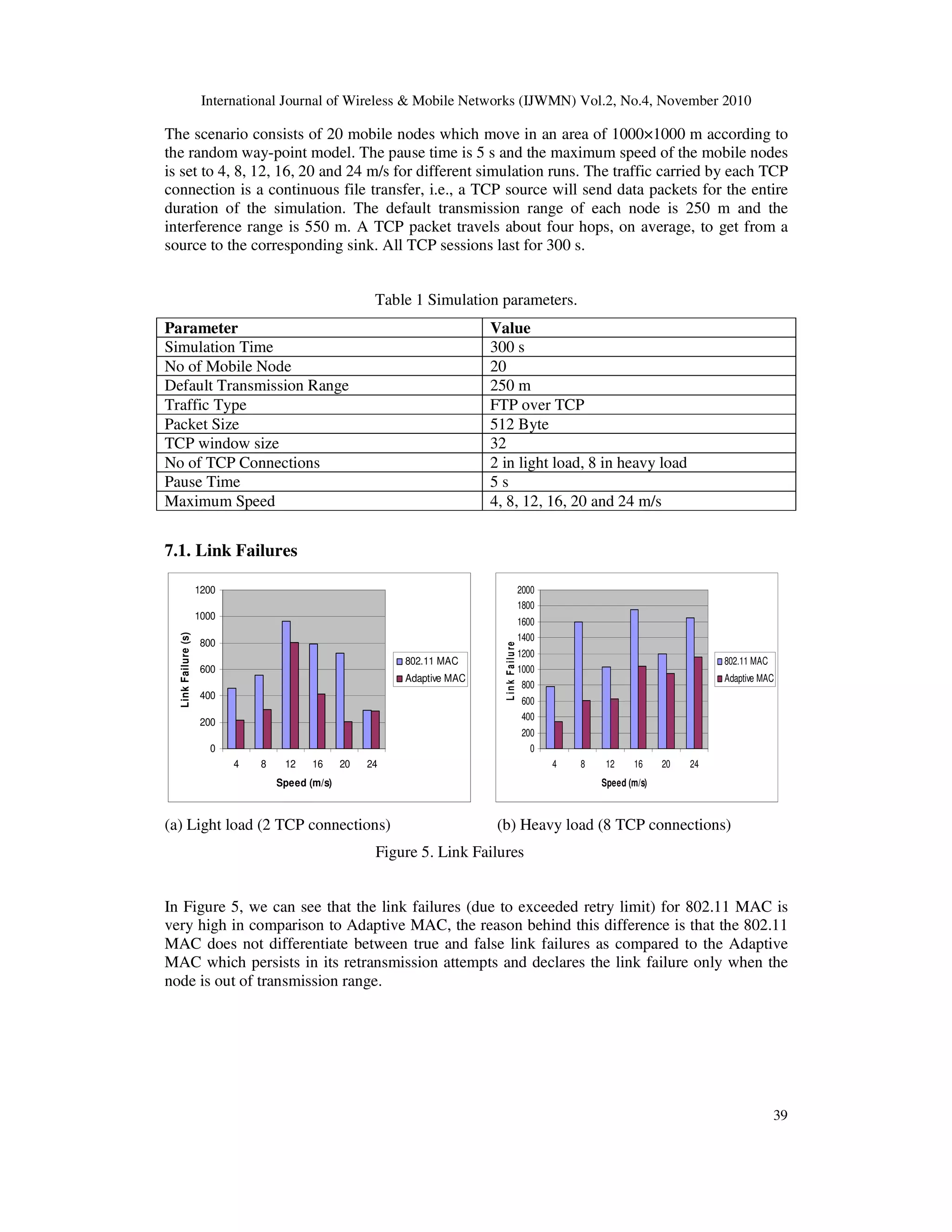
7. SIMULATION AND ANALYSIS
For the purpose of performance analysis of the proposed algorithm, ns-2 [20] simulation tool
has been employed. For our results, we consider two traffic loads, light and heavy. In light
traffic load, there are two TCP connections between two different pairs of nodes. The heavy
traffic load has eight TCP connections (with data flows in different directions) that cross each
other, between eight different pair of nodes. In this simulation, the following performance
metrics have been considered for MANET protocols:
• Link Failures: The total numbers of link failures reported due to exceeded retry limit.
• Normalized Routing Load: The ratio of total routing control packets transmitted and the
total data packets received at the destination.
• Throughput: The rate of successfully received data packets per second in the network.
• Average End to End Delay: The end-to-end-delay is averaged over all received data
packets from the sources to the destinations.](https://image.slidesharecdn.com/1110ijwmn03-220811095448-05c66c12/75/Adapting-Mac-802-11-For-Performance-Optmization-Of-Manet-Using-Cross-Layer-Interaction-8-2048.jpg)
![International Journal of Wireless & Mobile Networks (IJWMN) Vol.2, No.4, November 2010
41
7.4. Average End to End Delay
0
0.1
0.2
0.3
0.4
0.5
0.6
4 8 12 16 20 24
Speed (m/s)
Average
E
nd
to
E
nd
Delay
802.11 MAC
Adaptive MAC
0
0.1
0.2
0.3
0.4
0.5
0.6
4 8 12 16 20 24
Speed (m/s)
A
v
e
ra
g
e
E
n
d
to
E
n
d
D
e
l
a
y
802.11 MAC
Adaptive MAC
(a) Light load (2 TCP connections) (b) Heavy load (8 TCP connections)
Figure 8. Average End to End Delay
As is evident from the results shown in Figure 8, in the case of light load condition, average
end-to-end delay is less in Adaptive MAC as compared to 802.11 MAC, while in the case of
heavy load condition, the delay increases with increased speed of mobile nodes and thus for
delay sensitive application the Adaptive MAC performs well in case of light load scenario.
8. CONCLUSION AND FUTURE WORK
In this paper our objective is to reduce the false link failure in mobile ad hoc networks and
thereby improve their performance. Towards this, we propose an adaptive retransmission limit
algorithm that helps in minimizing false link failures. This algorithm is based on cross layer
interaction which gathers the physical layer statistics and uses, in MAC layer, to determine if a
node is in transmission range or not.
With our extension, the Adaptive MAC dynamically selects the number of retransmission
attempts in order to establish a link. Based on signal strength measurements and time of
overhearing packets, the maximum attempts are performed for strong signal nodes to avoid the
false link failures. Further, our algorithm identifies weak signal nodes, and selects the minimum
number of retransmission attempts which, in turn, helps in switching to the new route even
before the link failure occurs in 802.11 MAC.
The simulation results show that Adaptive MAC can considerably improve the performance of
MANET. It reduces the link failures which cause less route failure and lower routing overhead
in the network. As the routing overhead is decreasing, the nodes are able to transmit more data
packets, consequently, the number of TCP retransmission timeout is reduced and the TCP
source sends more packets, therefore, a higher throughput is obtained.
Future work involves exploiting cross layer interaction in reactive routing protocols such as
DSR or AODV. For example, DSR can use physical layer statistics to determine link quality
and react accordingly.
REFERENCES
[1] Imrich Chlamtac, Marco Conti and Jennifer J.-N. Liu. “Mobile ad hoc networking: imperatives
and challenges,” Ad Hoc Networks, vol. 1, pp. 13–64, 2003.
[2] V. Srivastava and M. Motani. “Cross-layer design: a survey and the road ahead,” IEEE
Communication Magazine, vol. 43, no. 12, pp. 1112–119, 2005.](https://image.slidesharecdn.com/1110ijwmn03-220811095448-05c66c12/75/Adapting-Mac-802-11-For-Performance-Optmization-Of-Manet-Using-Cross-Layer-Interaction-11-2048.jpg)
![International Journal of Wireless & Mobile Networks (IJWMN) Vol.2, No.4, November 2010
42
[3] Fuad Alnajjar, Yahao Chen, “SNR/RP aware routing algorithm: cross-layer design for manets,”
International Journal of Wireless & Mobile Networks (IJWMN), Vol 1, No 2, November 2009.
[4] X. Yin. “Improving tcp performance over mobile ad hoc networks by exploiting cross-layer
information awareness,” in Proc. The 10-th annual international conference on Mobile
computing and networking, Philadelphia, USA, pp. 231–244, 2004.
[5] Kitae Nahm, Ahmed Helmy, and C.-C. Jay Kuo, "Cross-layer Interaction of TCP and Ad Hoc
Routing Protocols in Multihop 802.11 Networks," IEEE Transactions on Mobile Computing
(TMC), vol. 7, no. 4, pp. 458 - 469, 2008.
[6] IEEE Computer Society, “IEEE Standard for Wireless LAN Medium Access Control (MAC)
and Physical Layer (PHY) Specifications”, International Standard ISO/IEC 8802-11: 1999(E),
ANSI/IEEE Std 802.11, 1999 Edition.
[7] J. Li, C. Blake, D. S. J. De Couto, H. Lee, and R. Morris, “Capacity of ad hoc wireless
networks,” in Proc. ACM MobiCom, Rome, Italy, 2001.
[8] K. Xu, M. Gerla, and S. Bae, “How Effective is the IEEE 802.11 RTS/CTS Handshake in Ad
Hoc Networks?” in Proc. GLOBECOM, 2002.
[9] V.Shah, S.V.Krishnamurthy and N.Poojary, “Improving MAC Layer Performance in Ad Hoc
Netowrks of Nodes with Heterogeneous Transmit Power Capabilities,” in Proc. ICC, 2004.
[10] Z. Fu, P. Zerfos, H. Luo, S. Lu, L. Zhang, and M. Gerla, “The impact of multihop wireless
channel on TCP throughput and loss,” in Proc. IEEE INFOCOM, San Francisco, CA, 2003.
[11] Shugong Xu, Tarek Saadawi, “Revealing the problems with 802.11 medium access control
protocol in multi-hop wireless ad hoc networks,” Computer Networks, vol. 38, pp. 531-548,
2002.
[12] C. E. Perkins, E. M. Belding-Royer, S. R. Das, "Ad Hoc On-Demand Distance Vector (AODV)
Routing", IETF MANET Working Group INTERNET DRAFT, 19 January 2002.
[13] D. B. Johnson, D. A. Maltz, Y.-C. Hu, "The Dynamic Source Routing Protocol for Mobile Ad
Hoc Networks (DSR)", IETF MANET Working Group INTERNETDRAFT, 19 July 2004.
[14] Qing Chen Zhisheng Niu, “A delayed adaptive retransmission scheme for false route failure in
MANET”; Proceedings of the 2004 Joint Conference of the 10th Asia-Pacific Conference on
Communications, 2004, Vol. 2, pp. 858 – 862.
[15] Xia Li Kee-Chaing Chua Peng-Yong Kong; “The Study of False Route Breakage in IEEE
802.11 based Ad Hoc Networks”; Proc. of the IEEE International Conference on Mobile Adhoc
and Sensor Systems (MASS), 2006, pp.: 493 – 496.
[16] Hyun Yu Sanghyun Ann “Node Movement Detection to Overcome False Route Failures in
Mobile Ad Hoc Networks”, in International Conference on Information Science and Security,
Seoul 2008.
[17] U. Ashraf, S. Abdellatif and G. Juanole “Efficient Route Maintenance in Wireless Mesh
Networks”, in 3rd International Symposium on Wireless Pervasive Computing (IEEE ISWPC
2008) Santorini, Greece May 2008.
[18] Information Sciences Institute (ISI).The Network Simulator – ns-2. http://www.isi.edu/nsnam/ns/](https://image.slidesharecdn.com/1110ijwmn03-220811095448-05c66c12/75/Adapting-Mac-802-11-For-Performance-Optmization-Of-Manet-Using-Cross-Layer-Interaction-12-2048.jpg)