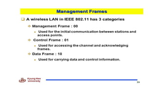
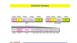
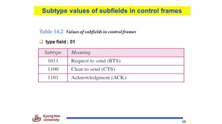
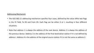
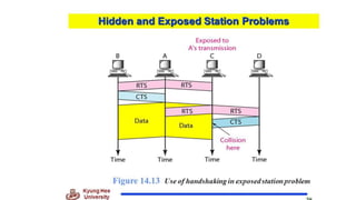
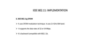
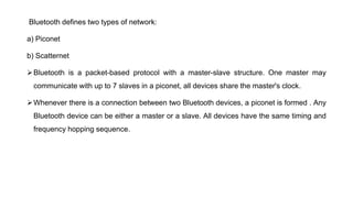
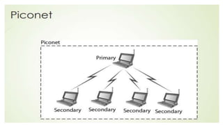
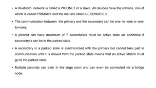
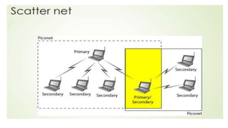
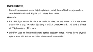
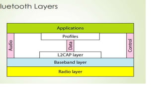
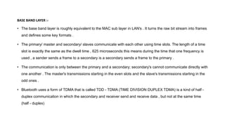
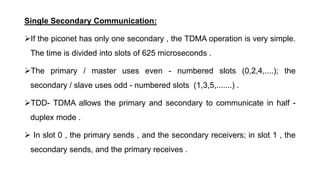
Chapter 14
Wireless LAN
IEEE Standard 802.11
1. Before sending a frame, the source station senses the medium by checking the energy level at the
carrier frequency.
a. The channel uses a persistence strategy with back-off until the channel is idle.
b. After the station is found to be idle, the station waits for a period of time called the distributed
interframe space(DIFS).Then the station sends a control frame called the request to send(RTS).
2. After receiving the RTS and waiting a period of time called the short interframe space (SIFS), the
destination station sends a control frame, called the clear to send (CTS), to the source station. This
control frame indicates that the destination station is ready to receive data.
3. The source station sends data after waiting an amount of time equal to SIFS.
4. The destination station, after waiting an amount of time equal to SIFS, sends an acknowledgment
to show that the frame has been received.
5. Acknowledgment is needed in this protocol because the station does not have any means to
check for the successful arrival of its data at the destination. On the other hand, the lack of
collision in CSMAlCD is a kind of indication to the source that data have arrived.
• Network Allocation Vector How do other stations defer sending their data if one station acquires
access? In other words, how is the collision avoidance aspect of this protocol accomplished? The key is
a feature called NAV.
• When a station sends an RTS frame, it includes the duration oftime that it needs to occupy the
channel. The stations that are affected by this transmission create a timer called a network allocation
vector (NAV) that shows how much time must pass before these stations are allowed to check the
channel for idleness. Each time a station accesses the system and sends an RTS frame, other stations
start their NAV. In other words, each station, before sensing the physical medium to see if it is idle, first
checks its NAV to see if it has expired. Figure 14.5 shows the idea of NAV.
• Collision During Handshaking What happens if there is collision during the time when RTS or CTS
control frames are in transition, often called the handshaking period? Two or more stations may try
to send RTS frames at the same time. These control frames may collide. However, because there is
no mechanism for collision detection, the sender assumes there has been a collision if it has not
received a CTS frame from the receiver. The back-off strategy is employed, and the sender tries
again.
• PCF has a centralized, contention-free polling access method.
• The AP performs polling for stations that are capable of being polled. The stations are polled one after
another, sending any data they have to the AP.
• To give priority to PCF over DCF, another set of interframe spaces has been defined: PIFS and SIFS. The
SIFS is the same as that in DCF, but the PIFS (PCF IFS) is shorter than the DIFS.
• This means that if, at the same time, a station wants to use only DCF and an AP wants to use PCF, the
AP has priority.
• Due to the priority of PCF over DCF, stations that only use DCF may not gain access to the
medium.
• To prevent this, a repetition interval has been designed to cover both contention-free (PCF) and
contention-based (DCF) traffic.
• The repetition interval, which is repeated continuously, starts with a special control frame, called
a beacon frame.
• When the stations hear the beacon frame, they start their NAV for the duration of the contention-
free period of the repetition interval. Figure 14.6 shows an example of a repetition interval.
• During the repetition interval, the PC (point controller) can send a poll frame, receive data, send
an ACK, receive an ACK, or do any combination of these (802.11 uses piggybacking).
• At the end of the contention-free period, the PC sends a CF end (contention-free end) frame to
allow the contention-based stations to use the medium.
D: In all frame types except one, this field defines the duration of the transmission that is
used to set the value of NAY. In one control frame, this field defines the ID of the frame.
Addresses: There are four address fields, each 6 bytes long. The meaning of each address
field depends on the value of the To DS and From DS subfields and will be discussed later.
Sequence control : This field defines the sequence number of the frame to be used in
flow control.
Frame body: This field, which can be between 0 and 2312 bytes, contains information
based on the type and the subtype defined in the FC field.
FCS: The FCS field is 4 bytes long and contains a CRC-32 error detection sequence
Addressing Mechanism
• The IEEE 802.11 addressing mechanism specifies four cases, defined by the value ofthe two flags
in the FC field, To DS and From DS. Each flag can be either 0 or I, resulting in four different
situations.
• Note that address 1 is always the address of the next device. Address 2 is always the address of
the previous device. Address 3 is the address of the final destination station if it is not defined by
address I. Address 4 is the address of the original source station if it is not the same as address 2.
• Figure 14.10 shows an example of the hidden station problem. Station B has a transmission range
shown by the left oval (sphere in space); every station in this range can hear any signal
transmitted by station B.
• Station C has a transmission range shown by the right oval (sphere in space); every station located
in this range can hear any signal transmitted by C.
• Station C is outside the transmission range of B; likewise, station B is outside the transmission
range of C.
• Station A, however, is in the area covered by both Band C; it can hear any signal transmitted by B
or C.
• Assume that station B is sending data to station A.
• In the middle of this transmission, station C also has data to send to station A.
• However, station C is out of B's range and transmissions from B cannot reach C. Therefore C thinks
the medium is free.
• Station C sends its data to A, which results in a collision at A because this station is receiving data
from both B and C.
• In this case, we say that stations Band C are hidden from each other with respect to A.
• Hidden stations can reduce the capacity of the network because of the possibility of collision
• The solution to the hidden station problem is the use of the handshake frames (RTS and CTS) that
we discussed earlier.
• Figure 14.11 shows that the RTS message from B reaches A, but not C. However, because both
Band C are within the range of A, the CTS message, which contains the duration of data
transmission from B to A reaches C.
• Station C knows that some hidden station is using the channel and refrains from transmitting until
that duration is over.
• Now consider a situation that is the inverse of the previous one: the exposed station problem. In
this problem a station refrains from using a channel when it is, in fact, available.
• In Figure 14.12, station A is transmitting to station B.
• Station C has some data to send to station D, which can be sent without interfering with the
transmission from A to B.
• However, station C is exposed to transmission from A; it hears what A is sending and thus refrains
from sending.
• In other words, C is too conservative and wastes the capacity of the channel.
• The handshaking messages RTS and CTS cannot help in this case, despite what you might
think.
• Station C hears the RTS from A, but does not hear the CTS from B. Station C, after
hearing the RTS from A, can wait for a time so that the CTS from B reaches A; it then
sends an RTS to D to show that it needs to communicate with D.
• Both stations B and A may hear this RTS, but station A is in the sending state, not the
receiving state.
• Station B, however, responds with a CTS. The problem is here.
• If station A has started sending its data, station C cannot hear the CTS from station D
because of the collision; it cannot send its data to D.
• It remains exposed until A finishes sending its data as Figure 14.13 shows.
Bluetooth defines two types of network:
a) Piconet
b) Scatternet
Bluetooth is a packet-based protocol with a master-slave structure. One master may
communicate with up to 7 slaves in a piconet, all devices share the master's clock.
Whenever there is a connection between two Bluetooth devices, a piconet is formed . Any
Bluetooth device can be either a master or a slave. All devices have the same timing and
frequency hopping sequence.
• A Bluetooth network is called a PICONET or a slave. All devices have the stations, one of
which is called PRIMARY and the rest are called SECONDRIES .
• The communication between the primary and the secondary can be one- to -one or one-
to-many.
• A piconet can have maximum of 7 secondaries must be active state an additional 8
secondary's can be in the parked state.
• A secondary in a parked state is synchronized with the primary but cannot take part in
communication until it is moved from the parked state means that an active station must
go to the parked state.
• Multiple piconets can exist in the large room and can even be connected via a bridge
node.
• SCATTER NET:-
An interconnected collection of piconets is called a SCATTERNET.
A secondary station in one piconet can be the primary in another piconet. This station can
receive messages from the primary in the piconet and acting as a primary , delivery them
to secondaries in the second piconet.
A station can be a member of two piconets.
Bluetooth Layers
• Bluetooth uses several layers that do not exactly match those of the Internet model we
have defined in this book. Figure 14.21 shows these layers.
RADIO LAYER:-
• The radio layer moves the bits from master to slave , or vice versa . It is a low power
system with a range of meters operating in the 2.4-GHz ISM band . The band is divided
into 79 channels of L MHz each .
• Bluetooth uses the frequency hopping spread spectrum (FHSS) method in the physical
layer to avoid interference from other devices or other networks .
• Bluetooth hops 1600 times per second , which means that each device changes its
modulation frequency 1600 times per second .
• A device uses a frequency for only 625 micro seconds (1/1600 s) before it hops to another
frequency; the dwell times is 625 microseconds .
• To transform bits to a signal , Bluetooth uses a sophisticated version of FSK called GFSK
(FSK with Gaussian bandwidth filtering) . GFSK has a carrier frequency .
BASE BAND LAYER :-
• The base band layer is roughly equivalent to the MAC sub layer in LAN's . It turns the raw bit stream into frames
and defines some key formats .
• The primary/ master and secondary/ slaves communicate with each other using time slots. The length of a time
slot is exactly the same as the dwell time , 625 microseconds this means during the time that one frequency is
used , a sender sends a frame to a secondary is a secondary sends a frame to the primary .
• The communication is only between the primary and a secondary; secondary's cannot communicate directly with
one another . The master's transmissions starting in the even slots and the slave's transmissions starting in the
odd ones .
• Bluetooth uses a form of TDMA that is called TDD - TDMA (TIME DIVISION DUPLEX TDMA) is a kind of half -
duplex communication in which the secondary and receiver send and receive data , but not at the same time
(half - duplex)
Single Secondary Communication:
If the piconet has only one secondary , the TDMA operation is very simple.
The time is divided into slots of 625 microseconds .
The primary / master uses even - numbered slots (0,2,4,....); the
secondary / slave uses odd - numbered slots (1,3,5,.......) .
TDD- TDMA allows the primary and secondary to communicate in half -
duplex mode .
 In slot 0 , the primary sends , and the secondary receivers; in slot 1 , the
secondary sends, and the primary receives .
Multiple Secondary Communication
 The process is a little more involved if there is more than one secondary in the
piconet .
 The primary uses the even - numbered slots but a secondary sends in the next odd
- numbered slot if the packet in the previous slot was addressed to it .
 All secondaries listen on even - numbered slots , but only one secondary sends in
any odd - numbered slot as shown below:
In slot 0 , the primary sends a frame to secondary 1 .
In slot 1 , only secondary 1 sends a frame to the primary because the
previous frame was addressed to secondary 1 ; other secondaries are
silent.
In slot 2 , the primary sends a frame to secondary 2 .
In slot 3 , only secondary 2 send a frame to primary because the previous
frame was addresses to secondary 2 ; other secondaries are silent .
The cycle continues .
This access method is similar to a poll / select operation with reservation . When
the primary selects secondary , it also polls it .
 The next time slot is reserved for the polled station to send its frame , if the
polled secondary has no frame to send , the channel is silent .
Physical Links:
 Each frame is transmitted over a logical channel , called a LINK , between master
and a slave .
Two types of links can be created between a primary and a secondary:
a) Synchronous connection oriented link( SCO )
b) Asynchronous connection link( ACL )
Synchronous Connection Oriented (SCO):
 The other is the SCO link , for real - time data , such as telephone connections .
 SCO link is used when avoiding latency (delay in data delivery) is more important than integrity.
 SCO link , a physical link is created between the primary and a secondary by reserving specific slots at
regular intervals . The basic unit of connection is 2 slots , one for each direction.
Asynchronous Connection Less(ACL):
 It is used when data integrity is more important than avoiding latency.
 In this type of link, if a payload encapsulated in the frame is corrupted, it is retransmitted.
 A secondary returns an ACL frame in the available odd-numbered slot if and only if the previous slot has
been addressed to it.
 ACL can use one, three, or more slots and can achieve a maximum data rate of 721 kbps.
Figure shows the format of the three frame types.
The following describes each field:
 Access code: This 72-bit field normally contains synchronization bits and the identifier of the
primary to distinguish the frame of one piconet from another.
 Header. This 54-bit field is a repeated I8-bit pattern. Each pattern has the following subfields:
1. Address: The 3-bit address subfield can define up to seven secondaries (l to 7)If the address is
zero, it is used for broadcast communication from the primary to all secondaries.
2. Type: The 4-bit type subfield defines the type of data coming from the upper layers. We discuss
these types later.
3. F:This I-bit subfield is for flow control. When set (I), it indicates that the device is unable to
receive more frames (buffer is full).
4. A: This I-bit subfield is for acknowledgment. Bluetooth uses Stop-and-Wait ARQ; I bit is sufficient
for acknowledgment.
5. S: This I-bit subfield holds a sequence number. Bluetooth uses Stop-and-Wait ARQ; I bit is
sufficient for sequence numbering.
6. HEC: The 8-bit header error correction subfield is a checksum to detect errors in each 18-bit
header section.
The header has three identical 18-bit sections. The receiver compares these three sections,
bit by bit. If each of the corresponding bits is the same, the bit is accepted; if not, the
majority opinion rules.
This is a form of forward error correction (for the header only). This double error control is
needed because the nature of the communication, via air, is very noisy. Note that there is no
retransmission in this sublayer.
Payload. This subfield can be 0 to 2740 bits long. It contains data or control information
coming from the upper layers.
L2CAP :
 The logical link control and adaptation protocol or L2CAP is equivalent to the LLC sub layer
in LAN's .
 It is used for data exchange on an ACL link . SCO channel do not use L2CAP .The below fig :
shows the format of the data packet at this level .
1. The length field in the data packet represents the size of the data , coming from the
upper layers . This length field is 2 - bytes .
2. The maximum data , it can support is 65,535 bytes .
3. The unique identifier for the virtual channel created at this level is defined by
channel ID.
The L2CAP ha specific duties :
a) Multiplexing
b) Segmentation and Reassembly
c) Quality of service , and
d) group management .
 MULTIPLEXING:
This layer handles multiplexing and de-multiplexing of packets from different upper
layer sources . The L2CAP can multiplexing .
 At the sender site , it accepts data from one of the upper - layer protocols , frames
them , and delivers them to the base band layer .
 At the receiver site , it accepts a frame from the base band layer , extracts the data ,
and delivers them to the appropriate protocol layer .
SEGMENTATION AND REASSEMBLY:
 The maximum size of the payload field in the base band layer is 2774 bits , or 343 bytes .
 This includes 4 bytes to define the packet and packet length , so the size of the packet that
can arrive from an upper layer can only be 339 bytes .
 The L2CAP divides these large packets into smaller segments and adds extra information
to define the location of the segments in the original packet .
 The L2CAP segments the packet at the source and reassembles them at the destination .
GROUP MANAGEMENT:-
Another functionality of L2CAP is to allow devices to create a type of logical addressing between
themselves . This is similar to multi casting .
QUALITY OF SERVICE:-
This layer is responsible for quality of service when the link is in establishing state or when the
link is in normal state of operation .
Wireless lan IEEE standard 802.11 chapter

Wireless lan IEEE standard 802.11 chapter

  • 1.
  • 10.
    1. Before sendinga frame, the source station senses the medium by checking the energy level at the carrier frequency. a. The channel uses a persistence strategy with back-off until the channel is idle. b. After the station is found to be idle, the station waits for a period of time called the distributed interframe space(DIFS).Then the station sends a control frame called the request to send(RTS). 2. After receiving the RTS and waiting a period of time called the short interframe space (SIFS), the destination station sends a control frame, called the clear to send (CTS), to the source station. This control frame indicates that the destination station is ready to receive data.
  • 11.
    3. The sourcestation sends data after waiting an amount of time equal to SIFS. 4. The destination station, after waiting an amount of time equal to SIFS, sends an acknowledgment to show that the frame has been received. 5. Acknowledgment is needed in this protocol because the station does not have any means to check for the successful arrival of its data at the destination. On the other hand, the lack of collision in CSMAlCD is a kind of indication to the source that data have arrived.
  • 12.
    • Network AllocationVector How do other stations defer sending their data if one station acquires access? In other words, how is the collision avoidance aspect of this protocol accomplished? The key is a feature called NAV. • When a station sends an RTS frame, it includes the duration oftime that it needs to occupy the channel. The stations that are affected by this transmission create a timer called a network allocation vector (NAV) that shows how much time must pass before these stations are allowed to check the channel for idleness. Each time a station accesses the system and sends an RTS frame, other stations start their NAV. In other words, each station, before sensing the physical medium to see if it is idle, first checks its NAV to see if it has expired. Figure 14.5 shows the idea of NAV.
  • 13.
    • Collision DuringHandshaking What happens if there is collision during the time when RTS or CTS control frames are in transition, often called the handshaking period? Two or more stations may try to send RTS frames at the same time. These control frames may collide. However, because there is no mechanism for collision detection, the sender assumes there has been a collision if it has not received a CTS frame from the receiver. The back-off strategy is employed, and the sender tries again.
  • 15.
    • PCF hasa centralized, contention-free polling access method. • The AP performs polling for stations that are capable of being polled. The stations are polled one after another, sending any data they have to the AP. • To give priority to PCF over DCF, another set of interframe spaces has been defined: PIFS and SIFS. The SIFS is the same as that in DCF, but the PIFS (PCF IFS) is shorter than the DIFS. • This means that if, at the same time, a station wants to use only DCF and an AP wants to use PCF, the AP has priority.
  • 16.
    • Due tothe priority of PCF over DCF, stations that only use DCF may not gain access to the medium. • To prevent this, a repetition interval has been designed to cover both contention-free (PCF) and contention-based (DCF) traffic. • The repetition interval, which is repeated continuously, starts with a special control frame, called a beacon frame. • When the stations hear the beacon frame, they start their NAV for the duration of the contention- free period of the repetition interval. Figure 14.6 shows an example of a repetition interval. • During the repetition interval, the PC (point controller) can send a poll frame, receive data, send an ACK, receive an ACK, or do any combination of these (802.11 uses piggybacking). • At the end of the contention-free period, the PC sends a CF end (contention-free end) frame to allow the contention-based stations to use the medium.
  • 19.
    D: In allframe types except one, this field defines the duration of the transmission that is used to set the value of NAY. In one control frame, this field defines the ID of the frame. Addresses: There are four address fields, each 6 bytes long. The meaning of each address field depends on the value of the To DS and From DS subfields and will be discussed later. Sequence control : This field defines the sequence number of the frame to be used in flow control. Frame body: This field, which can be between 0 and 2312 bytes, contains information based on the type and the subtype defined in the FC field. FCS: The FCS field is 4 bytes long and contains a CRC-32 error detection sequence
  • 23.
    Addressing Mechanism • TheIEEE 802.11 addressing mechanism specifies four cases, defined by the value ofthe two flags in the FC field, To DS and From DS. Each flag can be either 0 or I, resulting in four different situations. • Note that address 1 is always the address of the next device. Address 2 is always the address of the previous device. Address 3 is the address of the final destination station if it is not defined by address I. Address 4 is the address of the original source station if it is not the same as address 2.
  • 30.
    • Figure 14.10shows an example of the hidden station problem. Station B has a transmission range shown by the left oval (sphere in space); every station in this range can hear any signal transmitted by station B. • Station C has a transmission range shown by the right oval (sphere in space); every station located in this range can hear any signal transmitted by C. • Station C is outside the transmission range of B; likewise, station B is outside the transmission range of C. • Station A, however, is in the area covered by both Band C; it can hear any signal transmitted by B or C.
  • 31.
    • Assume thatstation B is sending data to station A. • In the middle of this transmission, station C also has data to send to station A. • However, station C is out of B's range and transmissions from B cannot reach C. Therefore C thinks the medium is free. • Station C sends its data to A, which results in a collision at A because this station is receiving data from both B and C. • In this case, we say that stations Band C are hidden from each other with respect to A. • Hidden stations can reduce the capacity of the network because of the possibility of collision
  • 33.
    • The solutionto the hidden station problem is the use of the handshake frames (RTS and CTS) that we discussed earlier. • Figure 14.11 shows that the RTS message from B reaches A, but not C. However, because both Band C are within the range of A, the CTS message, which contains the duration of data transmission from B to A reaches C. • Station C knows that some hidden station is using the channel and refrains from transmitting until that duration is over.
  • 36.
    • Now considera situation that is the inverse of the previous one: the exposed station problem. In this problem a station refrains from using a channel when it is, in fact, available. • In Figure 14.12, station A is transmitting to station B. • Station C has some data to send to station D, which can be sent without interfering with the transmission from A to B. • However, station C is exposed to transmission from A; it hears what A is sending and thus refrains from sending. • In other words, C is too conservative and wastes the capacity of the channel.
  • 37.
    • The handshakingmessages RTS and CTS cannot help in this case, despite what you might think. • Station C hears the RTS from A, but does not hear the CTS from B. Station C, after hearing the RTS from A, can wait for a time so that the CTS from B reaches A; it then sends an RTS to D to show that it needs to communicate with D. • Both stations B and A may hear this RTS, but station A is in the sending state, not the receiving state. • Station B, however, responds with a CTS. The problem is here. • If station A has started sending its data, station C cannot hear the CTS from station D because of the collision; it cannot send its data to D. • It remains exposed until A finishes sending its data as Figure 14.13 shows.
  • 52.
    Bluetooth defines twotypes of network: a) Piconet b) Scatternet Bluetooth is a packet-based protocol with a master-slave structure. One master may communicate with up to 7 slaves in a piconet, all devices share the master's clock. Whenever there is a connection between two Bluetooth devices, a piconet is formed . Any Bluetooth device can be either a master or a slave. All devices have the same timing and frequency hopping sequence.
  • 54.
    • A Bluetoothnetwork is called a PICONET or a slave. All devices have the stations, one of which is called PRIMARY and the rest are called SECONDRIES . • The communication between the primary and the secondary can be one- to -one or one- to-many. • A piconet can have maximum of 7 secondaries must be active state an additional 8 secondary's can be in the parked state. • A secondary in a parked state is synchronized with the primary but cannot take part in communication until it is moved from the parked state means that an active station must go to the parked state. • Multiple piconets can exist in the large room and can even be connected via a bridge node.
  • 55.
    • SCATTER NET:- Aninterconnected collection of piconets is called a SCATTERNET. A secondary station in one piconet can be the primary in another piconet. This station can receive messages from the primary in the piconet and acting as a primary , delivery them to secondaries in the second piconet. A station can be a member of two piconets.
  • 57.
    Bluetooth Layers • Bluetoothuses several layers that do not exactly match those of the Internet model we have defined in this book. Figure 14.21 shows these layers. RADIO LAYER:- • The radio layer moves the bits from master to slave , or vice versa . It is a low power system with a range of meters operating in the 2.4-GHz ISM band . The band is divided into 79 channels of L MHz each . • Bluetooth uses the frequency hopping spread spectrum (FHSS) method in the physical layer to avoid interference from other devices or other networks .
  • 58.
    • Bluetooth hops1600 times per second , which means that each device changes its modulation frequency 1600 times per second . • A device uses a frequency for only 625 micro seconds (1/1600 s) before it hops to another frequency; the dwell times is 625 microseconds . • To transform bits to a signal , Bluetooth uses a sophisticated version of FSK called GFSK (FSK with Gaussian bandwidth filtering) . GFSK has a carrier frequency .
  • 60.
    BASE BAND LAYER:- • The base band layer is roughly equivalent to the MAC sub layer in LAN's . It turns the raw bit stream into frames and defines some key formats . • The primary/ master and secondary/ slaves communicate with each other using time slots. The length of a time slot is exactly the same as the dwell time , 625 microseconds this means during the time that one frequency is used , a sender sends a frame to a secondary is a secondary sends a frame to the primary . • The communication is only between the primary and a secondary; secondary's cannot communicate directly with one another . The master's transmissions starting in the even slots and the slave's transmissions starting in the odd ones . • Bluetooth uses a form of TDMA that is called TDD - TDMA (TIME DIVISION DUPLEX TDMA) is a kind of half - duplex communication in which the secondary and receiver send and receive data , but not at the same time (half - duplex)
  • 61.
    Single Secondary Communication: Ifthe piconet has only one secondary , the TDMA operation is very simple. The time is divided into slots of 625 microseconds . The primary / master uses even - numbered slots (0,2,4,....); the secondary / slave uses odd - numbered slots (1,3,5,.......) . TDD- TDMA allows the primary and secondary to communicate in half - duplex mode .  In slot 0 , the primary sends , and the secondary receivers; in slot 1 , the secondary sends, and the primary receives .
  • 63.
    Multiple Secondary Communication The process is a little more involved if there is more than one secondary in the piconet .  The primary uses the even - numbered slots but a secondary sends in the next odd - numbered slot if the packet in the previous slot was addressed to it .  All secondaries listen on even - numbered slots , but only one secondary sends in any odd - numbered slot as shown below:
  • 65.
    In slot 0, the primary sends a frame to secondary 1 . In slot 1 , only secondary 1 sends a frame to the primary because the previous frame was addressed to secondary 1 ; other secondaries are silent. In slot 2 , the primary sends a frame to secondary 2 . In slot 3 , only secondary 2 send a frame to primary because the previous frame was addresses to secondary 2 ; other secondaries are silent . The cycle continues .
  • 66.
    This access methodis similar to a poll / select operation with reservation . When the primary selects secondary , it also polls it .  The next time slot is reserved for the polled station to send its frame , if the polled secondary has no frame to send , the channel is silent .
  • 67.
    Physical Links:  Eachframe is transmitted over a logical channel , called a LINK , between master and a slave . Two types of links can be created between a primary and a secondary: a) Synchronous connection oriented link( SCO ) b) Asynchronous connection link( ACL )
  • 68.
    Synchronous Connection Oriented(SCO):  The other is the SCO link , for real - time data , such as telephone connections .  SCO link is used when avoiding latency (delay in data delivery) is more important than integrity.  SCO link , a physical link is created between the primary and a secondary by reserving specific slots at regular intervals . The basic unit of connection is 2 slots , one for each direction. Asynchronous Connection Less(ACL):  It is used when data integrity is more important than avoiding latency.  In this type of link, if a payload encapsulated in the frame is corrupted, it is retransmitted.  A secondary returns an ACL frame in the available odd-numbered slot if and only if the previous slot has been addressed to it.  ACL can use one, three, or more slots and can achieve a maximum data rate of 721 kbps.
  • 70.
    Figure shows theformat of the three frame types. The following describes each field:  Access code: This 72-bit field normally contains synchronization bits and the identifier of the primary to distinguish the frame of one piconet from another.  Header. This 54-bit field is a repeated I8-bit pattern. Each pattern has the following subfields: 1. Address: The 3-bit address subfield can define up to seven secondaries (l to 7)If the address is zero, it is used for broadcast communication from the primary to all secondaries. 2. Type: The 4-bit type subfield defines the type of data coming from the upper layers. We discuss these types later. 3. F:This I-bit subfield is for flow control. When set (I), it indicates that the device is unable to receive more frames (buffer is full). 4. A: This I-bit subfield is for acknowledgment. Bluetooth uses Stop-and-Wait ARQ; I bit is sufficient for acknowledgment. 5. S: This I-bit subfield holds a sequence number. Bluetooth uses Stop-and-Wait ARQ; I bit is sufficient for sequence numbering. 6. HEC: The 8-bit header error correction subfield is a checksum to detect errors in each 18-bit header section.
  • 71.
    The header hasthree identical 18-bit sections. The receiver compares these three sections, bit by bit. If each of the corresponding bits is the same, the bit is accepted; if not, the majority opinion rules. This is a form of forward error correction (for the header only). This double error control is needed because the nature of the communication, via air, is very noisy. Note that there is no retransmission in this sublayer. Payload. This subfield can be 0 to 2740 bits long. It contains data or control information coming from the upper layers.
  • 72.
    L2CAP :  Thelogical link control and adaptation protocol or L2CAP is equivalent to the LLC sub layer in LAN's .  It is used for data exchange on an ACL link . SCO channel do not use L2CAP .The below fig : shows the format of the data packet at this level .
  • 73.
    1. The lengthfield in the data packet represents the size of the data , coming from the upper layers . This length field is 2 - bytes . 2. The maximum data , it can support is 65,535 bytes . 3. The unique identifier for the virtual channel created at this level is defined by channel ID. The L2CAP ha specific duties : a) Multiplexing b) Segmentation and Reassembly c) Quality of service , and d) group management .
  • 74.
     MULTIPLEXING: This layerhandles multiplexing and de-multiplexing of packets from different upper layer sources . The L2CAP can multiplexing .  At the sender site , it accepts data from one of the upper - layer protocols , frames them , and delivers them to the base band layer .  At the receiver site , it accepts a frame from the base band layer , extracts the data , and delivers them to the appropriate protocol layer .
  • 75.
    SEGMENTATION AND REASSEMBLY: The maximum size of the payload field in the base band layer is 2774 bits , or 343 bytes .  This includes 4 bytes to define the packet and packet length , so the size of the packet that can arrive from an upper layer can only be 339 bytes .  The L2CAP divides these large packets into smaller segments and adds extra information to define the location of the segments in the original packet .  The L2CAP segments the packet at the source and reassembles them at the destination .
  • 76.
    GROUP MANAGEMENT:- Another functionalityof L2CAP is to allow devices to create a type of logical addressing between themselves . This is similar to multi casting . QUALITY OF SERVICE:- This layer is responsible for quality of service when the link is in establishing state or when the link is in normal state of operation .